Page 2092 of 4171

EXL-144
< ON-VEHICLE REPAIR >
ADJUSTMENT AND INSPECTION
NOTE:
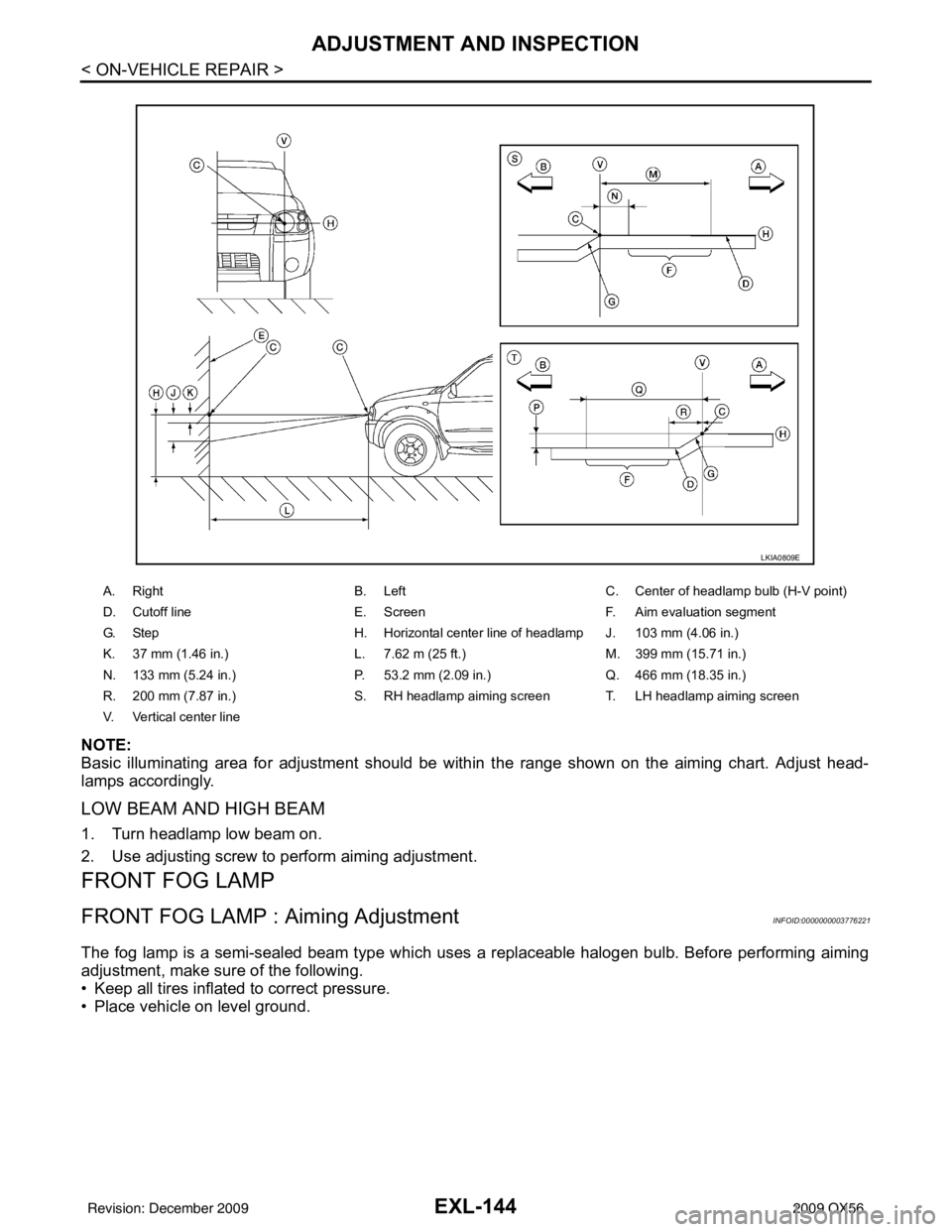
Basic illuminating area for adjustment should be within the range shown on the aiming chart. Adjust head-
lamps accordingly.
LOW BEAM AND HIGH BEAM
1. Turn headlamp low beam on.
2. Use adjusting screw to perform aiming adjustment.
FRONT FOG LAMP
FRONT FOG LAMP : Aiming AdjustmentINFOID:0000000003776221
The fog lamp is a semi-sealed beam type which uses a replaceable halogen bulb. Before performing aiming
adjustment, make sure of the following.
• Keep all tires inflated to correct pressure.
• Place vehicle on level ground.
A. RightB. Left C. Center of headlamp bulb (H-V point)
D. Cutoff line E. ScreenF. Aim evaluation segment
G. Step H. Horizontal center line of headlamp J. 103 mm (4.06 in.)
K. 37 mm (1.46 in.) L. 7.62 m (25 ft.) M. 399 mm (15.71 in.)
N. 133 mm (5.24 in.) P. 53.2 mm (2.09 in.)Q. 466 mm (18.35 in.)
R. 200 mm (7.87 in.) S. RH headlamp aiming screen T. LH headlamp aiming screen
V. Vertical center line
LKIA0809E
Revision: December 20092009 QX56
Page 2094 of 4171

EXL-146
< REMOVAL AND INSTALLATION >
HEADLAMP
REMOVAL AND INSTALLATION
HEADLAMP
Bulb ReplacementINFOID:0000000003776222
CAUTION:
• Disconnect battery negative terminal before touching xenon bulb or headlamp wiring harness
assembly.
• Turn headlamp switch OFF before disconnecting headlamp harness connector.
• Do not touch bulb by hand right after being turned off. Burning may result.
• Do not touch the glass of bulb directly by hand. Keep grease and other oily substances away from it.
• Do not turn xenon bulb ON wh en xenon bulb is removed from front combination lamp assembly.
• After installing the bulb, be sure to install the bulb socket securely to ensure watertightness.
• Do not leave bulb out of front combination lamp assembly for a long time because dust, moisture,
smoke, etc. may affect the performa nce of the lamp. When replacing bulb, be sure to replace it with a
new one.
HEADLAMP (OUTER SIDE), FOR LOW BEAM
Removal
1. Position fender protector aside.
2. Turn headlamp switch OFF.
3. Disconnect battery negative terminal.
4. Remove ballast.
5. Disconnect headlamp electrical connector.
6. Release bulb retaining spring and pull bulb straight out.
Installation
Installation is in the reverse order of removal.
HEADLAMP (INNER SIDE), FOR HIGH BEAM
Removal
1. Turn headlamp switch OFF.
2. Disconnect headlamp electrical connector.
3. Turn the bulb counterclockwise to remove it.
Installation
Installation is in the reverse order of removal.
FRONT PARKING LAMP (INNER OR OUTER)
Removal
1. Turn the bulb socket counterclockwise to unlock it.
2. Pull the bulb to remove it from the socket.
Installation
Installation is in the reverse order of removal.
SIDE MARKER LAMP (FRONT)
Removal
1. Position fender protector aside.
2. Turn the side marker lamp (front) bulb socket counterclockwise and remove side marker lamp (front) bulb socket.
3. Pull to remove side marker lamp (front) fr om the side marker lamp (front) bulb socket.
Installation
Installation is in the reverse order of removal.
Revision: December 20092009 QX56
Page 2095 of 4171

HEADLAMPEXL-147
< REMOVAL AND INSTALLATION >
C
DE
F
G H
I
J
K
M A
B
EXL
N
O P
Removal and InstallationINFOID:0000000003776223
FRONT COMBINATION LAMP ASSEMBLY
CAUTION:
• Disconnect battery negative terminal before touc hing xenon bulb or headlamp wiring harness
assembly.
• Turn headlamp switch OFF before di sconnecting headlamp harness connector.
• Do not touch bulb by hand right after being turned off. Burning may result.
• Do not touch the glass of bulb directly by hand. Keep grease and other oily substances away from it.
• Do not turn xenon bulb ON when xenon bulb is removed fr om front combination lamp assembly.
• After installing the bu lb, be sure to install the bulb socket securely to ensure watertightness.
• Do not leave bulb out of front combination lamp assembly for a lo ng time because dust, moisture,
smoke, etc. may affect the performance of the lamp. When replacing bulb, be sure to replace it with a
new one.
Removal
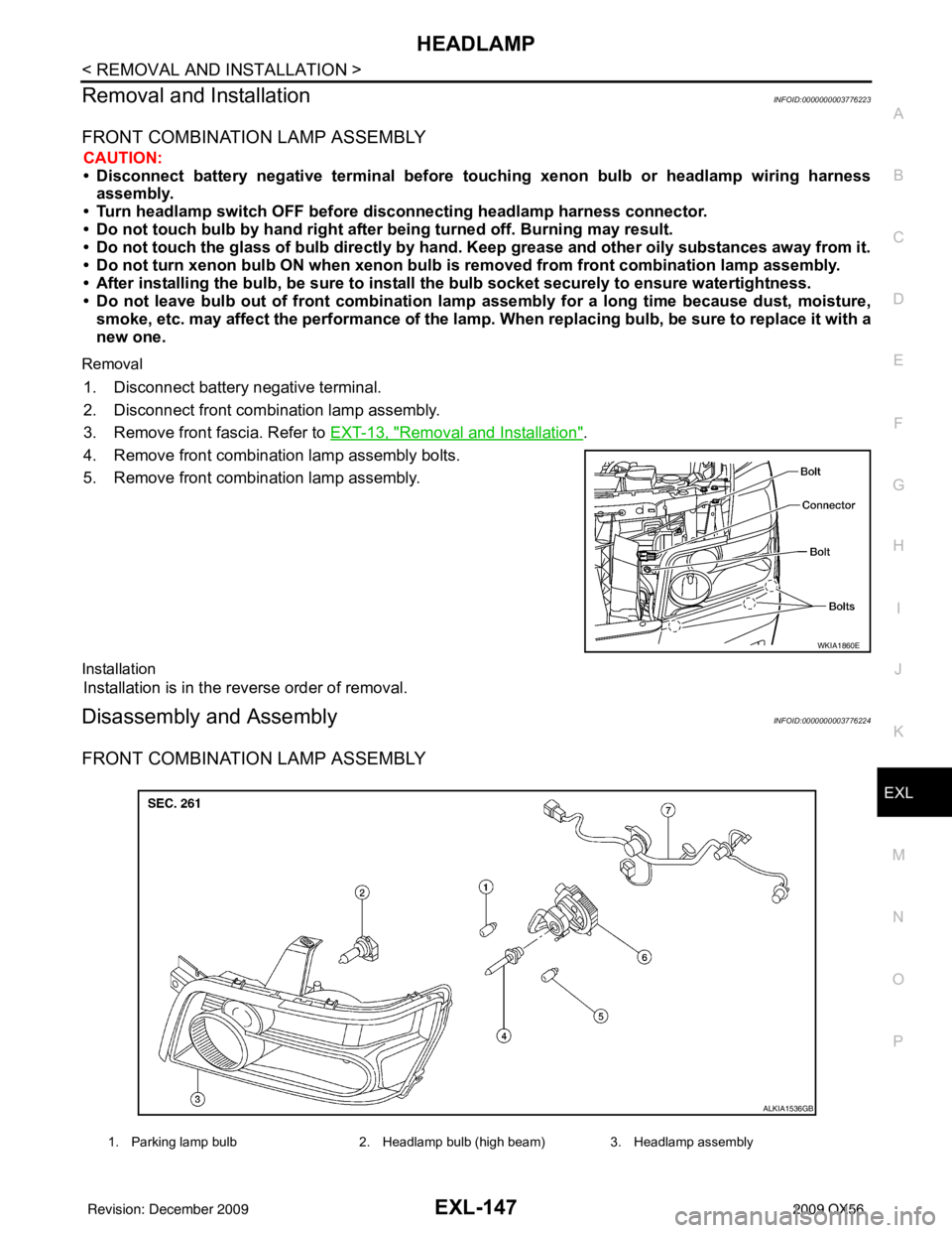
1. Disconnect battery negative terminal.
2. Disconnect front combination lamp assembly.
3. Remove front fascia. Refer to EXT-13, "
Removal and Installation".
4. Remove front combination lamp assembly bolts.
5. Remove front combination lamp assembly.
Installation
Installation is in the reverse order of removal.
Disassembly and AssemblyINFOID:0000000003776224
FRONT COMBINATION LAMP ASSEMBLY
WKIA1860E
1. Parking lamp bulb 2. Headlamp bulb (high beam) 3. Headlamp assembly
ALKIA1536GB
Revision: December 20092009 QX56
Page 2096 of 4171
EXL-148
< REMOVAL AND INSTALLATION >
HEADLAMP
Disassembly
1. Remove ballast.
2. Release xenon bulb retaining spring and remove xenon bulb.
3. Turn high beam bulb counterclockwise to unlock and remove high beam bulb.
4. Turn parking lamp bulb socket counterclockwise to unlock and remove parking lamp bulb.
5. Turn side marker lamp (front) bulb socket counterclockwise to unlock and remove side marker lamp (front)
bulb.
Assembly
Assembly is in the reverse order of disassembly.
4. Xenon bulb (low beam) 5. Side marker lamp (front) bulb 6. Ballast
7. Wiring harness assembly
Revision: December 20092009 QX56
Page 2098 of 4171

EXL-150
< REMOVAL AND INSTALLATION >
FRONT FOG LAMP
FRONT FOG LAMP
Bulb ReplacementINFOID:0000000003776226
FRONT FOG LAMP
Removal
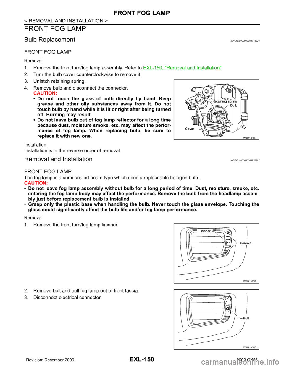
1. Remove the front turn/fog lamp assembly. Refer to EXL-150, "Removal and Installation".
2. Turn the bulb cover counterclockwise to remove it.
3. Unlatch retaining spring.
4. Remove bulb and disconnect the connector. CAUTION:
• Do not touch the glass of bulb directly by hand. Keep
grease and other oily substances away from it. Do not
touch bulb by hand while it is lit or right after being turned
off. Burning may result.
• Do not leave bulb out of fog la mp reflector for a long time
because dust, moisture smoke, etc. may affect the perfor-
mance of fog lamp. When replacing bulb, be sure to
replace it with new one.
Installation
Installation is in the reverse order of removal.
Removal and InstallationINFOID:0000000003776227
FRONT FOG LAMP
The fog lamp is a semi-sealed beam type which uses a replaceable halogen bulb.
CAUTION:
• Do not leave fog lamp assembly without bulb for a long period of time. Dust, moisture, smoke, etc. entering the fog lamp body may affect the perf ormance. Remove the bulb from the headlamp assem-
bly just before replacement bulb is installed.
• Grasp only the plastic base when handling the bulb. Never touch the glass envelope. Touching the
glass could significantly affect the bulb life and/or fog lamp performance.
Removal
1. Remove the front turn/fog lamp finisher.
2. Remove bolt and pull fog lamp out of front fascia.
3. Disconnect electrical connector.
WKIA1886E
WKIA1887E
WKIA1888E
Revision: December 20092009 QX56
Page 2106 of 4171
EXL-158
< SERVICE DATA AND SPECIFICATIONS (SDS)
BULB SPECIFICATIONS
SERVICE DATA AND SPECIFICATIONS (SDS)
BULB SPECIFICATIONS
HeadlampINFOID:0000000003776236
*: Always check with the Parts Department for the latest parts information.
Exterior LampINFOID:0000000003776237
*: Always check with the Parts Department for the latest parts information.Item
Wattage (W)*
Low 35
High 60/65
ItemWattage (W)*
Front combination lamp Parking lamp (inner)
7
Parking lamp (outer) 7
Side marker lamp (front) 7
Rear combination lamp Stop/Tail lamp
LED*
Side marker lamp (rear) *
Turn signal lamp 27
Back-up lamp *
Turn/fog lamp Fog
55
Turn 21
License plate lamp *
High-mounted stop lamp LED*
Revision: December 20092009 QX56
Page 2120 of 4171

EXT-14
< SERVICE INFORMATION >
FRONT BUMPER
REMOVAL
1. Remove the side screws from the front fascia assembly.
2. Remove the screws from the front of fender protector. Refer to EXT-23
.
3. Remove the fog turn/fog lamp finisher and the fog turn/fog lamp. • Disconnect the harnesses.
4. Disconnect the sonar sensor, if equipped harness connector under the front fascia assembly.
5. Remove the fasteners, release the clips and remove the front fascia assembly.
6. Remove the plastic clips and remove the upper energy absorber.
7. Remove the upper bumper reinforcement.
8. Remove the plastic clips and remove the lower energy absorber.
9. Remove the front bumper stays and the front bumper side brackets, LH and RH.
10. Disconnect the sonar sensors, if equipped from the sonar sensor retainers, if equipped.
11. Remove the sonar sensors, if equipped and harness from the front fascia assembly. • Disconnect the sonar sensors, if equipped from the harness.
• Remove the sonar sensor retainers, if equipped from the front fascia assembly.
INSTALLATION
Installation is in the reverse order of removal.
7. Sonar sensor harness (if equipped) 8. Front fascia assembly 9. Sonar sensor retainers (if equipped)
10. Engine under cover 11. Front fascia bracket12. License plate bracket
13. Fog turn/fog lamp finisher LH/RH 14. Fog turn/fog lamp 15. Front bumper stay LH
16. Front bumper side bracket LH 17. Headlamp finisher (RH shown) A. Clip C103
B. Clip CS101
Revision: December 20092009 QX56
Page 2126 of 4171
EXT-20
< SERVICE INFORMATION >
FRONT FENDER
FRONT FENDER
Removal and InstallationINFOID:0000000003776108
REMOVAL
1. Remove the headlamp assembly. Refer to EXL-147, "Removal and Installation".
2. Remove the over fender. Refer to EXT-21
.
3. Remove the fender protector. Refer to EXT-23
.
4. Remove the hood stay. Refer to DLK-230, "
Removal and Installation of Hood Assembly".
5. Remove the front fender.
INSTALLATION
Installation is in the reverse order of removal.
1. Front fender 2. Over fender3. Headlamp assembly
4. Fender protector
WIIA0956E
Revision: December 20092009 QX56