Page 3500 of 4171

SRC-2
Diagnosis Procedure (Component Diagnosis) ........39
B1086 – B1089 SEAT BELT PRE-TENSION-
ER LH .................................................................
41
Description ........................................................... ...41
DTC Logic ...............................................................41
Diagnosis Procedure (Component Diagnosis) ........42
B1081 – B1084 SEAT BELT PRE-TENSION-
ER RH ................................................................
44
Description ..............................................................44
DTC Logic ...............................................................44
Diagnosis Procedure (Component Diagnosis) ........45
B1182 - B1185 SEAT BELT BUCKLE PRE-
TENSIONER LH .................................................
47
Description ........................................................... ...47
DTC Logic ...............................................................47
Diagnosis Procedure (Component Diagnosis) ........48
B1177 - B1180 SEAT BELT BUCKLE PRE-
TENSIONER RH ................................................
50
Description ........................................................... ...50
DTC Logic ...............................................................50
Diagnosis Procedure (Component Diagnosis) ........51
B1033 – B1035 CRASH ZONE SENSOR .........53
Description ........................................................... ...53
DTC Logic ...............................................................53
Diagnosis Procedure (Component Diagnosis) ........54
B1118 – B1120 SATELLITE SENSOR LH ........56
Description ........................................................... ...56
DTC Logic ...............................................................56
Diagnosis Procedure (Component Diagnosis) ........57
B1113 – B1115 SATELLITE SENSOR RH .......59
Description ........................................................... ...59
DTC Logic ...............................................................59
Diagnosis Procedure (Component Diagnosis) ........60
B1XXX AIR BAG DIAGNOSIS SENSOR UNIT ...62
Description ........................................................... ...62
DTC Logic ...............................................................62
Diagnosis Procedure (Component Diagnosis) ........63
B1023 PASSENGER AIR BAG OFF INDICA-
TOR ....................................................................
64
Description ........................................................... ...64
DTC Logic ...............................................................64
Diagnosis Procedure (Component Diagnosis) ........65
B1017 – B1022 OCCUPANT CLASSIFICA-
TION SYSTEM ................................................ ...
67
Description ........................................................... ...67
DTC Logic ...............................................................67
Diagnosis Procedure (Component Diagnosis) ........68
B1209 – B1211 COLLISION DETECTION ........71
Description ........................................................... ...71
DTC Logic ...............................................................71
Diagnosis Procedure (Component Diagnosis) ........71
ECU DIAGNOSIS .......................................72
DIAGNOSIS SENSOR UNIT .............................72
Wiring Diagram .................................................... ...72
Trouble Diagnosis with CONSULT-III .....................81
Trouble Diagnosis without CONSULT-III ................85
SYMPTOM DIAGNOSIS ............................90
SRS AIR BAG SYSTEM ................................. ...90
"AIR BAG" Warning Lamp Does Not Turn Off ..... ...90
"AIR BAG" Warning Lamp Does Not Turn On ........90
PASSENGER SEAT BELT WARNING SYS-
TEM ....................................................................
92
Seat Belt Warning System Does Not Function .... ...92
PRECAUTION ............................................93
PRECAUTIONS .............................................. ...93
Precaution for Supplemental Restraint System
(SRS) "AIR BAG" and "SEAT BELT PRE-TEN-
SIONER" .............................................................. ...
93
Precaution for SRS "AIR BAG" and "SEAT BELT
PRE-TENSIONER" Service ................................. ...
93
Occupant Classification System Precaution ...........93
Revision: December 20092009 QX56
Page 3501 of 4171
DIAGNOSIS AND REPAIR WORK FLOWSRC-3
< BASIC INSPECTION >
C
DE
F
G
I
J
K L
M A
B
SRC
N
O P
BASIC INSPECTION
DIAGNOSIS AND REPAIR WORK FLOW
Work FlowINFOID:0000000003775168
OVERALL SEQUENCE
DETAILED WORK FLOW
1.CUSTOMER INFORMATION
Get detailed information from the customer about the symptom.
>> GO TO 2
2.PRELIMINARY CHECK
Perform preliminary check. Refer to SRC-13, "
Trouble Diagnosis Introduction".
*1 SRC-13, "Trouble Diagnosis Intro-
duction"
*2SRC-13, "SRS Operation Check"*3 SRC-5, "Trouble Diagnosis with
CONSULT-III"
*4SRC-15, "Self-Diagnosis Function
(Without CONSULT-III)"
WHIA0348E
Revision: December 20092009 QX56
Page 3502 of 4171
SRC-4
< BASIC INSPECTION >
DIAGNOSIS AND REPAIR WORK FLOW
>> GO TO 3
3.TECHNICAL SERVICE BULLETINS
Check for technical service bulletins.
>> GO TO 4
4.USER MODE
Perform self-diagnosis using the "AIR BAG" warning lamp in User mode. Refer to SRC-13, "
SRS Operation
Check".
>> GO TO 5
5.SELF-DIAGNOSIS
Perform SELF-DIAGNOSIS. Refer to SRC-5, "
Trouble Diagnosis with CONSULT-III" (w/CONSULT-III) or
SRC-15, "
Self-Diagnosis Function (Without CONSULT-III)" (w/o CONSULT- III).
>> GO TO 6
6.REPLACE PART
Replace the malfunctioning part.
>> GO TO 7
7.FINAL CHECK
Check SRS using Diagnosis mode and User mode.
Does Diagnosis mode and User mode indicate SRS normal?
YES >> Inspection end.
NO >> GO TO 5
Revision: December 20092009 QX56
Page 3503 of 4171
INTERMITTENTS INCIDENTSRC-5
< BASIC INSPECTION >
C
DE
F
G
I
J
K L
M A
B
SRC
N
O P
INTERMITTENTS INCIDENT
Inspection ProcedureINFOID:0000000003775169
INTERMITTENT TROUBLE
An intermittent incident may have occured in the past but is not being detected currently. This DTC will not be
detected on SELF DIAG [CURRENT], but may be view ed on SELF DIAG [PAST] using CONSULT-III.
Trouble Diagnosis with CONSULT-IIIINFOID:0000000003775170
DIAGNOSTIC PROCEDURE 4
Check SRS Repair History
1.CONSIDER POSSIBILITY THAT SELF-DIAGNOSTIC RESULT WAS NOT ERASED AFTER REPAIR
Check repair history of the SRS.
Have any previous repairs been made to the SRS?
Yes >> Self-diagnostic result “SELF-DIAG [PAST]” (previously stored in the memory) might not be erased after repair. Go to "DIAGNOSTIC PROCEDURE 3". Refer to SRC-15, "
Self-Diagnosis Function
(Without CONSULT-III)".
No >> Go to "DIAGNOSTIC PROCEDURE 2". Refer to SRC-13, "
SRS Operation Check".
Revision: December 20092009 QX56
Page 3504 of 4171

SRC-6
< FUNCTION DIAGNOSIS >
SRS AIR BAG SYSTEM
FUNCTION DIAGNOSIS
SRS AIR BAG SYSTEM
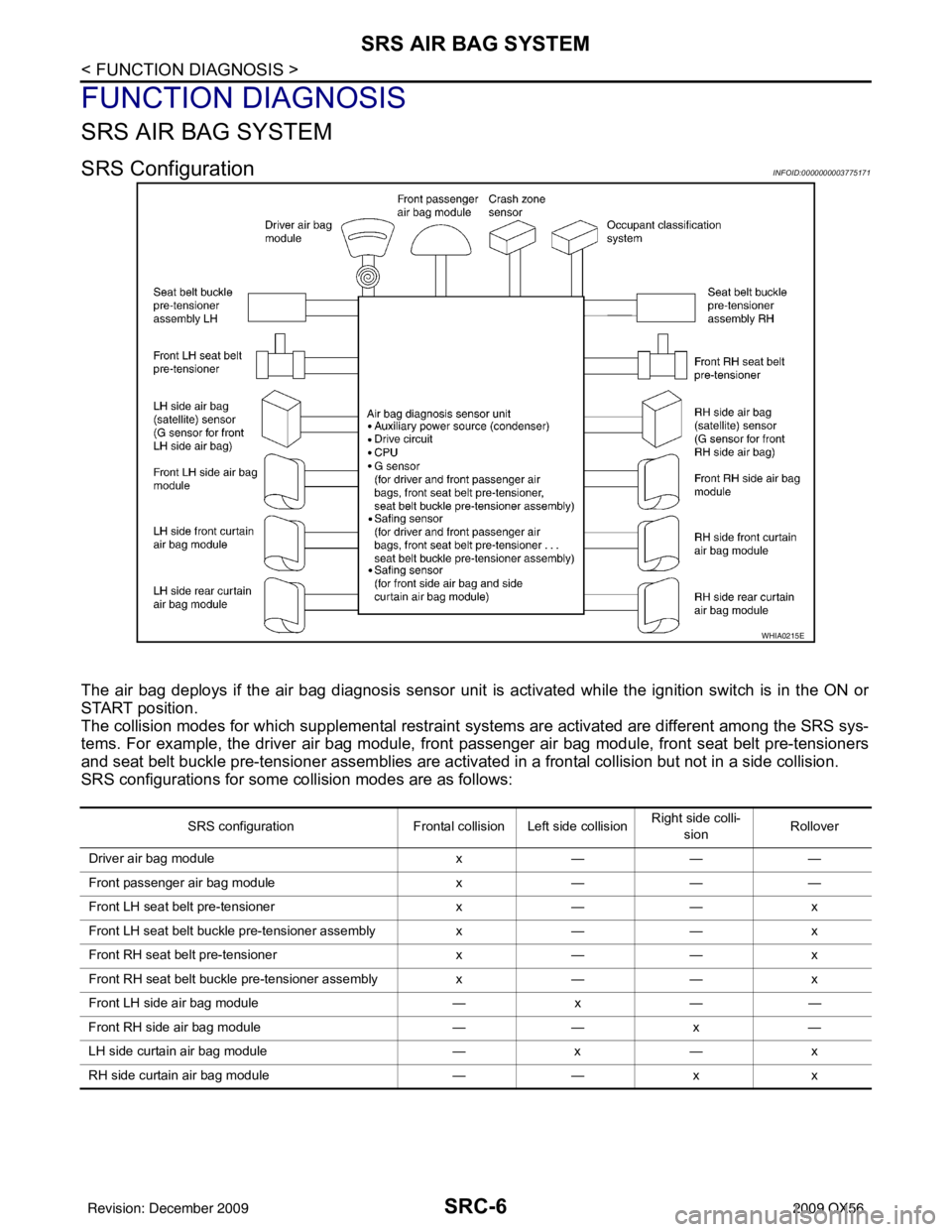
SRS ConfigurationINFOID:0000000003775171
The air bag deploys if the air bag diagnosis sensor unit is activated while the ignition switch is in the ON or
START position.
The collision modes for which supplemental restraint systems are activated are different among the SRS sys-
tems. For example, the driver air bag module, front passenger air bag module, front seat belt pre-tensioners
and seat belt buckle pre-tensioner assemblies are activated in a frontal collision but not in a side collision.
SRS configurations for some collision modes are as follows:
WHIA0215E
SRS configuration Frontal collision Left side collision Right side colli-
sion Rollover
Driver air bag module x— — —
Front passenger air bag module x— — —
Front LH seat belt pre-tensioner x— — x
Front LH seat belt buckle pre-tensioner assembly x— — x
Front RH seat belt pre-tensioner x— — x
Front RH seat belt buckle pre-tensioner assembly x— — x
Front LH side air bag module —x— —
Front RH side air bag module —— x—
LH side curtain air bag module —x— x
RH side curtain air bag module —— xx
Revision: December 20092009 QX56
Page 3505 of 4171

SRS AIR BAG SYSTEMSRC-7
< FUNCTION DIAGNOSIS >
C
DE
F
G
I
J
K L
M A
B
SRC
N
O P
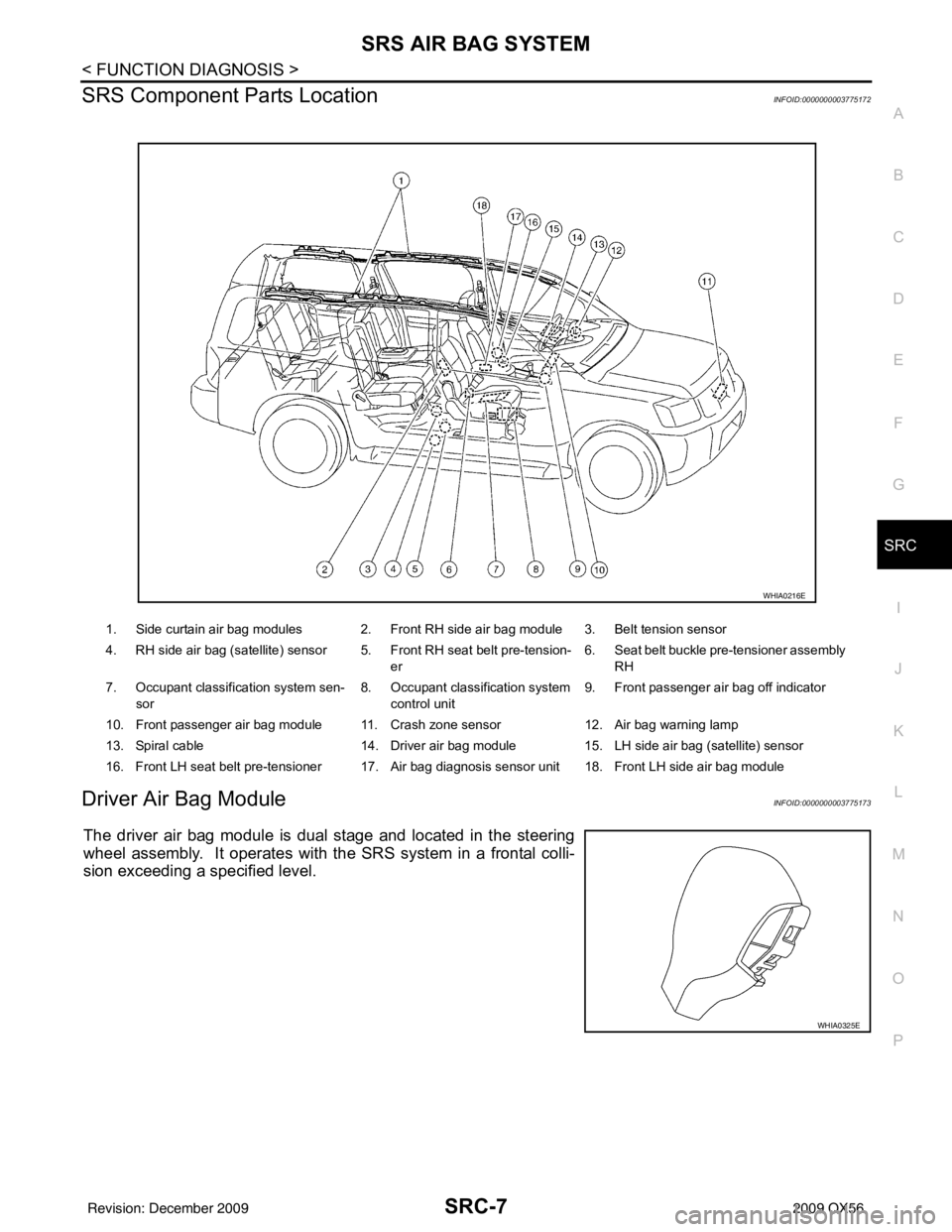
SRS Component Parts LocationINFOID:0000000003775172
Driver Air Bag ModuleINFOID:0000000003775173
The driver air bag module is dual stage and located in the steering
wheel assembly. It operates with the SRS system in a frontal colli-
sion exceeding a specified level.
1. Side curtain air bag modules 2. Front RH side air bag module 3. Belt tension sensor
4. RH side air bag (satellite) sensor 5. Front RH seat belt pre-tension- er6. Seat belt buckle pre-tensioner assembly
RH
7. Occupant classification system sen- sor 8. Occupant classification system
control unit 9. Front passenger air bag off indicator
10. Front passenger air bag module 11. Crash zone sensor 12. Air bag warning lamp
13. Spiral cable 14. Driver air bag module15. LH side air bag (satellite) sensor
16. Front LH seat belt pre-tensioner 17. Air bag diagnosis sensor unit 18. Front LH side air bag module
WHIA0216E
WHIA0325E
Revision: December 20092009 QX56
Page 3506 of 4171

SRC-8
< FUNCTION DIAGNOSIS >
SRS AIR BAG SYSTEM
Front Passenger Air Bag Module
INFOID:0000000003775174
The front passenger air bag module is located behind the instrument
panel assembly. It operates with the SRS system in a frontal colli-
sion exceeding a specified level. Refer to SRC-10, "
Occupant Clas-
sification System (OCS)" for more information.
Front Side Air BagINFOID:0000000003775175
Front side air bag modules are built into the front seatback assem-
blies. Vehicles with side air bags are equipped with labels as shown.
Side Curtain Air BagINFOID:0000000003775176
Side curtain air bag modules are located above the vehicle headlining.
Vehicles with side curtain air bags are equipped with labels as
shown.
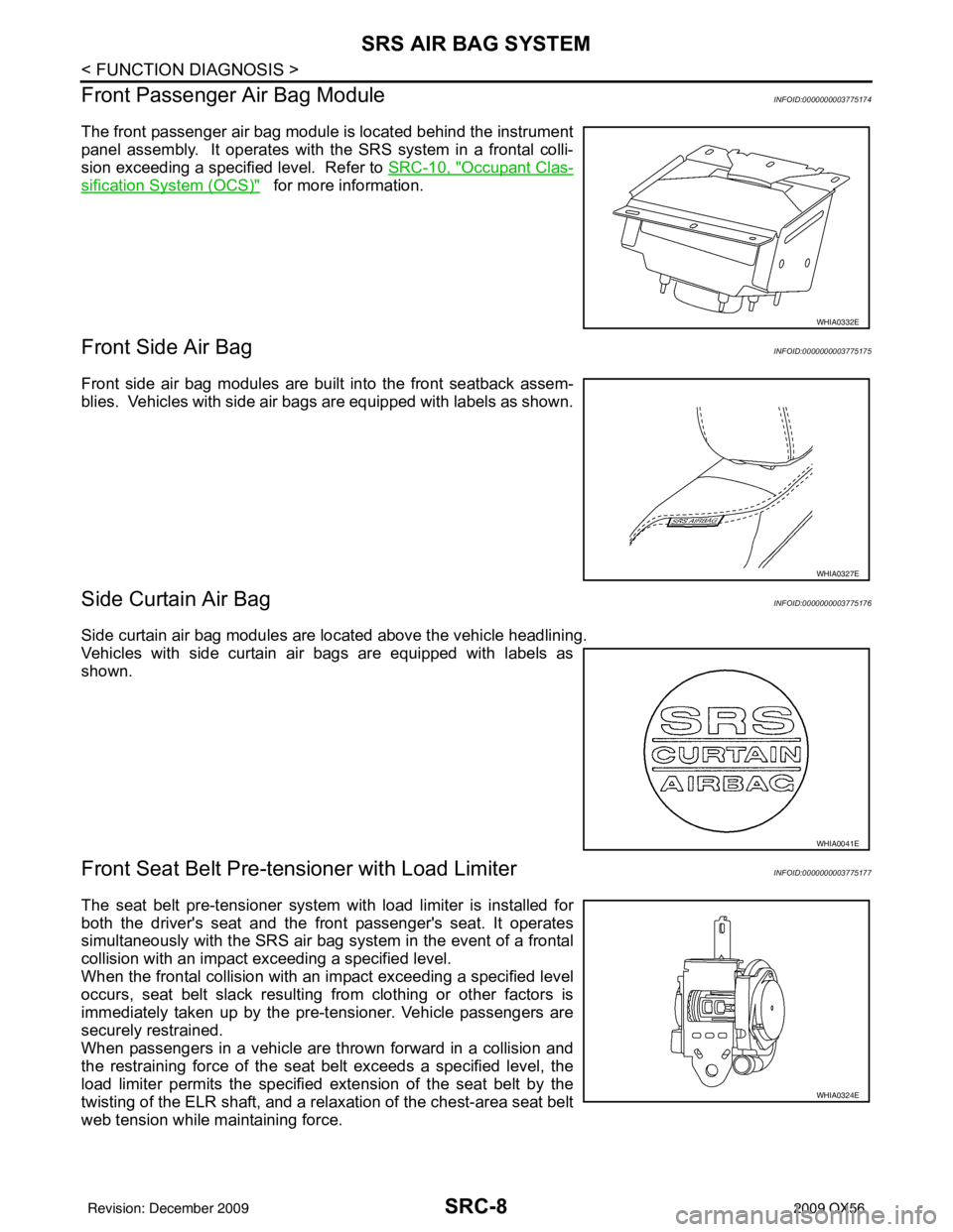
Front Seat Belt Pre-te nsioner with Load LimiterINFOID:0000000003775177
The seat belt pre-tensioner system wi th load limiter is installed for
both the driver's seat and the front passenger's seat. It operates
simultaneously with the SRS air bag system in the event of a frontal
collision with an impact exceeding a specified level.
When the frontal collision with an im pact exceeding a specified level
occurs, seat belt slack resulting from clothing or other factors is
immediately taken up by the pre-tensioner. Vehicle passengers are
securely restrained.
When passengers in a vehicle are thrown forward in a collision and
the restraining force of the seat belt exceeds a specified level, the
load limiter permits the specified extension of the seat belt by the
twisting of the ELR shaft, and a relaxation of the chest-area seat belt
web tension while maintaining force.
WHIA0332E
WHIA0327E
WHIA0041E
WHIA0324E
Revision: December 20092009 QX56
Page 3507 of 4171
SRS AIR BAG SYSTEMSRC-9
< FUNCTION DIAGNOSIS >
C
DE
F
G
I
J
K L
M A
B
SRC
N
O P
Direct-connect SRS Co mponent ConnectorsINFOID:0000000003775178
The following SRS components use dire ct-connect style harness connectors.
• Driver air bag module
• Front passenger air bag module
• LH side front curtain air bag module
• LH side rear curtain air bag module
• RH side front curtain air bag module
• RH side rear curtain air bag module
• Front LH seat belt pre-tensioner
• Front RH seat belt pre-tensioner
• Seat belt buckle pre-tensioner assembly LH
• Seat belt buckle pre-tensioner assembly RH
Always pull up to release locking tab prior to removing connector from SRS component.
Always push down to lock black locking tab after installing connector
to SRS component. When locked, the black locking tab is level with
the connector housing.
WHIA0103E
Revision: December 20092009 QX56