2009 INFINITI QX56 air conditioning
[x] Cancel search: air conditioningPage 1 of 4171

A
B
C
D
E
F
G
H
I
J
K
L
M
N
P
O
QUICK REFERENCE INDEX
AGENERAL INFORMATIONGIGeneral Information
BENGINEEMEngine Mechanical
LUEngine Lubrication System
COEngine Cooling System
ECEngine Control System
FLFuel System
EXExhaust System
STRStarting System
ACCAccelerator Control System
CHYBRIDHBCHybrid Control System
HBBHybrid Battery System
HBRHybrid Brake System
DTRANSMISSION & DRIVE-
LINETMTransaxle & Transmission
DLNDriveline
FAXFront Axle
RAXRear Axle
ESUSPENSIONFSUFront Suspension
RSURear Suspension
SCSSuspension Control System
WTRoad Wheels & Tires
FBRAKESBRBrake System
PBParking Brake System
BRCBrake Control System
GSTEERINGSTSteering System
STCSteering Control System
HRESTRAINTSSBSeat Belt
SBCSeat Belt Control System
SRSRS Airbag
SRCSRS Airbag Control System
IVENTILATION, HEATER &
AIR CONDITIONERVTLVentilation System
HAHeater & Air Conditioning System
HACHeater & Air Conditioning Control System
JBODY INTERIORINTInterior
IPInstrument Panel
SESeat
ADPAutomatic Drive Postioner
APAdjustable Pedal
KBODY EXTERIOR,
DOORS, ROOF & VEHICLE
SECURITYDLKDoor & Lock
SECSecurity Control System
GWGlass & Window System
PWCPower Window Control System
RFRoof
EXTExterior
BRMBody Repair Manual
LDRIVER CONTROLSMIRMirrors
EXLExterior Lighting System
INLInterior Lighting System
WWWiper & Washer
DEFDefogger
HRNHorn
MELECTRICAL & POWER
CONTROLPWOPower Outlet
BCSBody Control System
LANLAN System
PCSPower Control System
CHGCharging System
PGPower Supply, Ground & Circuit Elements
NDRIVER INFORMATION &
MULTIMEDIAMWIMeter, Warning Lamp & Indicator
WCSWarning Chime System
SNSonar System
AVAudio, Visual & Navigation System
OCRUISE CONTROLCCSCruise Control System
PMAINTENANCEMAMaintenance
All rights reserved. No part
of this Service Manual may
be reproduced or stored in a
retrieval system, or transmit-
ted in any form, or by any
means, electronic, mechani-
cal, photo-copying, record-
ing or otherwise, without the
prior written permission of
Nissan North America, Inc.
Edition: June 2008
Revision: December 2009
Publication No. SM9
E-1J60U1
Page 8 of 4171

2009
QUICK REFERNCE CHART: QX56
Front Disc Brake
INFOID:0000000005987155
Unit: mm (in)
Rear Disc BrakeINFOID:0000000005987156
Unit: mm (in)
Fluids and LubricantsINFOID:0000000005987154
Brake model AD41VA
Brake pad Standard thickness (new) 12.0 (0.476)
Repair limit thickness 1.0 (0.039)
Disc rotor Standard thickness (new) 30 (1.181)
Repair limit thickness 28.5 (1.122)
Maximum uneven wear (measured at 8 positions) 0.015 (0.0006)
Runout limit (with it attached to the vehicle) 0.03 (0.001)
Brake model
AD14VE
Brake pad Standard thickness (new) 12.0 (0.472)
Repair limit thickness 1.0 (0.039)
Disc rotor Standard thickness (new) 14.0 (0.551)
Repair limit thickness 12.5 (0.492)
Maximum uneven wear (measured at 8 positions) 0.015 (0.0006)
Runout limit (with it attached to the vehicle) 0.05 (0.002)
Description
Capacity (Approximate)
Metric US measure Imp measure
Fuel 105.8 28 gal 23 1/4 gal
Engine oil
Drain and refill With oil filter change
6.5 6 7/8 qt 5 3/4 qt
Without oil filter change 6.2 6 1/2 qt 5 1/2 qt
Dry engine (engine overhaul) 7.6 8 qt 6 3/4 qt
Cooling system With reservoir
at MAX level
14.4
15 1/4 qt 12 5/8 qt
Automatic transmission fluid (ATF) 10.6 11 1/4 qt 9 3/8 qt
Rear differential gear oil 1.75 3 3/4 pt 3 1/8 pt
Transfer fluid 3.0 3 1/8 qt 2 5/8 qt
Front differential gear oil 1.6 3 3/8 pt 2 7/8 pt
Power steering fluid (PSF) 1.0 1 1/8 qt 7/8 qt
Brake fluid — — —
Brake grease — — —
Multi-purpose grease — — —
Windshield washer fluid 4.5 4 3/4 qt 4 qt
Air conditioning system refrigerant 1.08 ± 0.05 kg 2.38 ± 0.11 lb 2.38 ± 0.11 lb
Air conditioning system oil 290 m9.8 fl oz 10.2 fl oz
Page 1328 of 4171

EC-1
ENGINE
C
DE
F
G H
I
J
K L
M
SECTION EC
A
EC
N
O P
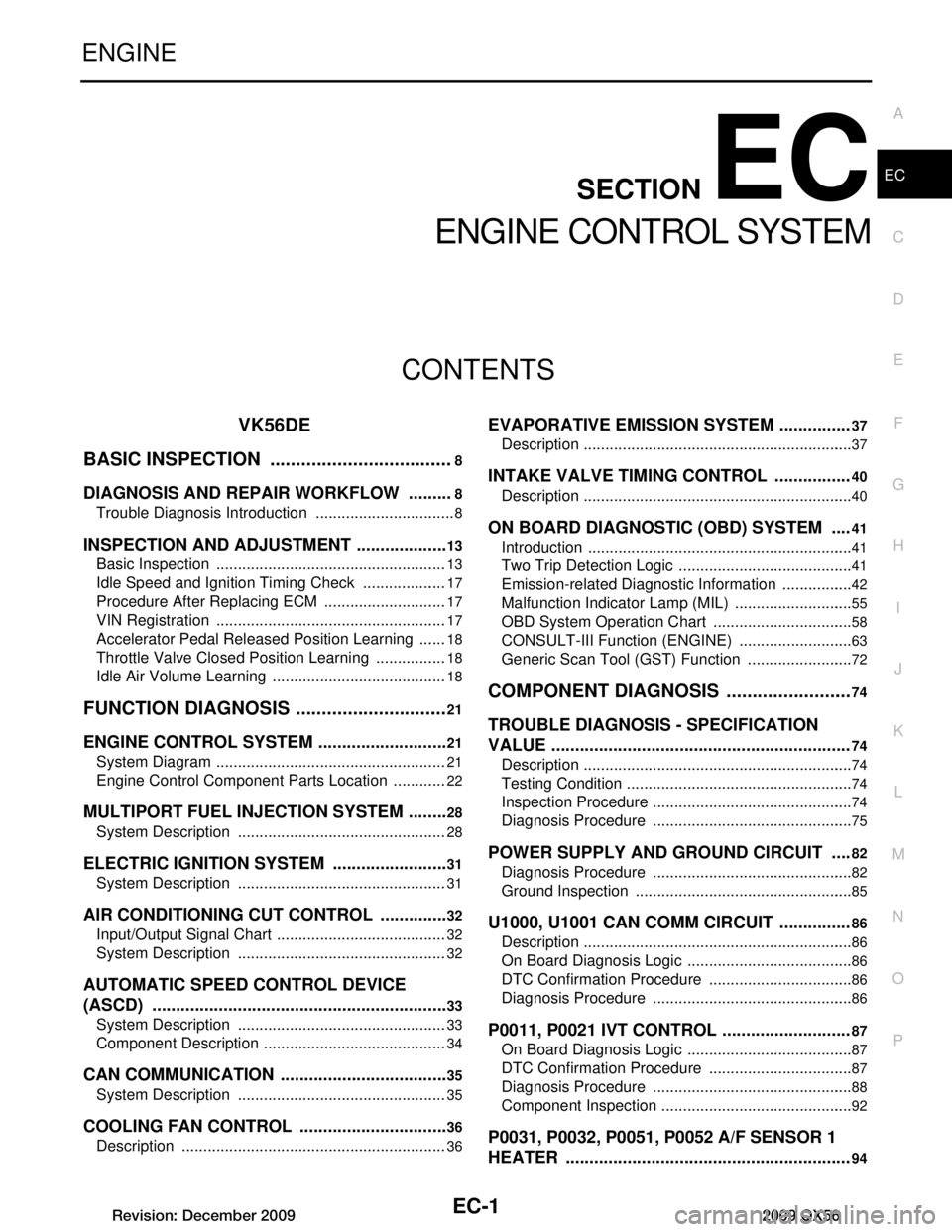
CONTENTS
ENGINE CONTROL SYSTEM
VK56DE
BASIC INSPECTION ....... .............................
8
DIAGNOSIS AND REPAIR WORKFLOW ..... .....8
Trouble Diagnosis Introduction ........................... ......8
INSPECTION AND ADJUSTMENT ....................13
Basic Inspection .................................................. ....13
Idle Speed and Ignition Timing Check ....................17
Procedure After Replacing ECM .............................17
VIN Registration ......................................................17
Accelerator Pedal Released Position Learning .......18
Throttle Valve Closed Position Learning .................18
Idle Air Volume Learning .........................................18
FUNCTION DIAGNOSIS ..............................21
ENGINE CONTROL SYSTEM ........................ ....21
System Diagram .................................................. ....21
Engine Control Component Parts Location .............22
MULTIPORT FUEL INJECTION SYSTEM .........28
System Description ............................................. ....28
ELECTRIC IGNITION SYSTEM ..................... ....31
System Description ............................................. ....31
AIR CONDITIONING CUT CONTROL ...............32
Input/Output Signal Chart .................................... ....32
System Description .................................................32
AUTOMATIC SPEED CONTROL DEVICE
(ASCD) ...............................................................
33
System Description ............................................. ....33
Component Description ...........................................34
CAN COMMUNICATION ....................................35
System Description ............................................. ....35
COOLING FAN CONTROL ................................36
Description .......................................................... ....36
EVAPORATIVE EMISSION SYSTEM ...............37
Description ........................................................... ....37
INTAKE VALVE TIMING CONTROL ................40
Description ...............................................................40
ON BOARD DIAGNOSTIC (OBD) SYSTEM ....41
Introduction ..............................................................41
Two Trip Detection Logic .........................................41
Emission-related Diagnostic Information .................42
Malfunction Indicator Lamp (MIL) ............................55
OBD System Operation Chart .................................58
CONSULT-III Function (ENGINE) ...........................63
Generic Scan Tool (GST) Function .........................72
COMPONENT DIAGNOSIS .........................74
TROUBLE DIAGNOSIS - SPECIFICATION
VALUE ...............................................................
74
Description ........................................................... ....74
Testing Condition .....................................................74
Inspection Procedure ...............................................74
Diagnosis Procedure ...............................................75
POWER SUPPLY AND GROUND CIRCUIT ....82
Diagnosis Procedure ...............................................82
Ground Inspection ...................................................85
U1000, U1001 CAN COMM CIRCUIT ...............86
Description ...............................................................86
On Board Diagnosis Logic .......................................86
DTC Confirmation Procedure ..................................86
Diagnosis Procedure ...............................................86
P0011, P0021 IVT CONTROL ...........................87
On Board Diagnosis Logic .......................................87
DTC Confirmation Procedure ..................................87
Diagnosis Procedure ...............................................88
Component Inspection .............................................92
P0031, P0032, P0051, P0052 A/F SENSOR 1
HEATER ............................................................
94
Revision: December 20092009 QX56
Page 1359 of 4171
![INFINITI QX56 2009 Factory Service Manual
EC-32
< FUNCTION DIAGNOSIS >[VK56DE]
AIR CONDITIONING CUT CONTROL
AIR CONDITIONING CUT CONTROL
Input/Output Signal ChartINFOID:0000000003771305
*1: This signal is sent to the ECM through CAN communic INFINITI QX56 2009 Factory Service Manual
EC-32
< FUNCTION DIAGNOSIS >[VK56DE]
AIR CONDITIONING CUT CONTROL
AIR CONDITIONING CUT CONTROL
Input/Output Signal ChartINFOID:0000000003771305
*1: This signal is sent to the ECM through CAN communic](/manual-img/42/57031/w960_57031-1358.png)
EC-32
< FUNCTION DIAGNOSIS >[VK56DE]
AIR CONDITIONING CUT CONTROL
AIR CONDITIONING CUT CONTROL
Input/Output Signal ChartINFOID:0000000003771305
*1: This signal is sent to the ECM through CAN communication line.
*2: ECM determines the start signal status by the signals of engine speed and battery voltage.
System DescriptionINFOID:0000000003771306
This system improves engine operati
on when the air conditioner is used.
Under the following conditions, the air conditioner is turned OFF.
When the accelerator pedal is fully depressed.
When cranking the engine.
At high engine speeds.
When the engine coolant temperature becomes excessively high.
When operating power steering during low engine speed or low vehicle speed.
When engine speed is excessively low.
When refrigerant pressure is excessively low or high.
Sensor Input Signal to ECM ECM function Actuator
Air conditioner switch Air conditioner ON signal*
1
Air conditioner
cut controlAir conditio
ner relay
Accelerator pedal position sensor Accelerator pedal position
Crankshaft position sensor (POS)
Camshaft position sensor (PHASE)
Engine speed*
2
Engine coolant temperature sensor Engine coolant temperature
Battery
Battery voltage*
2
Refrigerant pressure sensor Refrigerant pressure
Power steering pressure sensor Power steering operation
Wheel sensor
Vehicle speed*
1
Revision: December 20092009 QX56
Page 1607 of 4171
![INFINITI QX56 2009 Factory Service Manual
EC-280
< COMPONENT DIAGNOSIS >[VK56DE]
P0603 ECM POWER SUPPLY
P0603 ECM POWER SUPPLY
DescriptionINFOID:0000000003771559
Battery voltage is supplied to the ECM even when the ignition switch
is turned INFINITI QX56 2009 Factory Service Manual
EC-280
< COMPONENT DIAGNOSIS >[VK56DE]
P0603 ECM POWER SUPPLY
P0603 ECM POWER SUPPLY
DescriptionINFOID:0000000003771559
Battery voltage is supplied to the ECM even when the ignition switch
is turned](/manual-img/42/57031/w960_57031-1606.png)
EC-280
< COMPONENT DIAGNOSIS >[VK56DE]
P0603 ECM POWER SUPPLY
P0603 ECM POWER SUPPLY
DescriptionINFOID:0000000003771559
Battery voltage is supplied to the ECM even when the ignition switch
is turned OFF for the ECM memory function of the DTC memory, the
air-fuel ratio feedback compensation value memory, the idle air vol-
ume learning value memory, etc.
DTC LogicINFOID:0000000005867524
DTC DETECTION LOGIC
DTC CONFIRMATION PROCEDURE
1.PRECONDITIONING
If DTC Confirmation Procedure has been previously conducted, always perform the following before conduct-
ing the next test.
1. Turn ignition switch OFF and wait at least 10 seconds.
2. Turn ignition switch ON.
3. Turn ignition switch OFF and wait at least 10 seconds.
>> GO TO 2.
2.PERFORM DTC CONFIRMATION PROCEDURE
1. Turn ignition switch ON and wait at least 10 seconds.
2. Turn ignition switch OFF and wait at least 5 minutes
3. Turn ignition switch ON and wait at least 10 seconds.
4. Repeat steps 2 and 3 for five more times.
5. Check 1st trip DTC.
Is 1st trip DTC detected?
YES >> Go to EC-280, "Diagnosis Procedure".
NO >> INSPECTION END
Diagnosis ProcedureINFOID:0000000003771562
1.CHECK ECM POWER SUPPLY
1. Turn ignition switch OFF.
2. Disconnect ECM harness connector.
PBIB1164E
DTC No. Trouble diagnosis name DTC detecting condition Possible cause
P0603
0603 ECM power supply cir-
cuit ECM backup RAM system does not function
properly. Harness or connectors
[ECM power supply (backup) circuit is
open or shorted.]
Low battery voltage
Battery disconnected
ECM
Revision: December 20092009 QX56
Page 2195 of 4171

GI-1
GENERAL INFORMATION
C
DE
F
G H
I
J
K L
M B
GI
SECTION GI
N
O P
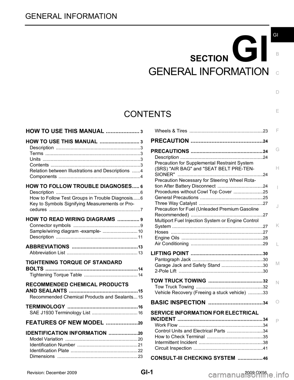
CONTENTS
GENERAL INFORMATION
HOW TO USE THIS MANU AL ......................3
HOW TO USE THIS MANUAL ....................... .....3
Description .......................................................... ......3
Terms ........................................................................3
Units ..........................................................................3
Contents ....................................................................3
Relation between Illustrations and Descriptions .......4
Components ..............................................................4
HOW TO FOLLOW TROUBLE DIAGNOSES .....6
Description ................................................................6
How to Follow Test Groups in Trouble Diagnosis ......6
Key to Symbols Signifying Measurements or Pro-
cedures ............................................................... ......
7
HOW TO READ WIRING DIAGRAMS ................9
Connector symbols ............................................. ......9
Sample/wiring diagram -example- ...........................10
Description ..............................................................11
ABBREVIATIONS .......................................... ....13
Abbreviation List .................................................. ....13
TIGHTENING TORQUE OF STANDARD
BOLTS ................................................................
14
Tightening Torque Table .........................................14
RECOMMENDED CHEMICAL PRODUCTS
AND SEALANTS ............................................ ....
15
Recommended Chemical Products and Sealants ....15
TERMINOLOGY .................................................16
SAE J1930 Terminology List ............................... ....16
FEATURES OF NEW MODEL .....................20
IDENTIFICATION INFORMATION .....................20
Model Variation ................................................... ....20
Identification Number ..............................................21
Identification Plate ...................................................22
Dimensions .............................................................23
Wheels & Tires .................................................... ....23
PRECAUTION ..............................................24
PRECAUTIONS .................................................24
Description ........................................................... ....24
Precaution for Supplemental Restraint System
(SRS) "AIR BAG" and "SEAT BELT PRE-TEN-
SIONER" .................................................................
24
Precaution Necessary for Steering Wheel Rota-
tion After Battery Disconnect ...................................
24
Procedures without Cowl Top Cover .......................25
General Precautions ................................................25
Three Way Catalyst .................................................27
Precaution for Fuel (Unleaded Premium Gasoline
Recommended) .......................................................
27
Multiport Fuel Injection System or Engine Control
System .....................................................................
27
Hoses ......................................................................27
Engine Oils ..............................................................28
Air Conditioning .......................................................29
LIFTING POINT .................................................30
Pantograph Jack ......................................................30
Garage Jack and Safety Stand ................................30
2-Pole Lift ................................................................30
TOW TRUCK TOWING .....................................32
Tow Truck Towing ...................................................32
Vehicle Recovery (Freeing a stuck vehicle) ............33
BASIC INSPECTION ...................................34
SERVICE INFORMATION FOR ELECTRICAL
INCIDENT ..........................................................
34
Work Flow ............................................................ ....34
Control Units and Electrical Parts ............................34
How to Check Terminal ...........................................35
Intermittent Incident ............................................. ....38
Circuit Inspection .....................................................41
CONSULT-III CHECKING SYSTEM .................46
Revision: December 20092009 QX56
Page 2215 of 4171

IDENTIFICATION INFORMATIONGI-21
< FEATURES OF NEW MODEL >
C
DE
F
G H
I
J
K L
M B
GI
N
O P
Identification NumberINFOID:0000000003771190
VEHICLE IDENTIFICATION NUMBER ARRANGEMENT
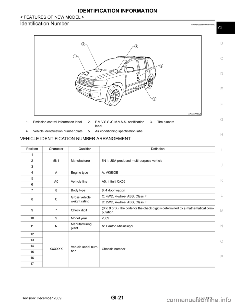
1. Emission control information label 2. F.M.V.S.S./C.M.V.S.S. certification label 3. Tire placard
4. Vehicle identification number plate 5. Air conditioning specfication label
AWAIA0026GB
Position Character Qualifier Definition
1 5N1 Manufacturer 5N1: USA produced multi-purpose vehicle
2
3
4 A Engine type A: VK56DE
5 A0 Vehicle line A0: Infiniti QX56
6
7 8 Body type 8: 4 door wagon
8C Gross vehicle
weight ratingC: 4WD, 4-wheel ABS, Class F
D: 2WD, 4-wheel ABS, Class F
9 * Check digit (0 to 9 or X) The code for the check digit is determined by a mathematical com-
putation.
10 9 Model year 2009
11 NManufacturing
plant
N: Canton Mississippi
12
XXXXXX Vehicle serial num-
ber Chassis number
13
14
15
16
17
Revision: December 20092009 QX56
Page 2223 of 4171

PRECAUTIONSGI-29
< PRECAUTION >
C
DE
F
G H
I
J
K L
M B
GI
N
O P
Dispose of used oil and used oil filters through authorized waste disposal contractors to licensed waste dis-
posal sites, or to the waste oil reclamation trade. If in doubt, contact the local authority for advice on disposal
facilities.
It is illegal to pour used oil on to the ground, down sewers or drains, or into water sources.
The regulations concerning po llution vary between regions.
Air ConditioningINFOID:0000000003771205
Use an approved refrigerant recovery unit any time t he air conditioning system must be discharged. Refer to
HA-20, "
HFC-134a (R-134a) Service Procedure".
Revision: December 20092009 QX56