2009 INFINITI QX56 light
[x] Cancel search: lightPage 2446 of 4171

INL-2
DTC Index ..............................................................68
SYMPTOM DIAGNOSIS .............................70
INTERIOR LIGHTING SYSTEM SYMPTOMS ...70
Symptom Table ................................................... ...70
PRECAUTION .............................................71
PRECAUTIONS .............................................. ...71
Precaution for Supplemental Restraint System
(SRS) "AIR BAG" and "SEAT BELT PRE-TEN-
SIONER" .............................................................. ...
71
Precaution Necessary for Steering Wheel Rota-
tion After Battery Disconnect ..................................
71
General precautions for service operations ......... ...72
ON-VEHICLE REPAIR ...............................73
INTERIOR ROOM LAMP ................................ ...73
Removal and Installation .........................................73
ILLUMINATION .............................................. ...77
Removal and Installation .........................................77
SERVICE DATA AND SPECIFICATIONS
(SDS) .......... ................................. ...............
79
BULB SPECIFICATIONS ............................... ...79
Interior Lamp/Illumination ........................................79
Revision: December 20092009 QX56
Page 2453 of 4171

ILLUMINATION CONTROL SYSTEMINL-9
< FUNCTION DIAGNOSIS >
C
DE
F
G H
I
J
K
M A
B
INL
N
O P
ILLUMINATION CONTROL SYSTEM
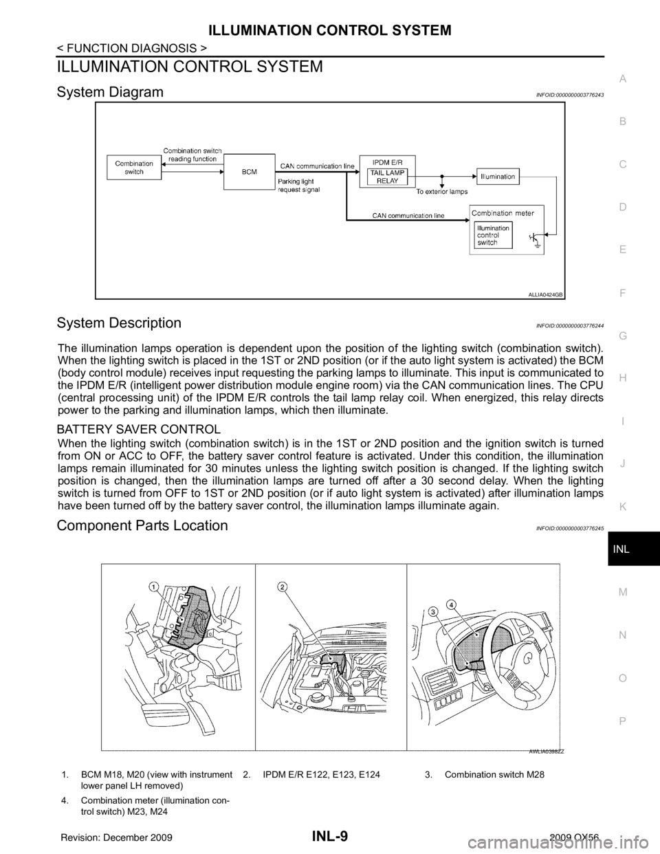
System DiagramINFOID:0000000003776243
System DescriptionINFOID:0000000003776244
The illumination lamps operation is dependent upon the posit ion of the lighting switch (combination switch).
When the lighting switch is placed in the 1ST or 2ND posit ion (or if the auto light system is activated) the BCM
(body control module) receives input requesting the park ing lamps to illuminate. This input is communicated to
the IPDM E/R (intelligent power distribution module engine room) via the CAN communication lines. The CPU
(central processing unit) of the IPDM E/R controls the tail lamp relay coil. When energized, this relay directs
power to the parking and illumination lamps, which then illuminate.
BATTERY SAVER CONTROL
When the lighting switch (combination switch) is in t he 1ST or 2ND position and the ignition switch is turned
from ON or ACC to OFF, the battery saver control feat ure is activated. Under this condition, the illumination
lamps remain illuminated for 30 minutes unless the light ing switch position is changed. If the lighting switch
position is changed, then the illumination lamps are turned off after a 30 second delay. When the lighting
switch is turned from OFF to 1ST or 2ND position (or if auto light system is activated) after illumination lamps
have been turned off by the battery saver control, the illumination lamps illuminate again.
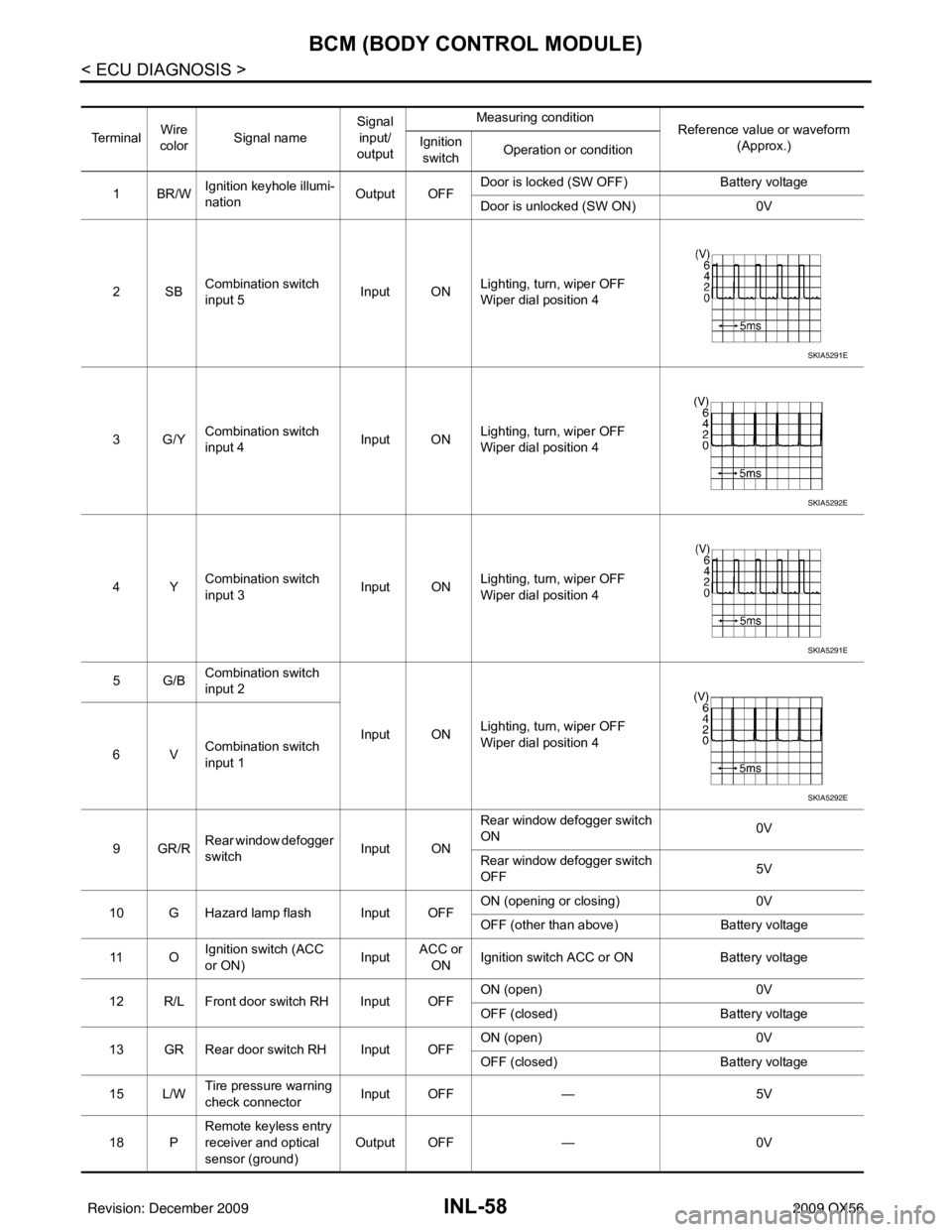
Component Parts LocationINFOID:0000000003776245
ALLIA0424GB
1. BCM M18, M20 (view with instrument
lower panel LH removed) 2. IPDM E/R E122, E123, E124 3. Combination switch M28
4. Combination meter (illumination con- trol switch) M23, M24
AWLIA0398ZZ
Revision: December 20092009 QX56
Page 2454 of 4171

INL-10
< FUNCTION DIAGNOSIS >
ILLUMINATION CONTROL SYSTEM
Component Description
INFOID:0000000003776246
Part name Description
BCM The BCM monitors the lighting switch position with the combina-
tion switch reading function. The BCM requests, via CAN com-
munication, that the IPDM E/R activate the tail lamp relay.
IPDM E/R The IPDM E/R activates the tail lamp relay based on inputs re-
ceived from the BCM via the CAN communication network.
Combination meter (illumination control switch) The illumination control switch is a part of the combination meter.
The combination meter controls illumination intensity by varying
ground to the illumination lamps based on the illumination control
switch position.
Combination switch The combination switch provides input to the BCM about the light-
ing switch position.
Revision: December 20092009 QX56
Page 2499 of 4171

BCM (BODY CONTROL MODULE)INL-55
< ECU DIAGNOSIS >
C
DE
F
G H
I
J
K
M A
B
INL
N
O P
ECU DIAGNOSIS
BCM (BODY CONTROL MODULE)
Reference ValueINFOID:0000000004109551
VALUES ON THE DIAGNOSIS TOOL
Monitor Item Condition Value/Status
AIR COND SW A/C switch OFF
OFF
A/C switch ON ON
AUT LIGHT SYS Outside of the room is dark
OFF
Outside of the room is bright ON
AUTO LIGHT SW Lighting switch OFF
OFF
Lighting switch AUTO ON
BACK DOOR SW Back door closed
OFF
Back door opened ON
CDL LOCK SW Door lock/unlock switch does not operate
OFF
Press door lock/unlock switch to the LOCK side ON
CDL UNLOCK SW Door lock/unlock switch does not operate
OFF
Press door lock/unlock switch to the UNLOCK side ON
DOOR SW-AS Front door RH closed
OFF
Front door RH opened ON
DOOR SW-DR Front door LH closed
OFF
Front door LH opened ON
DOOR SW-RL Rear door LH closed
OFF
Rear door LH opened ON
DOOR SW-RR Rear door RH closed
OFF
Rear door RH opened ON
ENGINE RUN Engine stopped
OFF
Engine running ON
FR FOG SW Front fog lamp switch OFF
OFF
Front fog lamp switch ON ON
FR WASHER SW Front washer switch OFF
OFF
Front washer switch ON ON
FR WIPER LOW Front wiper switch OFF
OFF
Front wiper switch LO ON
FR WIPER HI Front wiper switch OFF
OFF
Front wiper switch HI ON
FR WIPER INT Front wiper switch OFF
OFF
Front wiper switch INT ON
FR WIPER STOP Any position other than front wiper stop position
OFF
Front wiper stop position ON
HAZARD SW When hazard switch is not pressed
OFF
When hazard switch is pressed ON
LIGHT SW 1ST Lighting switch OFF
OFF
Lighting switch 1st ON
Revision: December 20092009 QX56
Page 2500 of 4171

INL-56
< ECU DIAGNOSIS >
BCM (BODY CONTROL MODULE)
HEADLAMP SW1Headlamp switch OFF OFF
Headlamp switch 1st
ON
HEADLAMP SW2 Headlamp switch OFF
OFF
Headlamp switch 1st ON
HI BEAM SW High beam switch OFF
OFF
High beam switch HI ON
H/L WASH SW NOTE:
The item is indicated, but not monitored OFF
IGN ON SW Ignition switch OFF or ACC
OFF
Ignition switch ON ON
IGN SW CAN Ignition switch OFF or ACC
OFF
Ignition switch ON ON
INT VOLUME Wiper intermittent dial is in a dial position 1 - 7 1 - 7
I-KEY LOCK LOCK button of Intelligent Key is not pressed
OFF
LOCK button of Intelligent Key is pressed ON
I-KEY UNLOCK UNLOCK button of Intelligent Key is not pressed
OFF
UNLOCK button of Intelligent Key is pressed ON
KEY ON SW Mechanical key is removed from key cylinder
OFF
Mechanical key is inserted to key cylinder ON
OIL PRESS SW • Ignition switch OFF or ACC
• Engine running
OFF
Ignition switch ON ON
PASSING SW Other than lighting switch PASS
OFF
Lighting switch PASS ON
REAR DEF SW Rear window defogger switch OFF
OFF
Rear window defogger switch ON ON
RKE LOCK AND UN-
LOCK NOTE:
The item is indicated, but not monitored OFF
ON
RR WASHER SW Rear washer switch OFF
OFF
Rear washer switch ON ON
RR WIPER INT Rear wiper switch OFF
OFF
Rear wiper switch INT ON
RR WIPER ON Rear wiper switch OFF
OFF
Rear wiper switch ON ON
RR WIPER STOP Rear wiper stop position
OFF
Other than rear wiper stop position ON
TAIL LAMP SW Lighting switch OFF
OFF
Lighting switch 1ST ON
TRNK OPNR SW When back door opener switch is not pressed
OFF
When back door opener switch is pressed ON
TURN SIGNAL L Turn signal switch OFF
OFF
Turn signal switch LH ON
TURN SIGNAL R Turn signal switch OFF
OFF
Turn signal switch RH ON
VEHICLE SPEED While driving Equivalent to speedometer reading
Monitor Item
Condition Value/Status
Revision: December 20092009 QX56
Page 2502 of 4171

INL-58
< ECU DIAGNOSIS >
BCM (BODY CONTROL MODULE)
Te r m i n a lWire
color Signal name Signal
input/
output Measuring condition
Reference value or waveform
(Approx.)
Ignition
switch Operation or condition
1BR/W Ignition keyhole illumi-
nation Output OFFDoor is locked (SW OFF)
Battery voltage
Door is unlocked (SW ON) 0V
2SB Combination switch
input 5 Input ON
Lighting, turn, wiper OFF
Wiper dial position 4
3G/Y Combination switch
input 4 Input ONLighting, turn, wiper OFF
Wiper dial position 4
4Y Combination switch
input 3 Input ON
Lighting, turn, wiper OFF
Wiper dial position 4
5G/B Combination switch
input 2
Input ONLighting, turn, wiper OFF
Wiper dial position 4
6V Combination switch
input 1
9GR/R Rear window defogger
switch
Input ONRear window defogger switch
ON
0V
Rear window defogger switch
OFF 5V
10 G Hazard lamp flash Input OFF ON (opening or closing)
0V
OFF (other than above) Battery voltage
11 O Ignition switch (ACC
or ON)
InputACC or
ON Ignition switch ACC or ON
Battery voltage
12 R/L Front door switch RH Input OFF ON (open)
0V
OFF (closed) Battery voltage
13 GR Rear door switch RH Input OFF ON (open)
0V
OFF (closed) Battery voltage
15 L/W Tire pressure warning
check connector
Input OFF
—5V
18 P Remote keyless entry
receiver and optical
sensor (ground)
Output OFF
—0V
SKIA5291E
SKIA5292E
SKIA5291E
SKIA5292E
Revision: December 20092009 QX56
Page 2504 of 4171

INL-60
< ECU DIAGNOSIS >
BCM (BODY CONTROL MODULE)
28 L/R Front blower monitor Input ONFront blower motor OFF
Battery voltage
Front blower motor ON 0V
29 W/B Hazard switch Input OFFON
0V
OFF 5V
30 Y/BR Glass hatch switch Input OFF Glass hatch switch released
0
Glass hatch switch pressed Battery
32 R/G Combination switch
output 5
Output ONLighting, turn, wiper OFF
Wiper dial position 4
33 R/Y Combination switch
output 4 Output ONLighting, turn, wiper OFF
Wiper dial position 4
34 L Combination switch
output 3 Output ON
Lighting, turn, wiper OFF
Wiper dial position 4
35 O/B Combination switch
output 2
Output ONLighting, turn, wiper OFF
Wiper dial position 4
36 R/W Combination switch
output 1
37 B/R Key switch and igni-
tion knob switch Input OFFIntelligent Key inserted
Battery voltage
Intelligent Key inserted 0V
38 W/L Ignition switch (ON) Input ON —Battery voltage
39 L CAN-H — —— —
40 P CAN-L — —— —
42 GR Glass hatch ajar
switch Input ONGlass hatch open
0
Glass hatch closed Battery
43 R/B Back door latch (door
ajar switch) Input OFFON (open)
0V
OFF (closed) Battery voltage
Te r m i n a l
Wire
color Signal name Signal
input/
output Measuring condition
Reference value or waveform
(Approx.)
Ignition
switch Operation or condition
SKIA5291E
SKIA5292E
SKIA5291E
SKIA5292E
Revision: December 20092009 QX56
Page 2514 of 4171

INL-70
< SYMPTOM DIAGNOSIS >
INTERIOR LIGHTING SYSTEM SYMPTOMS
SYMPTOM DIAGNOSIS
INTERIOR LIGHTING SYSTEM SYMPTOMS
Symptom TableINFOID:0000000003776269
CAUTION:
Perform the self-diagnosis with CONSULT-III before the symptom diagnosis. Perform the trouble diag-
nosis if any DTC is detected.
Symptom Possible causeInspection item
All of the following lamps do not turn ON
• Front room/map lamp assembly
• Personal lamp 2nd and 3rd row
• Cargo room lamp
• Front and rear step lamps
• Vanity mirror lamps
• Ignition keyhole illumination
• Puddle lamps
•Foot lamps • Harness between BCM and each
interior room lamp
•BCM Battery saver output/power supply
circuit
Refer to
INL-15
.
Some or all of the following interior room lamps do not
turn ON/OFF
• Puddle lamps
• Front room/map lamp assembly
• Personal lamp 2nd row
• Personal lamp 3rd row • Harness between BCM and each
door switch
• Harness between BCM and each interior room lamp
•BCM Door switch circuit
Refer to
DLK-71
.
Interior room lamp control circuit
Refer to INL-17
.
Some or all of the following lamps do not turn ON/OFF
• Front step lamps
• Rear step lamps
•Foot lamps • Harness between BCM and step
lamps and foot lamps
•BCM Step lamp circuit
Refer to
INL-19
.
Cargo lamp does not turn ON/OFF • Harness between BCM and cargo
lamp
•BCM Cargo lamp co
ntrol circuit
Refer to INL-21
.
Ignition keyhole illumination does not turn ON/OFF • Harness between BCM and ignition
keyhole illumination
•BCM Ignition keyhole illumination control
circuit
Refer to
INL-23
.
Interior room lamp timer does not activate.
(It turns ON/ OFF when the door opens/closes.) —Check the interior room lamp setting.
Refer to
INL-12
.
Interior room lamp battery saver does not activate. —Check the interior room lamp battery
saver setting.
Refer to
INL-13
.
Revision: December 20092009 QX56