2009 INFINITI QX56 light
[x] Cancel search: lightPage 2553 of 4171

SQUEAK AND RATTLE TROUBLE DIAGNOSESIP-9
< SYMPTOM DIAGNOSIS >
C
DE
F
G H
I
K L
M A
B
IP
N
O P
2. Trunk lid striker out of adjustment
3. The trunk lid torsion bars knocking together
4. A loose license plate or bracket
Most of these incidents can be repaired by adjusting, se curing or insulating the item(s) or component(s) caus-
ing the noise.
SUNROOF/HEADLINING
Noises in the sunroof/headlining area can often be traced to one of the following:
1. Sunroof lid, rail, linkage or seals making a rattle or light knocking noise
2. Sun visor shaft shaking in the holder
3. Front or rear windshield touching headliner and squeaking
Again, pressing on the components to stop the noise while duplicating the conditions can isolate most of these
incidents. Repairs usually consist of insulating with felt cloth tape.
OVERHEAD CONSOLE (FRONT AND REAR)
Overhead console noises are often caused by the cons ole panel clips not being engaged correctly. Most of
these incidents are repaired by pushing up on the c onsole at the clip locations until the clips engage.
In addition look for:
1. Loose harness or harness connectors.
2. Front console map/reading lamp lens loose.
3. Loose screws at console attachment points.
SEATS
When isolating seat noise it's important to note the position the seat is in and the load placed on the seat when
the noise is present. These conditions should be duplicated when verifying and isolating the cause of the
noise.
Cause of seat noise include:
1. Headrest rods and holder
2. A squeak between the seat pad cushion and frame
3. The rear seatback lock and bracket
These noises can be isolated by moving or pressing on the suspected components while duplicating the con-
ditions under which the noise occurs. Most of thes e incidents can be repaired by repositioning the component
or applying urethane tape to the contact area.
UNDERHOOD
Some interior noise may be caused by components under the hood or on the engine wall. The noise is then
transmitted into the passenger compartment.
Causes of transmitted underhood noise include:
1. Any component mounted to the engine wall
2. Components that pass through the engine wall
3. Engine wall mounts and connectors
4. Loose radiator mounting pins
5. Hood bumpers out of adjustment
6. Hood striker out of adjustment
These noises can be difficult to isolate since they cannot be reached from the interior of the vehicle. The best
method is to secure, move or insulate one component at a time and test drive the vehicle. Also, engine RPM
or load can be changed to isolate the noise. Repairs can usually be made by moving, adjusting, securing, or
insulating the component causing the noise.
Revision: December 20092009 QX56
Page 2614 of 4171
![INFINITI QX56 2009 Factory Service Manual LAN
CAN COMMUNICATION SYSTEMLAN-45
< FUNCTION DIAGNOSIS > [CAN]
C
D
E
F
G H
I
J
K L
B A
O P
N
Engine speed signal
T RRR R R R R R
Engine status signal TR
Fuel consumption monitor signal TR
RT
ICC stee INFINITI QX56 2009 Factory Service Manual LAN
CAN COMMUNICATION SYSTEMLAN-45
< FUNCTION DIAGNOSIS > [CAN]
C
D
E
F
G H
I
J
K L
B A
O P
N
Engine speed signal
T RRR R R R R R
Engine status signal TR
Fuel consumption monitor signal TR
RT
ICC stee](/manual-img/42/57031/w960_57031-2613.png)
LAN
CAN COMMUNICATION SYSTEMLAN-45
< FUNCTION DIAGNOSIS > [CAN]
C
D
E
F
G H
I
J
K L
B A
O P
N
Engine speed signal
T RRR R R R R R
Engine status signal TR
Fuel consumption monitor signal TR
RT
ICC steering switch signal TR
Malfunction indicator lamp signal T R
Wide open throttle position signal T R
A/T CHECK indicato r lamp signal T R
A/T fluid temperature sensor signal T R
A/T position indicator lamp signal TR RR
A/T self-diagnosis signal R T
Current gear position signal TR R
Input speed signal R TR
Output shaft revolution signal R TR R
P range signal TR R RR
ICC sensor signal T R
Buzzer output signal TR
TR
ICC OD cancel request signal R RT
ICC operation signal R RT
ICC system display signal TR
System setting signal TRT
RTR
A/C switch/indicator signal TR
RT
A/C switch signal RT R
Blower fan motor switch signal RT
Day time running light request signal TR R
Door lock/unlock status signal TR
Door switch signal R R TR R R
Front fog light request signal TR
Front wiper request signal RT R
High beam request signal TR R
Horn chirp signal TR
Ignition switch signal RTR R
Key fob door unlock signal RT
Key fob ID signal RT
Key switch signal RT
Low beam request signal TR
Position light request signal TR R
Rear window defogger switch signal T RR
Sleep wake up signal RT R R
Theft warning horn request signal TR
Signal name/Connecting unit
ECM
TCM
LASER ICC
ADP AV
BCM
HVAC I-KEY M&A
STRG 4WD
ABS
IPDM-E
Revision: December 20092009 QX56
Page 2658 of 4171
PRECAUTIONSLU-3
< PRECAUTION >
C
DE
F
G H
I
J
K L
M A
LU
NP
O
5. When the repair work is completed, return the ignition switch to the
″LOCK ″ position before connecting
the battery cables. (At this time, the steering lock mechanism will engage.)
6. Perform a self-diagnosis check of al l control units using CONSULT-III.
Precaution for Liquid GasketINFOID:0000000003771265
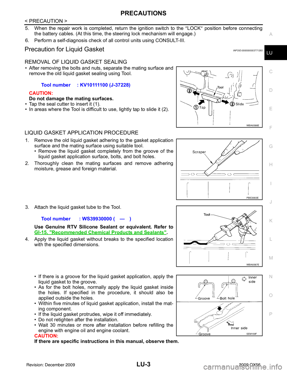
REMOVAL OF LIQUID GASKET SEALING
• After removing the bolts and nuts, separate the mating surface and
remove the old liquid gasket sealing using Tool.
CAUTION:
Do not damage the mating surfaces.
• Tap the seal cutter to insert it (1).
• In areas where the Tool is difficult to use, lightly tap to slide it (2).
LIQUID GASKET APPLICATION PROCEDURE
1. Remove the old liquid gasket adhering to the gasket application surface and the mating surface using suitable tool.
• Remove the liquid gasket completely from the groove of the
liquid gasket application surface, bolts, and bolt holes.
2. Thoroughly clean the mating surfaces and remove adhering moisture, grease and foreign material.
3. Attach the liquid gasket tube to the Tool. Use Genuine RTV Silicone Sealant or equivalent. Refer to
GI-15, "
Recommended Chemical Products and Sealants".
4. Apply the liquid gasket without breaks to the specified location with the specified dimensions.
• If there is a groove for the liquid gasket application, apply theliquid gasket to the groove.
• As for the bolt holes, normally apply the liquid gasket inside
the holes. If specified in the procedure, it should also be
applied outside the holes.
• Within five minutes of liquid gasket application, install the mat-
ing component.
• If the liquid gasket protrudes, wipe it off immediately.
• Do not retighten after the installation.
• Wait 30 minutes or more after installation before refilling the engine with engine oil and engine coolant.
CAUTION:
If there are specific instructions in this manual, observe them.
Tool number : KV10111100 (J-37228)
WBIA0566E
PBIC0003E
Tool number : WS39930000 ( — )
WBIA0567E
SEM159F
Revision: December 20092009 QX56
Page 2669 of 4171
LU-14
< ON-VEHICLE REPAIR >
OIL PUMP
OIL PUMP
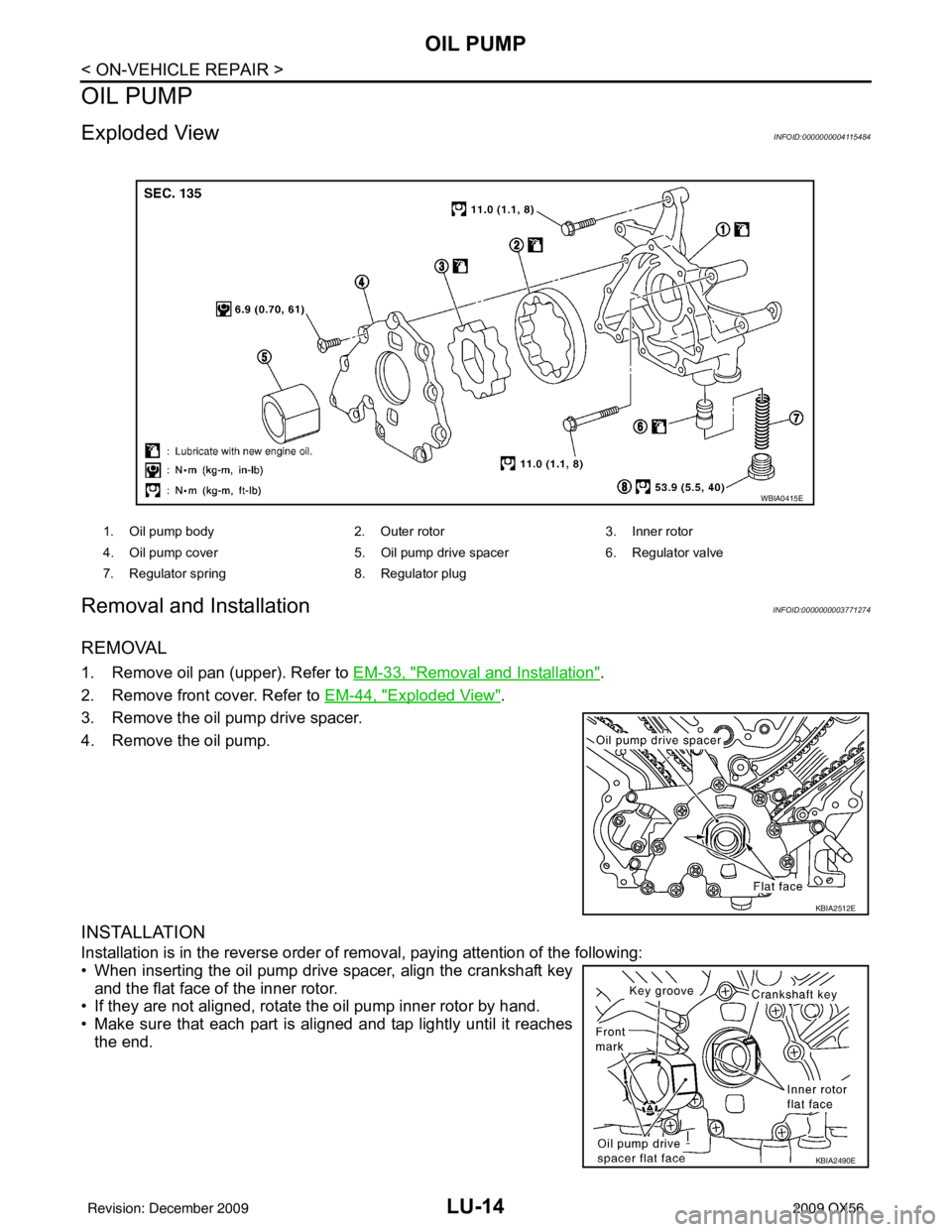
Exploded ViewINFOID:0000000004115484
Removal and InstallationINFOID:0000000003771274
REMOVAL
1. Remove oil pan (upper). Refer to EM-33, "Removal and Installation".
2. Remove front cover. Refer to EM-44, "
Exploded View".
3. Remove the oil pump drive spacer.
4. Remove the oil pump.
INSTALLATION
Installation is in the reverse order of removal, paying attention of the following:
• When inserting the oil pump drive spacer, align the crankshaft key and the flat face of the inner rotor.
• If they are not aligned, rotate the oil pump inner rotor by hand.
• Make sure that each part is aligned and tap lightly until it reaches
the end.
1. Oil pump body 2. Outer rotor 3. Inner rotor
4. Oil pump cover 5. Oil pump drive spacer 6. Regulator valve
7. Regulator spring 8. Regulator plug
WBIA0415E
KBIA2512E
KBIA2490E
Revision: December 20092009 QX56
Page 2689 of 4171
MA-16
< ON-VEHICLE MAINTENANCE >
ENGINE MAINTENANCE
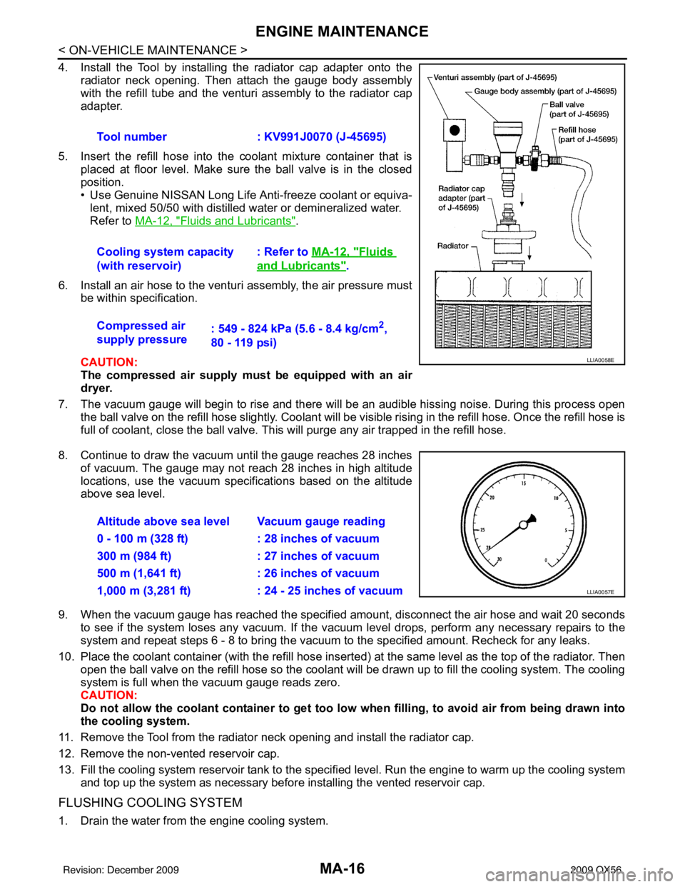
4. Install the Tool by installing the radiator cap adapter onto theradiator neck opening. Then attach the gauge body assembly
with the refill tube and the venturi assembly to the radiator cap
adapter.
5. Insert the refill hose into the coolant mixture container that is placed at floor level. Make sure the ball valve is in the closed
position.
• Use Genuine NISSAN Long Life Anti-freeze coolant or equiva-
lent, mixed 50/50 with distilled water or demineralized water.
Refer to MA-12, "
Fluids and Lubricants".
6. Install an air hose to the venturi assembly, the air pressure must be within specification.
CAUTION:
The compressed air supply must be equipped with an air
dryer.
7. The vacuum gauge will begin to rise and there will be an audible hissing noise. During this process open the ball valve on the refill hose slightly. Coolant will be vi sible rising in the refill hose. Once the refill hose is
full of coolant, close the ball valve. This will purge any air trapped in the refill hose.
8. Continue to draw the vacuum until the gauge reaches 28 inches of vacuum. The gauge may not reach 28 inches in high altitude
locations, use the vacuum specifications based on the altitude
above sea level.
9. When the vacuum gauge has reached the specifi ed amount, disconnect the air hose and wait 20 seconds
to see if the system loses any vacuum. If the vacuum level drops, perform any necessary repairs to the
system and repeat steps 6 - 8 to bring the vacuum to the specified amount. Recheck for any leaks.
10. Place the coolant container (with the refill hose insert ed) at the same level as the top of the radiator. Then
open the ball valve on the refill hose so the coolant will be drawn up to fill the cooling system. The cooling
system is full when the vacuum gauge reads zero.
CAUTION:
Do not allow the coolant container to get too low when filling, to avoid air from being drawn into
the cooling system.
11. Remove the Tool from the radiator neck opening and install the radiator cap.
12. Remove the non-vented reservoir cap.
13. Fill the cooling system reservoir tank to the specif ied level. Run the engine to warm up the cooling system
and top up the system as necessary before installing the vented reservoir cap.
FLUSHING COOLING SYSTEM
1. Drain the water from the engine cooling system. Tool number
: KV991J0070 (J-45695)
Cooling system capacity
(with reservoir) : Refer to
MA-12, "
Fluids
and Lubricants".
Compressed air
supply pressure : 549 - 824 kPa (5.6 - 8.4 kg/cm
2,
80 - 119 psi)
LLIA0058E
Altitude above sea level Vacuum gauge reading
0 - 100 m (328 ft) : 28 inches of vacuum
300 m (984 ft) : 27 inches of vacuum
500 m (1,641 ft) : 26 inches of vacuum
1,000 m (3,281 ft) : 24 - 25 inches of vacuum
LLIA0057E
Revision: December 20092009 QX56
Page 2746 of 4171
MWI-24
< FUNCTION DIAGNOSIS >
DIAGNOSIS SYSTEM (METER)
DIAGNOSIS SYSTEM (METER)
Diagnosis DescriptionINFOID:0000000003776626
SELF-DIAGNOSIS MODE
The following items can be checked during Combination Meter Self-Diagnosis Mode.
• Gauge sweep and present gauge values.
• Illuminates all odometer/trip meters and A/T indicator segments.
• Illuminates all micro controlled lamps/LEDs regardless of switch position.
• Displays estimated present battery voltage.
• Displays seat belt buckle switch LH status.
OPERATION PROCEDURE
NOTE:
• Once entered, combination meter self-diagnosis mode will function with the ignition switch in ON or START.
Combination meter self-diagnosis mode will exit upon turning the ignition switch to OFF or ACC.
• If the diagnosis function is activated with trip A displa yed, the mileage on trip A is reset to 0000.0. (Trip B
operates the same way.)
To initiate combination meter self-diagnosis mode, refer to the following procedure.
1. Turn the ignition switch ON, while pressing the odometer/trip meter switch for 5 - 8 \
seconds. When the diagnosis function is activated, the odometer/trip meter will display tESt.
NOTE:
Check combination meter power supply and ground circuit when self-diagnosis mode of combination meter
does not start. Refer to MWI-30, "
COMBINATION METER : Diagnosis Procedure". Replace combination
meter if normal. Refer to MWI-102, "
Removal and Installation".
COMBINATION METER SELF-DIAGNOSIS MODE FUNCTIONS
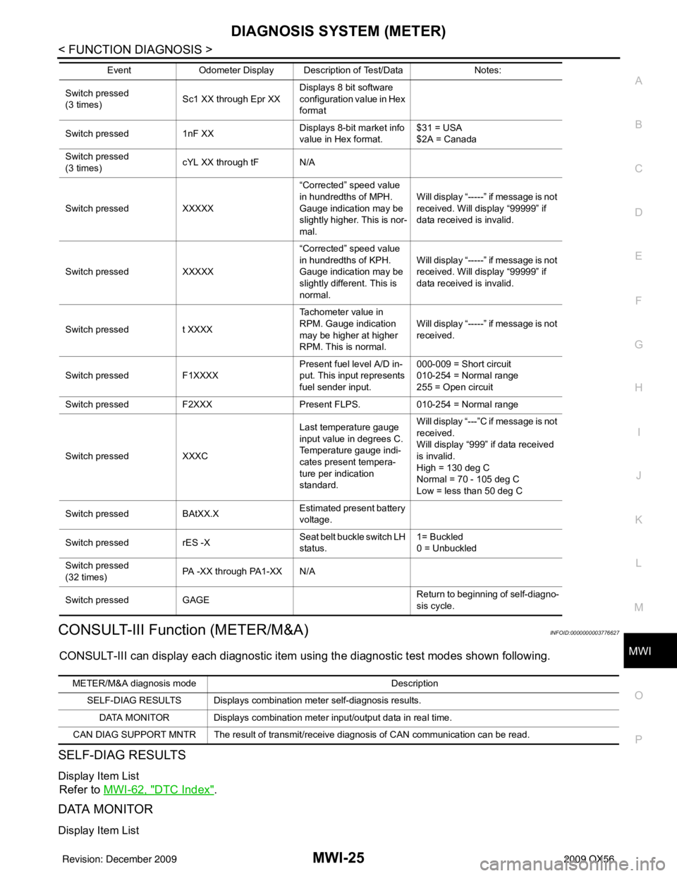
To interpret combination meter self-diagnosis mode functions, refer to the following table.
EventOdometer Display Description of Test/Data Notes:
Odometer/trip meter A/B
switch held from 5 to 8
seconds (or until re-
leased) tESt
Initiating self-diagnosis mode
Switch released GAGE Performs sweep of all
gauges, then displays
present gauge values.Gauges sweep within 10 seconds
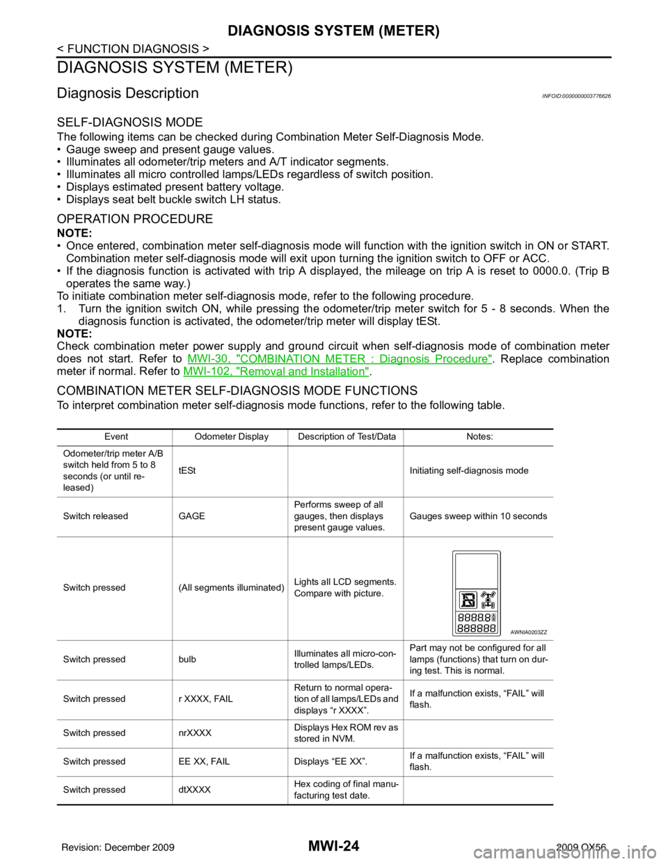
Switch pressed (All segments illuminated) Lights all LCD segments.
Compare with picture.
Switch pressed bulbIlluminates all micro-con-
trolled lamps/LEDs. Part may not be configured for all
lamps (functions) th
at turn on dur-
ing test. This is normal.
Switch pressed r XXXX, FAIL Return to normal opera-
tion of all lamps/LEDs and
displays “r XXXX”.If a malfunction exists, “FAIL” will
flash.
Switch pressed nrXXXX Displays Hex ROM rev as
stored in NVM.
Switch pressed EE XX, FAIL Displays “EE XX”.If a malfunction exists, “FAIL” will
flash.
Switch pressed dtXXXX Hex coding of final manu-
facturing test date.
AWNIA0203ZZ
Revision: December 20092009 QX56
Page 2747 of 4171
MWI
DIAGNOSIS SYSTEM (METER)MWI-25
< FUNCTION DIAGNOSIS >
C
DE
F
G H
I
J
K L
M B A
O P
CONSULT-III Function (METER/M&A)INFOID:0000000003776627
CONSULT-III can display each diagnostic item us ing the diagnostic test modes shown following.
SELF-DIAG RESULTS
Display Item List
Refer to MWI-62, "DTC Index".
DATA MONITOR
Display Item List
Switch pressed
(3 times) Sc1 XX through Epr XXDisplays 8 bit software
configuration value in Hex
format
Switch pressed 1nF XXDisplays 8-bit market info
value in Hex format. $31 = USA
$2A = Canada
Switch pressed
(3 times) cYL XX through tF N/A
Switch pressed XXXXX “Corrected” speed value
in hundredths of MPH.
Gauge indication may be
slightly higher. This is nor-
mal.Will display “-----” if message is not
received. Will display “99999” if
data received is invalid.
Switch pressed XXXXX “Corrected” speed value
in hundredths of KPH.
Gauge indication may be
slightly different. This is
normal.Will display “-----” if message is not
received. Will display “99999” if
data received is invalid.
Switch pressed t XXXX Tachometer value in
RPM. Gauge indication
may be higher at higher
RPM. This is normal.Will display “-----” if message is not
received.
Switch pressed F1XXXX Present fuel level A/D in-
put. This input represents
fuel sender input.000-009 = Short circuit
010-254 = Normal range
255 = Open circuit
Switch pressed F2XXX Present FLPS.010-254 = Normal range
Switch pressed XXXC Last temperature gauge
input value in degrees C.
Temperature gauge indi-
cates present tempera-
ture per indication
standard.Will display “---”C if
message is not
received.
Will display “999” if data received
is invalid.
High = 130 deg C
Normal = 70 - 105 deg C
Low = less than 50 deg C
Switch pressed BAtXX.X Estimated present battery
voltage.
Switch pressed rES -X Seat belt buckle switch LH
status.1= Buckled
0 = Unbuckled
Switch pressed
(32 times) PA -XX through PA1-XX N/A
Switch pressed GAGE Return to beginning of self-diagno-
sis cycle.
Event
Odometer Display Description of Test/Data Notes:
METER/M&A diagnosis mode Description
SELF-DIAG RESULTS Displays combination meter self-diagnosis results. DATA MONITOR Displays combination meter input/output data in real time.
CAN DIAG SUPPORT MNTR The result of transmit/receive diagnosis of CAN communication can be read.
Revision: December 20092009 QX56
Page 2749 of 4171

MWI
DIAGNOSIS SYSTEM (METER)MWI-27
< FUNCTION DIAGNOSIS >
C
DE
F
G H
I
J
K L
M B A
O P
NOTE:
Some items are not available due to vehicle specification.
*: The monitor will indicate “OFF” even though the brake warnin g lamp is on if either of the following conditions exist.
• The parking brake is engaged
• The brake fluid level is low CRUISE W/L [ON/OFF]
X Indicates [ON/OFF] condition of CRUISE warning lamp.
4WD LOCK SW [ON/OFF] X Indicates [ON/OFF] condition of 4WD lock switch.
4WD LOCK IND [ON/OFF] X Indicates [ON/OFF] condition of 4WD lock indicator.
SEAT BELT W/L [ON/OFF] X Indicates [ON/OFF] condition of seat belt warning lamp.
FR FOG IND [ON/OFF] X This item is not used for this model. “OFF” is always displayed.
RR FOG IND [ON/OFF] X This item is not used for this model. “OFF” is always displayed.
LIGHT IND [ON/OFF] X Indicates [ON/OFF] condition of light indicator.
PNP P SW [ON/OFF] XX Indicates [ON/OFF] condition of park/neutral position P switch.
PNP N SW [ON/OFF] XX Indicates [ON/OFF] condition of park/neutral position N switch.
4WD W/L [ON/OFF] X Indicates [ON/OFF] condition of 4WD warning lamp.
Display item [Unit]
MAIN
SIGNALS SELECTION
FROM MENU Description
Revision: December 20092009 QX56