Page 2392 of 4171
![INFINITI QX56 2009 Factory Service Manual AMBIENT SENSORHAC-79
< COMPONENT DIAGNOSIS > [AUTOMATIC AIR CONDITIONER]
C
D
E
F
G H
J
K L
M A
B
HAC
N
O P
AMBIENT SENSOR
Component DescriptionINFOID:0000000003775374
COMPONENT DESCRIPTION
Ambient Sen INFINITI QX56 2009 Factory Service Manual AMBIENT SENSORHAC-79
< COMPONENT DIAGNOSIS > [AUTOMATIC AIR CONDITIONER]
C
D
E
F
G H
J
K L
M A
B
HAC
N
O P
AMBIENT SENSOR
Component DescriptionINFOID:0000000003775374
COMPONENT DESCRIPTION
Ambient Sen](/manual-img/42/57031/w960_57031-2391.png)
AMBIENT SENSORHAC-79
< COMPONENT DIAGNOSIS > [AUTOMATIC AIR CONDITIONER]
C
D
E
F
G H
J
K L
M A
B
HAC
N
O P
AMBIENT SENSOR
Component DescriptionINFOID:0000000003775374
COMPONENT DESCRIPTION
Ambient Sensor
The ambient sensor (1) is attached on the radiator core support (left
side). It detects ambient temperature and converts it into a value
which is then input into the A/C auto amp.
AMBIENT TEMPERATURE INPUT PROCESS
The A/C auto amp. includes a processing circuit for the ambient sensor input. However, when the temperature
detected by the ambient sensor increases quickly, the pr ocessing circuit retards the A/C auto amp. function. It
only allows the A/C auto amp. to recognize an ambient temperature increase of 0.33°C (0.6 °F) per 100 sec-
onds.
This prevents constant adjustments due to momentary conditions, such as stopping after high speed driving.
Although the actual ambient temperature has not changed, the temperature detected by the ambient sensor
will increase. This is because the heat from the engine comp artment can radiate to the front grille area, loca-
tion of the ambient sensor.
Ambient Sensor Diagnosis ProcedureINFOID:0000000003775375
DIAGNOSTIC PROCEDURE FOR AMBIENT SENSOR
SYMPTOM: Ambient sensor circuit is open or shorted. (40 or 41 is
indicated on A/C auto amp. as a result of conducting the A/C auto
amp. self-diagnosis)
1.CHECK VOLTAGE BETWEEN AMBIENT SENSOR AND GROUND
1. Disconnect ambient sensor connector.
2. Turn ignition switch ON.
3. Check voltage between ambient sensor harness connector E1 terminal 1 and ground.
Is the inspection result normal?
YES >> GO TO 2.
NO >> GO TO 4.
2.CHECK CIRCUIT CONTINUITY BETWEEN AM BIENT SENSOR AND A/C AUTO AMP.
AWIIA0238ZZ
AWIIA0160GB
1 - Ground: Approx. 5V
AWIIA0161ZZ
Revision: December 20092009 QX56
Page 2413 of 4171
HAC-100
< ECU DIAGNOSIS >[AUTOMATIC AIR CONDITIONER]
AIR CONDITIONER CONTROL
ABIIA0055GB
Revision: December 20092009 QX56
Page 2426 of 4171
INSUFFICIENT COOLINGHAC-113
< SYMPTOM DIAGNOSIS > [AUTOMATIC AIR CONDITIONER]
C
D
E
F
G H
J
K L
M A
B
HAC
N
O P
Performance ChartINFOID:0000000003775393
Test Condition
Testing must be performed as follows:
*1 VTL-12, "Removal and Installation"*2HAC-51, "Front Blower Motor Com-
ponent Function Check"
*3 HA-32, "Removal and Installation for
Compressor Clutch"
*4EM-13, "Checking Drive Belts"*5HA-31, "Removal and Installation for
Compressor"
AWIIA1000GB
Revision: December 20092009 QX56
Page 2433 of 4171
HAC-120
< SYMPTOM DIAGNOSIS >[AUTOMATIC AIR CONDITIONER]
NOISE
NOISE
Component Function CheckINFOID:0000000003775397
SYMPTOM: Noise
INSPECTION FLOW
AWIIA1001GB
Revision: December 20092009 QX56
Page 2451 of 4171

INTERIOR ROOM LAMP CONTROL SYSTEMINL-7
< FUNCTION DIAGNOSIS >
C
DE
F
G H
I
J
K
M A
B
INL
N
O P
INTERIOR LAMP BATTERY SAVER CONTROL
If an interior lamp is left ON and does not turn OFF even when the doors are closed, the BCM turns off power
to the interior lamps automatically to save the batte ry 30 minutes after the ignition switch is turned OFF.
The BCM controls power and ground to all interior lamps.
After the battery saver system turns the la mps OFF, the lamps will illuminate again when
• a signal is received from an Intelligent Key or main power window and door lock/unlock switch, or when the
front door LH lock assembly (key cylinder switch) is locked or unlocked
• a door is opened or closed
• the Intelligent Key is removed from or inserted into the ignition switch.
The Interior lamp battery saver control time peri od can be changed with the function setting of CONSULT-III.
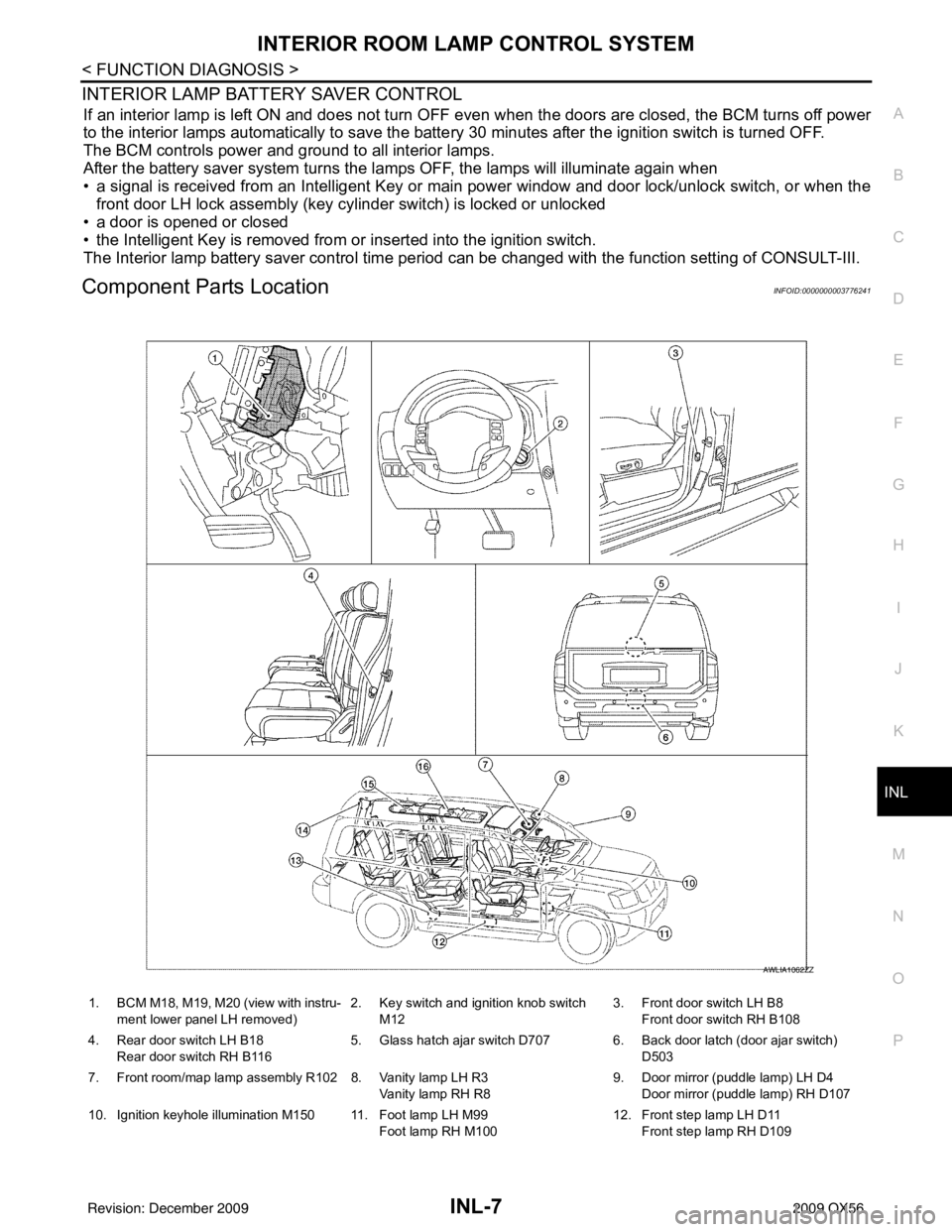
Component Parts LocationINFOID:0000000003776241
1. BCM M18, M19, M20 (view with instru-
ment lower panel LH removed) 2. Key switch and ignition knob switch
M12 3. Front door switch LH B8
Front door switch RH B108
4. Rear door switch LH B18 Rear door switch RH B116 5. Glass hatch ajar switch D707 6. Back door latch (door ajar switch)
D503
7. Front room/map lamp assembly R102 8. Vanity lamp LH R3 Vanity lamp RH R89. Door mirror (puddle lamp) LH D4
Door mirror (puddle lamp) RH D107
10. Ignition keyhole illumination M150 11. Foot lamp LH M99 Foot lamp RH M10012. Front step lamp LH D11
Front step lamp RH D109
AWLIA1062ZZ
Revision: December 20092009 QX56
Page 2460 of 4171

INL-16
< COMPONENT DIAGNOSIS >
BATTERY SAVER OUTPUT/POWER SUPPLY CIRCUIT
- Front step lamp LH
- Front step lamp RH
- Door mirror LH
- Door mirror RH
- Rear step lamp LH
- Rear step lamp RH
- Foot lamp LH
- Foot lamp RH
- Front room/map lamp assembly
- Vanity lamp LH
- Vanity lamp RH
- Cargo lamp
- Personal lamp 2nd row
- Personal lamp 3rd row
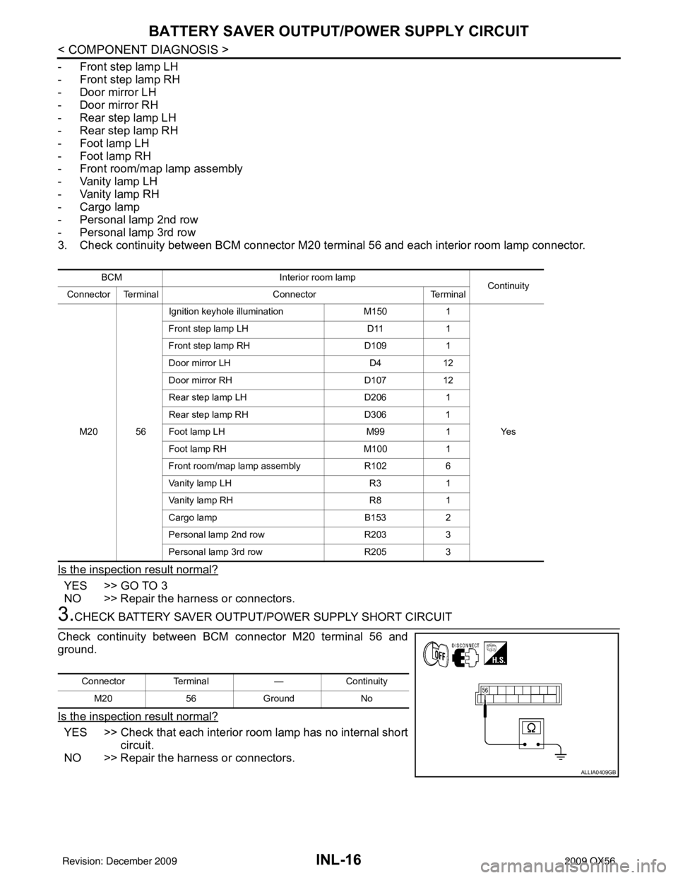
3. Check continuity between BCM connector M20 terminal 56 and each interior room lamp connector.
Is the inspection result normal?
YES >> GO TO 3
NO >> Repair the harness or connectors.
3.CHECK BATTERY SAVER OUTPUT/P OWER SUPPLY SHORT CIRCUIT
Check continuity between BCM connector M20 terminal 56 and
ground.
Is the inspection result normal?
YES >> Check that each interior room lamp has no internal short circuit.
NO >> Repair the harness or connectors.
BCM Interior room lamp
Continuity
Connector Terminal ConnectorTerminal
M20 56 Ignition keyhole illumination
M1501
Ye s
Front step lamp LH
D111
Front step lamp RH D1091
Door mirror LH D412
Door mirror RH D10712
Rear step lamp LH D2061
Rear step lamp RH D3061
Foot lamp LH M991
Foot lamp RH M1001
Front room/map lamp assembly R1026
Vanity lamp LH R31
Vanity lamp RH R81
Cargo lamp B1532
Personal lamp 2nd row R2033
Personal lamp 3rd row R2053
Connector Terminal —Continuity
M20 56Ground No
ALLIA0409GB
Revision: December 20092009 QX56
Page 2464 of 4171

INL-20
< COMPONENT DIAGNOSIS >
STEP LAMP CIRCUIT
1. Turn ignition switch OFF.
2. Disconnect BCM connector M20, front step lamp, rear step lampand foot lamp connectors.
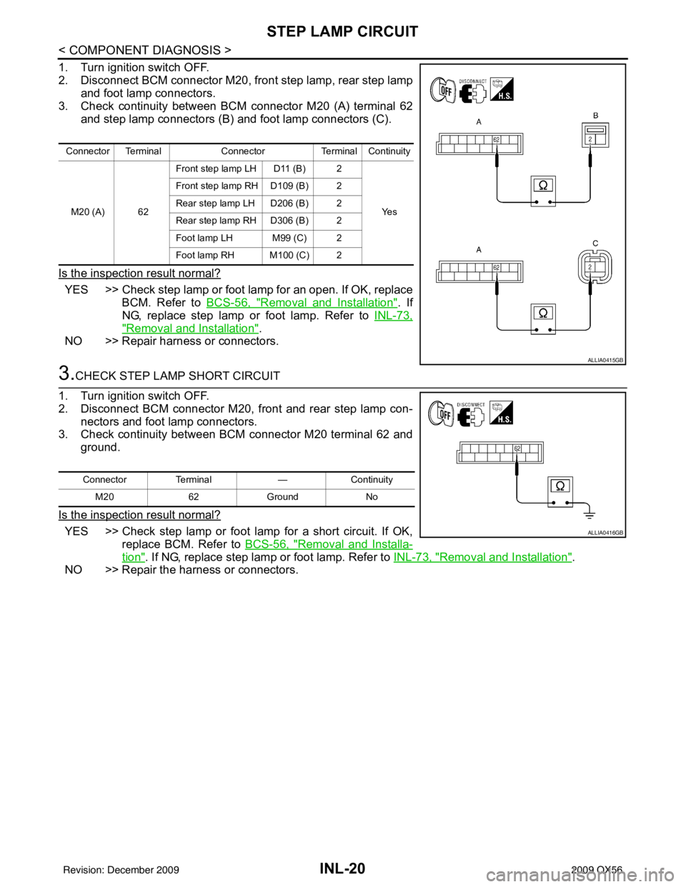
3. Check continuity between BCM connector M20 (A) terminal 62 and step lamp connectors (B) and foot lamp connectors (C).
Is the inspection result normal?
YES >> Check step lamp or foot lamp for an open. If OK, replace BCM. Refer to BCS-56, "
Removal and Installation". If
NG, replace step lamp or foot lamp. Refer to INL-73,
"Removal and Installation".
NO >> Repair harness or connectors.
3.CHECK STEP LAMP SHORT CIRCUIT
1. Turn ignition switch OFF.
2. Disconnect BCM connector M20, front and rear step lamp con- nectors and foot lamp connectors.
3. Check continuity between BCM connector M20 terminal 62 and ground.
Is the inspection result normal?
YES >> Check step lamp or foot lamp for a short circuit. If OK, replace BCM. Refer to BCS-56, "
Removal and Installa-
tion". If NG, replace step lamp or foot lamp. Refer to INL-73, "Removal and Installation".
NO >> Repair the harness or connectors.
Connector Terminal ConnectorTerminal Continuity
M20 (A) 62 Front step lamp LH D11 (B) 2
Ye s
Front step lamp RH D109 (B) 2
Rear step lamp LH D206 (B) 2
Rear step lamp
RH D306 (B) 2
Foot lamp LH M99 (C) 2
Foot lamp RH M100 (C) 2
ALLIA0415GB
Connector Terminal —Continuity
M20 62Ground No
ALLIA0416GB
Revision: December 20092009 QX56
Page 2512 of 4171

INL-68
< ECU DIAGNOSIS >
BCM (BODY CONTROL MODULE)
DTC Inspection Priority Chart
INFOID:0000000004109556
If some DTCs are displayed at the same time, perform inspections one by one based on the following priority
chart.
DTC IndexINFOID:0000000004109557
NOTE: Details of time display
• CRNT: Displays when there is a malfunction now or after returning to the normal condition until turning igni-
tion switch OFF → ON again.
• 1 - 39: Displayed if any previous malfunction is present when current condition is normal. It increases like 1
→ 2 → 3...38 → 39 after returning to the normal condition whenever ignition switch OFF → ON. The counter
remains at 39 even if the number of cycles exceeds it. It is counted from 1 again when turning ignition switch
OFF → ON after returning to the normal condition if the malfunction is detected again.
Display contents of CONS ULTFail-safe Cancellation
U1000: CAN COMM CIRCUIT I nhibit engine crankingWhen the BCM re-establishes communication with the other mod-
ules.
U1010: CONTROL UNIT (CAN) Inhibit engine cranking When the BCM re-start communicating with the other modules.
Priority DTC
1 • U1000: CAN COMM CIRCUIT
• U1010: CONTROL UNIT (CAN)
2 • B2190: NATS ANTENNA AMP
• B2191: DIFFERENCE OF KEY
• B2192: ID DISCORD BCM-ECM
• B2193: CHAIN OF BCM-ECM
• B2013: STRG COMM 1
• B2552: INTELLIGENT KEY
• B2590: NATS MALFUNCTION
3 • C1729: VHCL SPEED SIG ERR
• C1735: IGNITION SIGNAL
4 • C1704: LOW PRESSURE FL
• C1705: LOW PRESSURE FR
• C1706: LOW PRESSURE RR
• C1707: LOW PRESSURE RL
• C1708: [NO DATA] FL
• C1709: [NO DATA] FR
• C1710: [NO DATA] RR
• C1711: [NO DATA] RL
• C1712: [CHECKSUM ERR] FL
• C1713: [CHECKSUM ERR] FR
• C1714: [CHECKSUM ERR] RR
• C1715: [CHECKSUM ERR] RL
• C1716: [PRESSDATA ERR] FL
• C1717: [PRESSDATA ERR] FR
• C1718: [PRESSDATA ERR] RR
• C1719: [PRESSDATA ERR] RL
• C1720: [CODE ERR] FL
• C1721: [CODE ERR] FR
• C1722: [CODE ERR] RR
• C1723: [CODE ERR] RL
• C1724: [BATT VOLT LOW] FL
• C1725: [BATT VOLT LOW] FR
• C1726: [BATT VOLT LOW] RR
• C1727: [BATT VOLT LOW] RL
Revision: December 20092009 QX56