2009 INFINITI QX56 100
[x] Cancel search: 100Page 2603 of 4171
![INFINITI QX56 2009 Factory Service Manual LAN-34
< BASIC INSPECTION >[CAN FUNDAMENTAL]
DIAGNOSIS AND REPAIR WORKFLOW
7. Perform the inspection procedure for the possi
ble cause. Refer to “MALFUNCTION AREA CHART”.
Past Error — Short Circ INFINITI QX56 2009 Factory Service Manual LAN-34
< BASIC INSPECTION >[CAN FUNDAMENTAL]
DIAGNOSIS AND REPAIR WORKFLOW
7. Perform the inspection procedure for the possi
ble cause. Refer to “MALFUNCTION AREA CHART”.
Past Error — Short Circ](/manual-img/42/57031/w960_57031-2602.png)
LAN-34
< BASIC INSPECTION >[CAN FUNDAMENTAL]
DIAGNOSIS AND REPAIR WORKFLOW
7. Perform the inspection procedure for the possi
ble cause. Refer to “MALFUNCTION AREA CHART”.
Past Error — Short Circuit —
When the symptoms listed below exist, a short circuit of the CAN communication line is a possible cause.
PKID1224E
Item (CONSULT-III) IndicationInspection procedure
SELF-DIAG RESULTS “U1000” and “U1001” is indicated in the past for most units. Refer to “MALFUNCTION AREA
CHART”.
CAN DIAG SUPPORT MNTR Only on CAN DIAG SUPPORT MNTR (with PAST), “1 - 39” is in-
dicated on “PAST” of “TRANSMIT DIAG” and the reception item.
Revision: December 20092009 QX56
Page 2620 of 4171
![INFINITI QX56 2009 Factory Service Manual LAN
TROUBLE DIAGNOSISLAN-51
< FUNCTION DIAGNOSIS > [CAN]
C
D
E
F
G H
I
J
K L
B A
O P
N
Never replace the unit even when “NG” is indicated on the “INITIAL DIAG” at this stage. Fo
llow the troub INFINITI QX56 2009 Factory Service Manual LAN
TROUBLE DIAGNOSISLAN-51
< FUNCTION DIAGNOSIS > [CAN]
C
D
E
F
G H
I
J
K L
B A
O P
N
Never replace the unit even when “NG” is indicated on the “INITIAL DIAG” at this stage. Fo
llow the troub](/manual-img/42/57031/w960_57031-2619.png)
LAN
TROUBLE DIAGNOSISLAN-51
< FUNCTION DIAGNOSIS > [CAN]
C
D
E
F
G H
I
J
K L
B A
O P
N
Never replace the unit even when “NG” is indicated on the “INITIAL DIAG” at this stage. Fo
llow the trouble diagnosis proce-
dures.
IPDM E/R
0: Error at present, 1 – 39: Error in the past (Number means the number of times the ignition switch is turned OFF→ ON)
*: 39 or higher number is fixed at 39 until the self-diagnosis result is erased.
DTC IndexINFOID:0000000003776456
ITEMCAN DIAG SUP-
PORT MNTR Description Normal
Error
PRSNT PAST PRSNT PAST
IPDM-E TRANSMIT DIAG Signal transmission status
OKOK
or
1 – 39
*UNKWN 0
ECM Signal receiving status from the ECM
BCM/SEC Signal receiving status from the BCM
DTC Self-diagnosis item
(CONSULT-III indication) DTC detection condition
Inspection
U1000 CAN COMM CIRCUIT When ECM is not transmitting or receiving CAN com-
munication signal of OBD (emission-related diagnosis)
for 2 seconds or more.
Refer to LAN-36
.
When a control unit (except for ECM) is not transmitting
or receiving CAN communication signal for 2 seconds
or more.
U1001 CAN COMM CIRCUIT When ECM is not transmitting or receiving CAN com-
munication signal other than OBD (emission-related di-
agnosis) for 2 seconds or more.
U1002 SYSTEM COMM When a control unit is not transmitting or receiving CAN
communication signal for 2 seconds or less. Start the inspection. Refer
to the applicable section
of the indicated control
unit.
U1010 CONTROL UNIT(CAN) When an error is detected during the initial diagnosis for
CAN controller of each control unit. Replace the control unit
indicating “U1010”.
Revision: December 20092009 QX56
Page 2658 of 4171
PRECAUTIONSLU-3
< PRECAUTION >
C
DE
F
G H
I
J
K L
M A
LU
NP
O
5. When the repair work is completed, return the ignition switch to the
″LOCK ″ position before connecting
the battery cables. (At this time, the steering lock mechanism will engage.)
6. Perform a self-diagnosis check of al l control units using CONSULT-III.
Precaution for Liquid GasketINFOID:0000000003771265
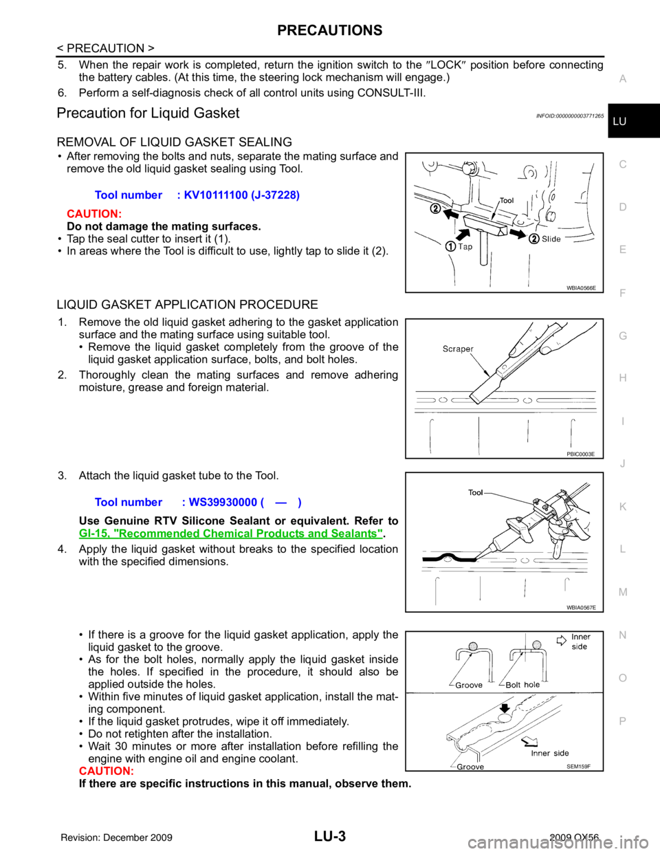
REMOVAL OF LIQUID GASKET SEALING
• After removing the bolts and nuts, separate the mating surface and
remove the old liquid gasket sealing using Tool.
CAUTION:
Do not damage the mating surfaces.
• Tap the seal cutter to insert it (1).
• In areas where the Tool is difficult to use, lightly tap to slide it (2).
LIQUID GASKET APPLICATION PROCEDURE
1. Remove the old liquid gasket adhering to the gasket application surface and the mating surface using suitable tool.
• Remove the liquid gasket completely from the groove of the
liquid gasket application surface, bolts, and bolt holes.
2. Thoroughly clean the mating surfaces and remove adhering moisture, grease and foreign material.
3. Attach the liquid gasket tube to the Tool. Use Genuine RTV Silicone Sealant or equivalent. Refer to
GI-15, "
Recommended Chemical Products and Sealants".
4. Apply the liquid gasket without breaks to the specified location with the specified dimensions.
• If there is a groove for the liquid gasket application, apply theliquid gasket to the groove.
• As for the bolt holes, normally apply the liquid gasket inside
the holes. If specified in the procedure, it should also be
applied outside the holes.
• Within five minutes of liquid gasket application, install the mat-
ing component.
• If the liquid gasket protrudes, wipe it off immediately.
• Do not retighten after the installation.
• Wait 30 minutes or more after installation before refilling the engine with engine oil and engine coolant.
CAUTION:
If there are specific instructions in this manual, observe them.
Tool number : KV10111100 (J-37228)
WBIA0566E
PBIC0003E
Tool number : WS39930000 ( — )
WBIA0567E
SEM159F
Revision: December 20092009 QX56
Page 2659 of 4171
LU-4
< PREPARATION >
PREPARATION
PREPARATION
PREPARATION
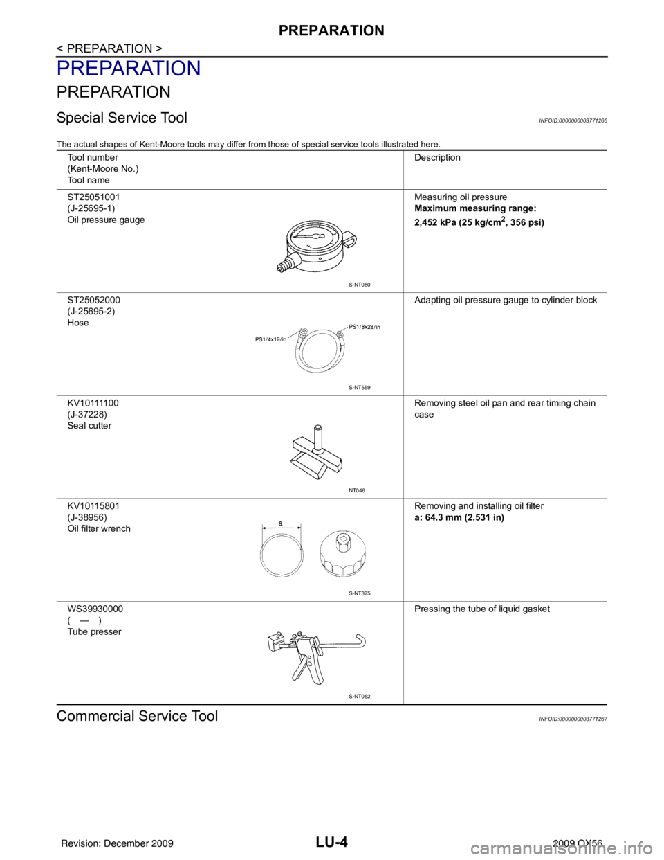
Special Service ToolINFOID:0000000003771266
The actual shapes of Kent-Moore tools may differ from those of special service tools illustrated here.
Commercial Service ToolINFOID:0000000003771267
Tool number
(Kent-Moore No.)
Tool name Description
ST25051001
(J-25695-1)
Oil pressure gauge Measuring oil pressure
Maximum measuring range:
2,452 kPa (25 kg/cm
2, 356 psi)
ST25052000
(J-25695-2)
Hose Adapting oil pressure gauge to cylinder block
K V 1 0 1111 0 0
(J-37228)
Seal cutter Removing steel oil pan and rear timing chain
case
KV10115801
(J-38956)
Oil filter wrench Removing and installing oil filter
a: 64.3 mm (2.531 in)
WS39930000
(—)
Tube presser Pressing the tube of liquid gasket
S-NT050
S-NT559
NT046
S-NT375
S-NT052
Revision: December 20092009 QX56
Page 2664 of 4171
ENGINE OILLU-9
< ON-VEHICLE MAINTENANCE >
C
DE
F
G H
I
J
K L
M A
LU
NP
O
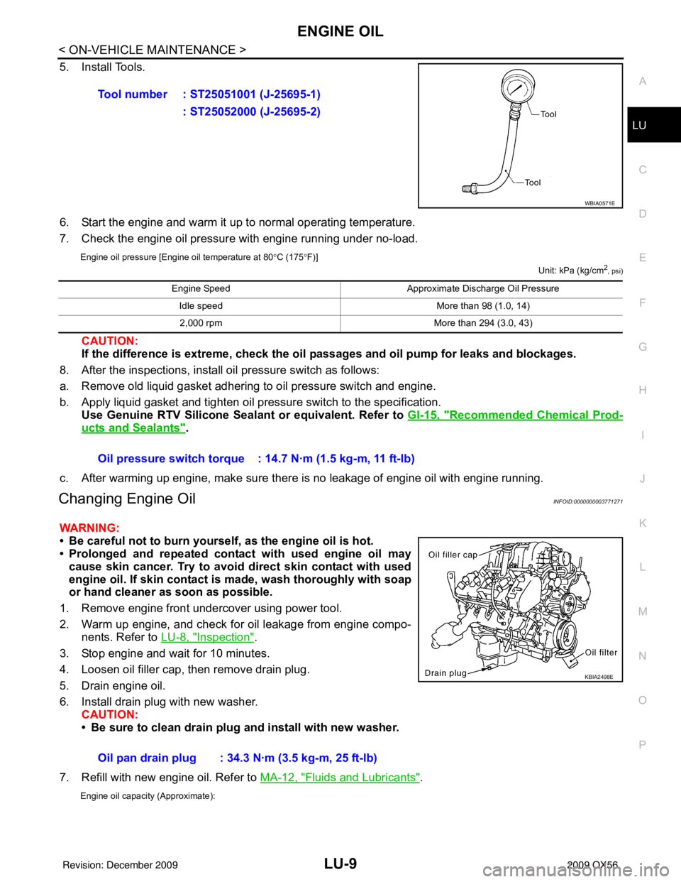
5. Install Tools.
6. Start the engine and warm it up to normal operating temperature.
7. Check the engine oil pressure with engine running under no-load.
Engine oil pressure [Engine oil temperature at 80
°C (175 °F)]
Unit: kPa (kg/cm2, psi)
CAUTION:
If the difference is extreme, check the oil passages and oil pump for leaks and blockages.
8. After the inspections, install oil pressure switch as follows:
a. Remove old liquid gasket adhering to oil pressure switch and engine.
b. Apply liquid gasket and tighten oil pressure switch to the specification. Use Genuine RTV Silicone Seal ant or equivalent. Refer to GI-15, "
Recommended Chemical Prod-
ucts and Sealants".
c. After warming up engine, make sure there is no leakage of engine oil with engine running.
Changing Engine OilINFOID:0000000003771271
WARNING:
• Be careful not to burn yourself, as the engine oil is hot.
• Prolonged and repeated contact with used engine oil may cause skin cancer. Try to avoid direct skin contact with used
engine oil. If skin contact is made, wash thoroughly with soap
or hand cleaner as soon as possible.
1. Remove engine front undercover using power tool.
2. Warm up engine, and check for oil leakage from engine compo- nents. Refer to LU-8, "
Inspection".
3. Stop engine and wait for 10 minutes.
4. Loosen oil filler cap, then remove drain plug.
5. Drain engine oil.
6. Install drain plug with new washer. CAUTION:
• Be sure to clean drain plug and install with new washer.
7. Refill with new engine oil. Refer to MA-12, "
Fluids and Lubricants".
Engine oil capacity (Approximate):
Tool number : ST25051001 (J-25695-1)
: ST25052000 (J-25695-2)
WBIA0571E
Engine Speed Approximate Discharge Oil Pressure
Idle speed More than 98 (1.0, 14)
2,000 rpm More than 294 (3.0, 43)
Oil pressure switch torque : 14.7 N·m (1.5 kg-m, 11 ft-lb)
Oil pan drain plug : 34.3 N·m (3.5 kg-m, 25 ft-lb)
KBIA2498E
Revision: December 20092009 QX56
Page 2689 of 4171
MA-16
< ON-VEHICLE MAINTENANCE >
ENGINE MAINTENANCE
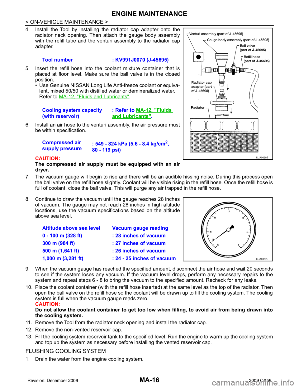
4. Install the Tool by installing the radiator cap adapter onto theradiator neck opening. Then attach the gauge body assembly
with the refill tube and the venturi assembly to the radiator cap
adapter.
5. Insert the refill hose into the coolant mixture container that is placed at floor level. Make sure the ball valve is in the closed
position.
• Use Genuine NISSAN Long Life Anti-freeze coolant or equiva-
lent, mixed 50/50 with distilled water or demineralized water.
Refer to MA-12, "
Fluids and Lubricants".
6. Install an air hose to the venturi assembly, the air pressure must be within specification.
CAUTION:
The compressed air supply must be equipped with an air
dryer.
7. The vacuum gauge will begin to rise and there will be an audible hissing noise. During this process open the ball valve on the refill hose slightly. Coolant will be vi sible rising in the refill hose. Once the refill hose is
full of coolant, close the ball valve. This will purge any air trapped in the refill hose.
8. Continue to draw the vacuum until the gauge reaches 28 inches of vacuum. The gauge may not reach 28 inches in high altitude
locations, use the vacuum specifications based on the altitude
above sea level.
9. When the vacuum gauge has reached the specifi ed amount, disconnect the air hose and wait 20 seconds
to see if the system loses any vacuum. If the vacuum level drops, perform any necessary repairs to the
system and repeat steps 6 - 8 to bring the vacuum to the specified amount. Recheck for any leaks.
10. Place the coolant container (with the refill hose insert ed) at the same level as the top of the radiator. Then
open the ball valve on the refill hose so the coolant will be drawn up to fill the cooling system. The cooling
system is full when the vacuum gauge reads zero.
CAUTION:
Do not allow the coolant container to get too low when filling, to avoid air from being drawn into
the cooling system.
11. Remove the Tool from the radiator neck opening and install the radiator cap.
12. Remove the non-vented reservoir cap.
13. Fill the cooling system reservoir tank to the specif ied level. Run the engine to warm up the cooling system
and top up the system as necessary before installing the vented reservoir cap.
FLUSHING COOLING SYSTEM
1. Drain the water from the engine cooling system. Tool number
: KV991J0070 (J-45695)
Cooling system capacity
(with reservoir) : Refer to
MA-12, "
Fluids
and Lubricants".
Compressed air
supply pressure : 549 - 824 kPa (5.6 - 8.4 kg/cm
2,
80 - 119 psi)
LLIA0058E
Altitude above sea level Vacuum gauge reading
0 - 100 m (328 ft) : 28 inches of vacuum
300 m (984 ft) : 27 inches of vacuum
500 m (1,641 ft) : 26 inches of vacuum
1,000 m (3,281 ft) : 24 - 25 inches of vacuum
LLIA0057E
Revision: December 20092009 QX56
Page 2724 of 4171

MWI-2
INFORMATION DISPLAY .........................................19
INFORMATION DISPLAY : System Diagram .........20
INFORMATION DISPLAY : System Description ....20
INFORMATION DISPLAY : Component Parts Lo-
cation ................................................................... ...
21
INFORMATION DISPLAY : Component Descrip-
tion ....................................................................... ...
21
COMPASS .........................................................22
Description (Early Production) ............................. ...22
DIAGNOSIS SYSTEM (METER) .......................24
Diagnosis Description .......................................... ...24
CONSULT-III Function (METER/M&A) ................ ...25
COMPONENT DIAGNOSIS ........................28
DTC U1000 CAN COMMUNICATION ............ ...28
DTC Logic ............................................................ ...28
Diagnosis Procedure .............................................28
DTC B2205 VEHICLE SPEED CIRCUIT ...........29
Description ........................................................... ...29
DTC Logic ...............................................................29
Diagnosis Procedure .............................................29
POWER SUPPLY AND GROUND CIRCUIT .....30
COMBINATION METER ........................................ ...30
COMBINATION METER : Diagnosis Procedure ....30
BCM (BODY CONTROL MODULE) ...................... ...30
BCM (BODY CONTROL MODULE) : Diagnosis
Procedure ...............................................................
31
IPDM E/R (INTELLIGENT POWER DISTRIBU-
TION MODULE ENGINE ROOM) .......................... ...
31
IPDM E/R (INTELLIGENT POWER DISTRIBU-
TION MODULE ENGINE ROOM) : Diagnosis Pro-
cedure .....................................................................
31
FUEL LEVEL SENSOR SIGNAL CIRCUIT .......33
Description ........................................................... ...33
Component Function Check ...................................33
Diagnosis Procedure .............................................33
Component Inspection ............................................34
OIL PRESSURE SWITCH SIGNAL CIRCUIT ...35
Description ..............................................................35
Component Function Check ...................................35
Diagnosis Procedure ..............................................35
Component Inspection ............................................35
PARKING BRAKE SWITCH SIGNAL CIR-
CUIT ...................................................................
36
Description ........................................................... ...36
Component Function Check ...................................36
Diagnosis Procedure ..............................................36
Component Inspection ............................................36
WASHER LEVEL SWITCH SIGNAL CIRCUIT ...37
Description ........................................................... ...37
Diagnosis Procedure ............................................ ...37
Component Inspection ............................................37
COMPASS .........................................................38
Wiring Diagram (Early Production) ...................... ...38
CLOCK ..............................................................40
Wiring Diagram .................................................... ...40
ECU DIAGNOSIS .......................................42
COMBINATION METER ................................. ...42
Reference Value .................................................. ...42
Wiring Diagram .......................................................44
Fail Safe ..................................................................61
DTC Index ...............................................................62
BCM (BODY CONTROL MODULE) ..................64
Reference Value .................................................. ...64
Terminal Layout ......................................................66
Physical Values .......................................................66
Wiring Diagram .......................................................72
Fail Safe .................................................................76
DTC Inspection Priority Chart ...............................77
DTC Index ..............................................................77
IPDM E/R (INTELLIGENT POWER DISTRI-
BUTION MODULE ENGINE ROOM) .................
79
Reference Value .................................................. ...79
Terminal Layout ......................................................81
Physical Values .......................................................81
Wiring Diagram .......................................................86
Fail Safe .................................................................89
DTC Index ..............................................................91
SYMPTOM DIAGNOSIS ............................92
THE FUEL GAUGE POINTER DOES NOT
MOVE .............................................................. ...
92
Description ........................................................... ...92
Diagnosis Procedure ...............................................92
THE FUEL GAUGE POINTER DOES NOT
MOVE TO "F" WHEN REFUELING ..................
93
Description ........................................................... ...93
Diagnosis Procedure ...............................................93
THE OIL PRESSURE WARNING LAMP
DOES NOT TURN ON .................................... ...
94
Description ........................................................... ...94
Diagnosis Procedure ...............................................94
THE OIL PRESSURE WARNING LAMP
DOES NOT TURN OFF .................................. ...
95
Description ........................................................... ...95
Diagnosis Procedure ...............................................95
THE PARKING BRAKE RELEASE WARNING
CONTINUES DISPLAYING, OR DOES NOT
DISPLAY ............................................................
96
Description ........................................................... ...96
Revision: December 20092009 QX56
Page 2725 of 4171
MWI
MWI-3
C
DE
F
G H
I
J
K L
M B
A
O P
Diagnosis Procedure ...........................................
....
96
THE LOW WASHER FLUID WARNING CON-
TINUES DISPLAYING, or DOES NOT DIS-
PLAY ..................................................................
97
Description .......................................................... ....97
Diagnosis Procedure ...............................................97
THE DOOR OPEN WARNING CONTINUES
DISPLAYING, OR DOES NOT DISPLAY ..........
98
Description .......................................................... ....98
Diagnosis Procedure ...............................................98
NORMAL OPERATING CONDITION .................99
COMPASS ............................................................. ....99
COMPASS : Description (Early Production) ...........99
PRECAUTION ............................................100
PRECAUTIONS ...............................................100
Precaution for Supplemental Restraint System
(SRS) "AIR BAG" and "SEAT BELT PRE-TEN-
SIONER" ............................................................. ..
100
Precaution Necessary for Steering Wheel Rota-
tion After Battery Disconnect .................................
100
ON-VEHICLE REPAIR ...............................102
COMBINATION METER .................................102
Removal and Installation ..................................... ..102
CLOCK ............................................................103
Removal and Installation .......................................103
Revision: December 20092009 QX56