2009 INFINITI QX56 100
[x] Cancel search: 100Page 2854 of 4171
![INFINITI QX56 2009 Factory Service Manual PCS
U1000 CAN COMM CIRCUITPCS-17
< COMPONENT DIAGNOSIS > [IPDM E/R]
C
D
E
F
G H
I
J
K L
B A
O P
N
COMPONENT DIAGNOSIS
U1000 CAN COMM CIRCUIT
DescriptionINFOID:0000000003776498
Refer to
LAN-4, "System INFINITI QX56 2009 Factory Service Manual PCS
U1000 CAN COMM CIRCUITPCS-17
< COMPONENT DIAGNOSIS > [IPDM E/R]
C
D
E
F
G H
I
J
K L
B A
O P
N
COMPONENT DIAGNOSIS
U1000 CAN COMM CIRCUIT
DescriptionINFOID:0000000003776498
Refer to
LAN-4, "System](/manual-img/42/57031/w960_57031-2853.png)
PCS
U1000 CAN COMM CIRCUITPCS-17
< COMPONENT DIAGNOSIS > [IPDM E/R]
C
D
E
F
G H
I
J
K L
B A
O P
N
COMPONENT DIAGNOSIS
U1000 CAN COMM CIRCUIT
DescriptionINFOID:0000000003776498
Refer to
LAN-4, "System Description".
DTC LogicINFOID:0000000003776499
DTC DETECTION LOGIC
DTC CONFIRMATION PROCEDURE
Diagnosis ProcedureINFOID:0000000003776500
1. PERFORM SELF DIAGNOSTIC
1. Turn ignition switch ON and wait for 2 seconds or more.
2. Check “SELF-DIAG RESULTS” of IPDM E/R.
Is
“CAN COMM CIRCUIT” displayed?
YES >> Refer to LAN-5, "CAN Communication Control Circuit".
NO >> Refer to GI-38, "
Intermittent Incident".
DTCCONSULT-III display
description DTC Detection Condit
ion Possible cause
U1000 CAN COMM CIRCUIT When IPDM E/R cannot communicate CAN
communication signal continuously for 2
seconds or more In CAN communication system, any item (or items)
of the following listed below is malfunctioning.
• Receiving (TCM)
• Receiving (ECM)
• Receiving (BCM)
• Receiving (Combination meter)
Revision: December 20092009 QX56
Page 2856 of 4171
![INFINITI QX56 2009 Factory Service Manual PCS
IPDM E/R (INTELLIGENT POWER DISTRIBUTION MODULE ENGINE ROOM)
PCS-19
< ECU DIAGNOSIS > [IPDM E/R]
C
D
E
F
G H
I
J
K L
B A
O P
N
ECU DIAGNOSIS
IPDM E/R (INTELLIGENT POWER
DISTRIBUTION MODULE ENGINE INFINITI QX56 2009 Factory Service Manual PCS
IPDM E/R (INTELLIGENT POWER DISTRIBUTION MODULE ENGINE ROOM)
PCS-19
< ECU DIAGNOSIS > [IPDM E/R]
C
D
E
F
G H
I
J
K L
B A
O P
N
ECU DIAGNOSIS
IPDM E/R (INTELLIGENT POWER
DISTRIBUTION MODULE ENGINE](/manual-img/42/57031/w960_57031-2855.png)
PCS
IPDM E/R (INTELLIGENT POWER DISTRIBUTION MODULE ENGINE ROOM)
PCS-19
< ECU DIAGNOSIS > [IPDM E/R]
C
D
E
F
G H
I
J
K L
B A
O P
N
ECU DIAGNOSIS
IPDM E/R (INTELLIGENT POWER
DISTRIBUTION MODULE ENGINE
ROOM)
Reference ValueINFOID:0000000003776502
VALUES ON THE DIAGNOSIS TOOL
Monitor Item ConditionValue/Status
MOTOR FAN REQ Engine idle speed Changes depending on engine
coolant temperature, air conditioner
operation status, vehicle speed,
etc.0 - 100 %
A/C COMP REQ A/C switch OFF
OFF
A/C switch ON ON
TA I L & C L R R E Q Lighting switch OFF
OFF
Lighting switch 1ST, 2ND, HI or AUTO (Light is illuminated) ON
HL LO REQ Lighting switch OFF
OFF
Lighting switch 2ND HI or AUTO (Light is illuminated) ON
HL HI REQ Lighting switch OFF
OFF
Lighting switch HI ON
FR FOG REQ Lighting switch 2ND or AUTO (Light
is illuminated) Front fog lamp switch OFF OFF
• Front fog lamp switch ON
• Daytime light activated (Canada
only) ON
FR WIP REQ Ignition switch ON Front wiper switch OFF
STOP
Front wiper switch INT 1LOW
Front wiper switch LO LOW
Front wiper switch HI HI
WIP AUTO STOP Ignition switch ON Front wiper stop position
STOP P
Any position other than front wiper
stop position ACT P
WIP PROT Ignition switch ON Front wiper operates normally OFF
Front wiper stops at fail-safe opera-
tion
BLOCK
ST RLY REQ Ignition switch OFF or ACC
OFF
Ignition switch START ON
IGN RLY Ignition switch OFF or ACC
OFF
Ignition switch ON ON
RR DEF REQ Rear defogger switch OFF
OFF
Rear defogger switch ON ON
OIL P SW Ignition switch OFF, ACC or engine running
OPEN
Ignition switch ON CLOSE
DTRL REQ Daytime light system requested OFF with CONSULT-III.
OFF
Daytime light system reques ted ON with CONSULT-III. ON
HOOD SW Hood closed.
OFF
Hood open. ON
Revision: December 20092009 QX56
Page 2868 of 4171
![INFINITI QX56 2009 Factory Service Manual PCS
IPDM E/R (INTELLIGENT POWER DISTRIBUTION MODULE ENGINE ROOM)
PCS-31
< ECU DIAGNOSIS > [IPDM E/R]
C
D
E
F
G H
I
J
K L
B A
O P
N
DTC IndexINFOID:0000000003776507
NOTE:
The details of TIME display ar INFINITI QX56 2009 Factory Service Manual PCS
IPDM E/R (INTELLIGENT POWER DISTRIBUTION MODULE ENGINE ROOM)
PCS-31
< ECU DIAGNOSIS > [IPDM E/R]
C
D
E
F
G H
I
J
K L
B A
O P
N
DTC IndexINFOID:0000000003776507
NOTE:
The details of TIME display ar](/manual-img/42/57031/w960_57031-2867.png)
PCS
IPDM E/R (INTELLIGENT POWER DISTRIBUTION MODULE ENGINE ROOM)
PCS-31
< ECU DIAGNOSIS > [IPDM E/R]
C
D
E
F
G H
I
J
K L
B A
O P
N
DTC IndexINFOID:0000000003776507
NOTE:
The details of TIME display are as follows.
• CRNT: The malfunctions that are detected now
• 1 - 39: The number is indicated when it is normal at
present and a malfunction was detected in the past. It
increases like 0 → 1 → 2 · · · 38 → 39 after returning to the normal condition whenever IGN OFF → ON. It is
fixed to 39 until the self-diagnosis results are erased if it is over 39. It returns to 0 when a malfunction is
detected again in the process.
CONSULT-III display Fail-safe
TIMENOTERefer to
No DTC is detected.
further testing
may be required. ————
U1000: CAN COMM CIRCUIT ×CRNT 1 – 39 PCS-17
Revision: December 20092009 QX56
Page 2877 of 4171

PG-6
< BASIC INSPECTION >
BATTERY
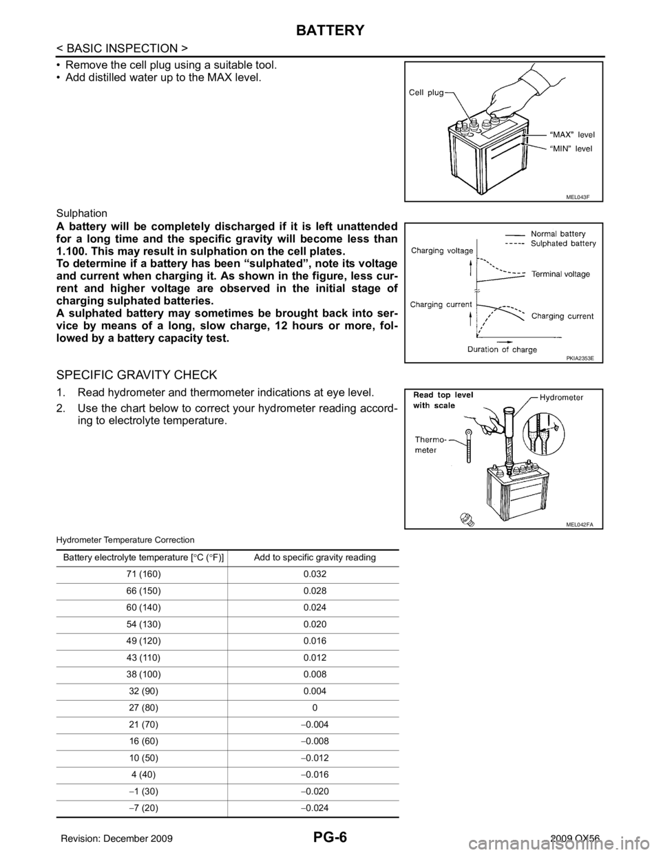
• Remove the cell plug using a suitable tool.
• Add distilled water up to the MAX level.
Sulphation
A battery will be completely discharged if it is left unattended
for a long time and the specific gravity will become less than
1.100. This may result in sulphation on the cell plates.
To determine if a battery has been “sulphated”, note its voltage
and current when charging it. As shown in the figure, less cur-
rent and higher voltage are observed in the initial stage of
charging sulphated batteries.
A sulphated battery may sometimes be brought back into ser-
vice by means of a long, slow charge, 12 hours or more, fol-
lowed by a battery capacity test.
SPECIFIC GRAVITY CHECK
1. Read hydrometer and thermometer indications at eye level.
2. Use the chart below to correct your hydrometer reading accord- ing to electrolyte temperature.
Hydrometer Temperature Correction
MEL043F
PKIA2353E
MEL042FA
Battery electrolyte temperature [° C (°F)] Add to specific gravity reading
71 (160) 0.032
66 (150) 0.028
60 (140) 0.024
54 (130) 0.020
49 (120) 0.016
43 (110) 0.012
38 (100) 0.008
32 (90) 0.004
27 (80) 0
21 (70) −0.004
16 (60) −0.008
10 (50) −0.012
4 (40) −0.016
− 1 (30) −0.020
− 7 (20) −0.024
Revision: December 20092009 QX56
Page 2912 of 4171

PG
HARNESSPG-41
< COMPONENT DIAGNOSIS >
C
DE
F
G H
I
J
K L
B A
O P
N
HARNESS
Harness LayoutINFOID:0000000003776571
HOW TO IDENTIFY TYPE A AND TYPE B MAIN HARNESSES
The differences between Type A and type B harnesses are minimal and mainly consist of differences in the cir-
cuit connections to the fuse block (J/B).
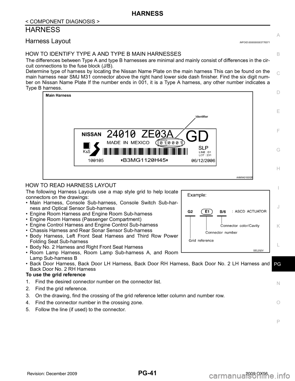
Determine type of harness by locating the Nissan Name Plate on the main harness This can be found on the
main harness near SMJ M31 connector above the right hand
lower side dash finisher. Find the six digit num-
ber on Nissan Name Plate If the number ends in 001, it is a Type A harness, any other number indicates a
Type B harness.
HOW TO READ HARNESS LAYOUT
The following Harness Layouts use a map style grid to help locate
connectors on the drawings:
• Main Harness, Console Sub-harness, Console Switch Sub-har-
ness and Optical Sensor Sub-harness
• Engine Room Harness and Engine Room Sub-harness
• Engine Room Harness (Passenger Compartment)
• Engine Control Harness and Engine Control Sub-harness
• Chassis Harness and Rear Sonar Sensor Sub-harness
• Body Harness, Left Front Seat Harness and Third Row Power Folding Seat Sub-harness
• Body No. 2 Harness and Right Front Seat Harness
• Room Lamp Harness, Room Lamp Sub-harness A, and Room
Lamp Sub-harness B
• Back Door Harness, Back Door LH Harness, Back Door RH Harness, Back Door No. 2 LH Harness and
Back Door No. 2 RH Harness
To use the grid reference
1. Find the desired connector number on the connector list.
2. Find the grid reference.
3. On the drawing, find the crossing of the grid reference letter column and number row.
4. Find the connector number in the crossing zone.
5. Follow the line (if used) to the connector.
AAMIA0100GB
SEL252V
Revision: December 20092009 QX56
Page 2915 of 4171

PG-44
< COMPONENT DIAGNOSIS >
HARNESS
A3 M6 W/10 : To E10A3 M82 W/2 : Circuit breaker-2
A2 M7 B/5 : Passenger select unlock relay G4 M84 W/16 : To B101
A3 M8 W/16 : To D2 A3 M85 W/3 : Tilt motor assembly
A2 M9 BR/24 : To D1 B3 M86 W/2 : Tilt motor assembly
A3 M10 Y/4 : To E29 B3 M87 B/5 : Rear power vent window relay (open)
A3 M11 B/1 : Parking brake switch B3 M89 B/5 : Rear power vent window relay (close)
C3 M12 GR/6 : Key switch and ignition knob switch B3 M91 W/16 : To E26
D3 M13 BR/2 : Front passenger air bag OFF indicator A2 M92 B/6 : Power liftgate switch
A2 M14 GR/6 : Diode-3 D1 M93 W/24 : Display unit
B3 M15 W/4 : Steering lock solenoid A2 M95 W/6 : Rear power vent window switch
A2 M16 GR/6 : ADP steering switch A2 M96 BR/6 : Pedal adjusting switch
B2 M17 W/8 : Steering angle sensor C2 M98 W/16 : A/C and AV switch assembly
C2 M18 W/40 : BCM (body control module) C3 M99 BR/2 : Foot lamp LH
C2 M19 W/15 : BCM (body control module) F4 M100 BR/2 : Foot lamp RH
C2 M20 B/15 : BCM (body control module) E3 M104 W/4 : Aux jack
C3 M21 W/4 : NATS antenna AMP. F2 M105 Y/2 : Front passenger air bag module
C3 M22 W/16 : Data link connector F2 M106 O/2 : Front passenger air bag module
B1 M23 W/12 : Combination meter F3 M107 B/5 : Front blower relay
C1 M24 W/40 : Combination meter D5 M108 B/6 : Yaw rate/ side/ decel G sensor
F2 M25 B/4 : Remote keyless entry receiver A1 M109 BR/2 : Front tweeter LH
B2 M26 W/6 : Ignition switch D2 M110 BR/2 : Center speaker
B2 M28 W/16 : Combination switch F2 M111 BR/2 : Front tweeter RH
B2 M29 Y/6 : Combination switch (spiral cable) C2 M112 BR/14 : BOSE speaker amp.
B3 M30 GR/8 : Combination switch (spiral cable) C2 M113 BR/23 : BOSE speaker amp.
G4 M31 SMJ : To E152 A2 M116 GR/8 : Sonar system OFF switch
C3 M32 W/4 : In-vehicle sensor A2 M117 GR/8 : Rear sonar system OFF switch
B3 M33 W/32 : Automatic drive position control unit B1 M118 B/2 : Front sonar buzzer
B3 M34 W/16 : Automatic drive position control unit F2 M120 W/4 : Remote keyless entry receiver
C5 M35 Y/28 : Air bag diagnosis sensor unit F4 M122 W/4 : Variable blower control (front)
G4 M36 SMJ : To B149 C3 M123 W/2 : Tire pressure warning check connector
G3 M37 B/1 : Fuse block (J/B) D2 M139 B/2 : Diode-1
G3 M38 B/2 : Fuse block (J/B) D1 M140 B/2 : Diode-2
D3 M39 W/8 : Fuse block (J/B) C2 M141 GR/8 : 4WD shift switch
A3 M40 SMJ : To B69 E1 M142 B/6 : Mode door motor (front)
D2 M42 W/20 : AV control unit E3 M143 B/6 : Air mix door motor (passenger)
D2 M43 W/12 : AV control unit C1 M144 B/6 : Defroster door motor
D2 M44 W/32 : AV control unit E3 M146 GR/2 : Intake sensor
D3 M45 W/40 : AV control unit D3 M147B/6 : Air mix doo r motor (driver)
B1 M47 B/2 : Sonar buzzer D2 M148 W/4 : Headlamp aiming switch
D2 M49 B/26 : A/C auto amp. D3 M149 W/4 : Clock
D2 M50 L/26 : A/C auto amp. B1 M150 W/2 : Ignition keyhole illumination
B3 M51 L/4 : Trailer tow relay 1 A3 M158 W/10 : To D3
B2 M52 W/2 : Combination switch (spiral cable) Console sub-harness
D3 M53 B/3 : Front power socket LH D4 M201 W/16 : To M56
E3 M54 B/3 : Front power socket RH (for cigarette
lighter) D4 M202 BR/24 : To M64
Revision: December 20092009 QX56
Page 2950 of 4171

PWC-2
PASSENGER SIDE : Description ...........................25
PASSENGER SIDE : Compo nent Function Check
...
25
PASSENGER SIDE : Diagnosis Procedure ........ ...25
REAR LH ................................................................ ...28
REAR LH : Description ...........................................28
REAR LH : Component Function Check ................28
REAR LH : Diagnosis Procedure ............................28
REAR RH ............................................................... ...30
REAR RH : Description ..........................................31
REAR RH : Component Function Check ................31
REAR RH : Diagnosis Procedure ...........................31
DOOR SWITCH .................................................34
Description ........................................................... ...34
Component Function Check ...................................34
Diagnosis Procedure ..............................................34
Component Inspection ............................................35
DOOR KEY CYLINDER SWITCH ......................36
Description ........................................................... ...36
Component Function Check ...................................36
Diagnosis Procedure ..............................................36
Component Inspection ............................................37
POWER WINDOW SERIAL LINK .....................39
POWER WINDOW MAIN SWITCH ........................ ...39
POWER WINDOW MAIN SWITCH : Description ...39
POWER WINDOW MAIN SWITCH : Component
Function Check .......................................................
39
POWER WINDOW MAIN SWITCH : Diagnosis
Procedure ...............................................................
39
FRONT POWER WINDOW SWITCH ..................... ...40
FRONT POWER WINDOW SWITCH : Descrip-
tion ..........................................................................
40
FRONT POWER WINDOW SWITCH : Compo-
nent Function Check ...............................................
40
FRONT POWER WINDOW SWITCH : Diagnosis
Procedure ...............................................................
41
REAR POWER WINDOW SWITCH ....................... ...42
REAR POWER WINDOW SWITCH : Power Win-
dow Serial Link Check Rear LH or RH ...................
42
POWER WINDOW LOCK SWITCH ...................43
Description ........................................................... ...43
Component Function Check ...................................43
REAR POWER VENT WINDOW SWITCH
CIRCUIT CHECK ...............................................
44
Description ........................................................... ...44
Diagnosis Procedure - (Early Production) ..............44
Diagnosis Procedure - (Late Production) ...............44
REAR POWER VENT WINDOW MOTOR LH
CIRCUIT CHECK ...............................................
46
Description ........................................................... ...46
Diagnosis Procedure ..............................................46
REAR POWER VENT WINDOW MOTOR RH
CIRCUIT CHECK ...............................................
47
Description ........................................................... ...47
Diagnosis Procedure ...............................................47
REAR POWER VENT WINDOW RELAY
(OPEN) CHECK .................................................
48
Description ........................................................... ...48
Diagnosis Procedure - (Early Production) ...............48
Diagnosis Procedure - (Late Production) ............. ...49
REAR POWER VENT WINDOW RELAY
(CLOSE) CHECK ...............................................
51
Description ........................................................... ...51
Diagnosis Procedure - (Early Production) ...............51
Diagnosis Procedure - (Late Production) ............. ...52
ECU DIAGNOSIS .......................................54
BCM (BODY CONTROL MODULE) ............... ...54
Reference Value .................................................. ...54
Terminal Layout ......................................................56
Physical Values .......................................................56
Wiring Diagram .......................................................62
POWER WINDOW MAIN SWITCH ...................67
Reference Value .................................................. ...67
Wiring Diagram .......................................................69
Fail Safe .................................................................80
FRONT POWER WINDOW SWITCH ................82
Reference Value .................................................. ...82
Wiring Diagram .......................................................84
Fail Safe .................................................................95
SYMPTOM DIAGNOSIS ............................97
NONE OF THE POWER WINDOWS CAN BE
OPERATED USING ANY SWITCH ................ ...
97
Diagnosis Procedure ............................................ ...97
DRIVER SIDE POWER WINDOW ALONE
DOES NOT OPERATE ......................................
98
Diagnosis Procedure ............................................ ...98
FRONT PASSENGER SIDE POWER WIN-
DOW ALONE DOES NOT OPERATE ...............
99
Diagnosis Procedure ............................................ ...99
REAR LH SIDE POWER WINDOW ALONE
DOES NOT OPERATE .....................................
100
Diagnosis Procedure ............................................ .100
REAR RH SIDE POWER WINDOW ALONE
DOES NOT OPERATE .....................................
101
Diagnosis Procedure ............................................ .101
ANTI-PINCH SYSTEM DOES NOT OPERATE
NORMALLY (DRIVER SIDE) ...........................
102
Diagnosis Procedure ............................................ .102
Revision: December 20092009 QX56
Page 3048 of 4171

PWC-100
< SYMPTOM DIAGNOSIS >
REAR LH SIDE POWER WINDOW ALONE DOES NOT OPERATE
REAR LH SIDE POWER WINDOW ALONE DOES NOT OPERATE
Diagnosis ProcedureINFOID:0000000003776041
1. CHECK REAR POWER WINDOW SWITCH LH
Check rear power window switch LH.
Refer to PWC-15, "REAR POWER WINDOW SW ITCH : Component Function Check"
.
Is the inspection result normal?
YES >> GO TO 2
NO >> Repair or replace the malfunctioning parts.
2. CHECK REAR POWER WINDOW MOTOR LH
Check rear power window motor LH.
Refer to PWC-20, "REAR LH : Component Function Check"
.
Is the inspection result normal?
YES >> Inspection End.
NO >> Check intermittent incident. Refer to GI-38, "Intermittent Incident"
.
Revision: December 20092009 QX56