2009 INFINITI QX56 100
[x] Cancel search: 100Page 3687 of 4171
U1000 CAN COMM CIRCUITTM-39
< COMPONENT DIAGNOSIS >
CEF
G H
I
J
K L
M A
B
TM
N
O P
COMPONENT DIAGNOSIS
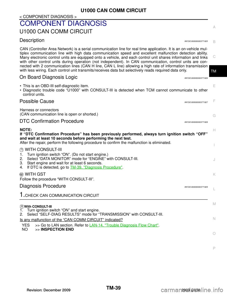
U1000 CAN COMM CIRCUIT
DescriptionINFOID:0000000003771825
CAN (Controller Area Network) is a serial communication li ne for real time application. It is an on-vehicle mul-
tiplex communication line with high data communica tion speed and excellent malfunction detection ability.
Many electronic control units are equipped onto a vehicl e, and each control unit shares information and links
with other control units during operation (not independent ). In CAN communication, control units are con-
nected with 2 communication lines (CAN H line, CAN L li ne) allowing a high rate of information transmission
with less wiring. Each control unit transmits/recei ves data but selectively reads required data only.
On Board Diagnosis LogicINFOID:0000000003771826
This is an OBD-III self-diagnostic item.
Diagnostic trouble code “U1000” with CONSULT-III is detected when TCM cannot communicate to other
control units.
Possible CauseINFOID:0000000003771827
Harness or connectors
(CAN communication line is open or shorted.)
DTC Confirmation ProcedureINFOID:0000000003771828
NOTE:
If “DTC Confirmation Procedure” has been previously performed, always turn ignition switch “OFF”
and wait at least 10 seconds before performing the next test.
After the repair, perform the following procedure to confirm the malfunction is eliminated.
WITH CONSULT-III
1. Turn ignition switch “ON”. (Do not start engine.)
2. Select “DATA MONITOR” mode for “ENGINE” with CONSULT-III.
3. Start engine and wait for at least 6 seconds.
4. If DTC is detected, go to TM-39, "Diagnosis Procedure"
.
WITH GST
Follow the procedure “WITH CONSULT-III”.
Diagnosis ProcedureINFOID:0000000003771829
1.CHECK CAN COMMUNICATION CIRCUIT
With CONSULT-III1. Turn ignition switch “ON” and start engine.
2. Select “SELF-DIAG RESULTS” mode for “TRANSMISSION” with CONSULT-III.
Is any malfunction of the
“CAN COMM CIRCUIT” indicated?
YES >> Go to LAN section. Refer to LAN-14, "Trouble Diagnosis Flow Chart".
NO >> INSPECTION END
Revision: December 20092009 QX56
Page 3748 of 4171
TM-100
< COMPONENT DIAGNOSIS >
A/T SHIFT LOCK SYSTEM
ABDIA0045GB
Revision: December 20092009 QX56
Page 3765 of 4171
TCM
TM-117
< ECU DIAGNOSIS >
C EF
G H
I
J
K L
M A
B
TM
N
O P
High and Low Revers
e Clutch Solenoid
If a (electrical or functional) malfunction occurs with the solenoid either “ON” or “OFF”, the transmission is
held in 4th gear to make driving possible.
Input Speed Sensor 1 or 2
The control is the same as if there were no input speed sensors, 5GR is prohibited.
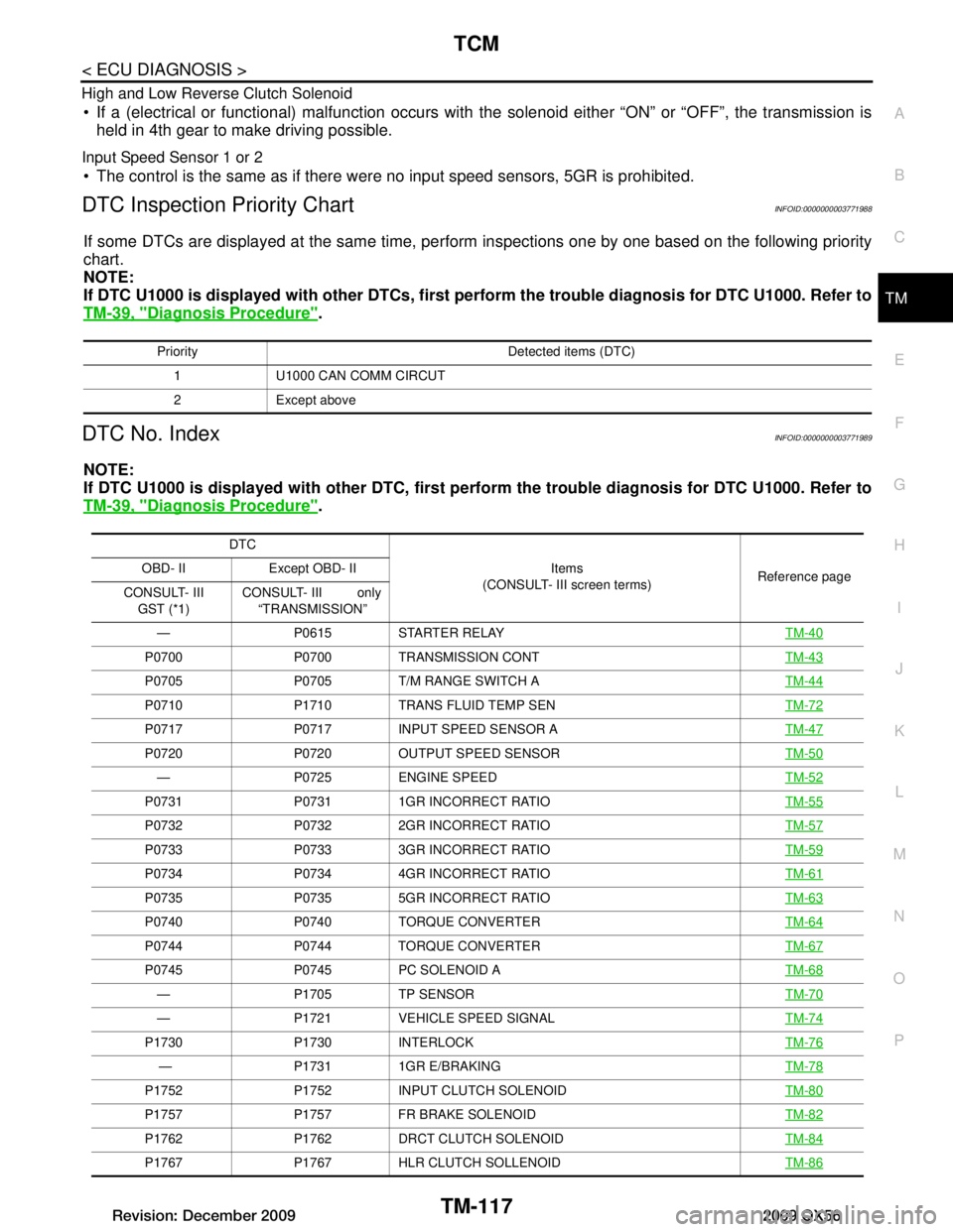
DTC Inspection Priority ChartINFOID:0000000003771988
If some DTCs are displayed at the same time, per form inspections one by one based on the following priority
chart.
NOTE:
If DTC U1000 is displayed with other DTCs, first pe rform the trouble diagnosis for DTC U1000. Refer to
TM-39, "Diagnosis Procedure"
.
DTC No. IndexINFOID:0000000003771989
NOTE:
If DTC U1000 is displayed with other DTC, first pe rform the trouble diagnosis for DTC U1000. Refer to
TM-39, "Diagnosis Procedure"
.
Priority Detected items (DTC)
1 U1000 CAN COMM CIRCUT
2 Except above
DTC Items
(CONSULT- III screen terms) Reference page
OBD- II Except OBD- II
CONSULT- III GST (*1) CONSULT- III only
“TRANSMISSION”
— P0615 STARTER RELAY TM-40
P0700 P0700 TRANSMISSION CONT TM-43
P0705 P0705 T/M RANGE SWITCH ATM-44
P0710 P1710 TRANS FLUID TEMP SENTM-72
P0717 P0717 INPUT SPEED SENSOR ATM-47
P0720 P0720 OUTPUT SPEED SENSORTM-50
— P0725 ENGINE SPEEDTM-52
P0731 P0731 1GR INCORRECT RATIO TM-55
P0732 P0732 2GR INCORRECT RATIOTM-57
P0733 P0733 3GR INCORRECT RATIOTM-59
P0734 P0734 4GR INCORRECT RATIOTM-61
P0735 P0735 5GR INCORRECT RATIOTM-63
P0740 P0740 TORQUE CONVERTERTM-64
P0744 P0744 TORQUE CONVERTERTM-67
P0745 P0745 PC SOLENOID ATM-68
— P1705 TP SENSORTM-70
— P1721 VEHICLE SPEED SIGNALTM-74
P1730 P1730 INTERLOCK TM-76
— P1731 1GR E/BRAKINGTM-78
P1752 P1752 INPUT CLUTCH SOLENOID TM-80
P1757 P1757 FR BRAKE SOLENOIDTM-82
P1762 P1762 DRCT CLUTCH SOLENOIDTM-84
P1767 P1767 HLR CLUTCH SOLLENOIDTM-86
Revision: December 20092009 QX56
Page 3766 of 4171
TM-118
< ECU DIAGNOSIS >
TCM
*1: These numbers are prescribed by SAE J2012.
*2: These malfunctions cannot be displayed MIL if another malfunction is assigned to MIL.
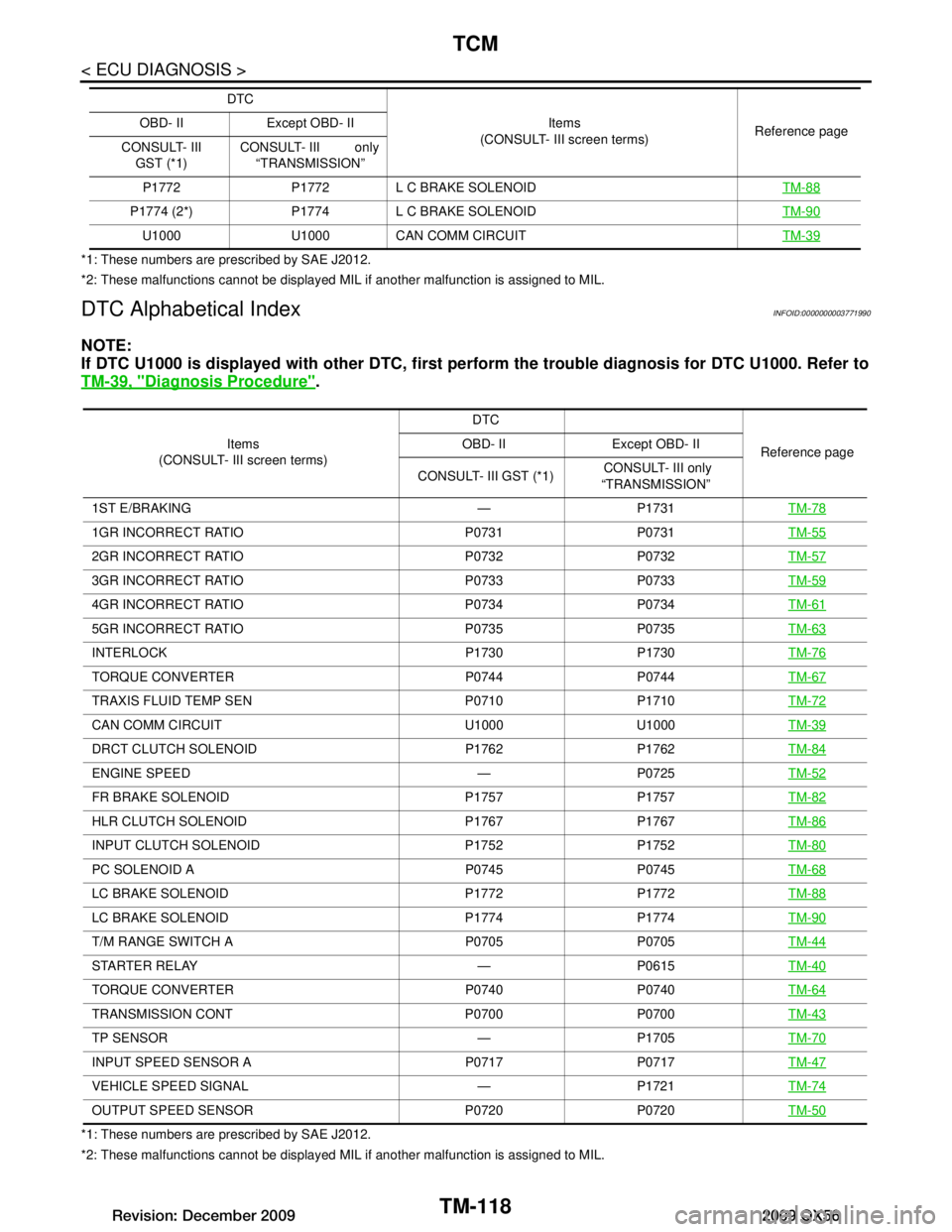
DTC Alphabetical IndexINFOID:0000000003771990
NOTE:
If DTC U1000 is displayed with other DTC, first perform the trouble diagnosis for DTC U1000. Refer to
TM-39, "Diagnosis Procedure"
.
*1: These numbers are prescribed by SAE J2012.
*2: These malfunctions cannot be displayed MIL if another malfunction is assigned to MIL. P1772 P1772 L C BRAKE SOLENOID
TM-88
P1774 (2*) P1774 L C BRAKE SOLENOID TM-90
U1000 U1000 CAN COMM CIRCUITTM-39
DTC
Items
(CONSULT- III screen terms) Reference page
OBD- II Except OBD- II
CONSULT- III GST (*1) CONSULT- III only
“TRANSMISSION”
Items
(CONSULT- III screen terms) DTC
Reference page
OBD- II Except OBD- II
CONSULT- III GST (*1) CONSULT- III only
“TRANSMISSION”
1ST E/BRAKING — P1731 TM-78
1GR INCORRECT RATIO P0731 P0731TM-55
2GR INCORRECT RATIO P0732 P0732TM-57
3GR INCORRECT RATIO P0733 P0733TM-59
4GR INCORRECT RATIO P0734 P0734TM-61
5GR INCORRECT RATIO P0735 P0735TM-63
INTERLOCK P1730 P1730TM-76
TORQUE CONVERTER P0744 P0744 TM-67
TRAXIS FLUID TEMP SEN P0710 P1710TM-72
CAN COMM CIRCUIT U1000 U1000TM-39
DRCT CLUTCH SOLENOID P1762 P1762 TM-84
ENGINE SPEED — P0725 TM-52
FR BRAKE SOLENOID P1757 P1757TM-82
HLR CLUTCH SOLENOID P1767 P1767TM-86
INPUT CLUTCH SOLENOID P1752 P1752TM-80
PC SOLENOID A P0745 P0745TM-68
LC BRAKE SOLENOID P1772 P1772TM-88
LC BRAKE SOLENOID P1774 P1774 TM-90
T/M RANGE SWITCH A P0705 P0705TM-44
STARTER RELAY — P0615TM-40
TORQUE CONVERTER P0740 P0740TM-64
TRANSMISSION CONT P0700 P0700TM-43
TP SENSOR — P1705TM-70
INPUT SPEED SENSOR A P0717 P0717TM-47
VEHICLE SPEED SIGNAL — P1721TM-74
OUTPUT SPEED SENSOR P0720 P0720TM-50
Revision: December 20092009 QX56
Page 3825 of 4171
PREPARATIONTM-177
< PREPARATION >
CEF
G H
I
J
K L
M A
B
TM
N
O P
PREPARATION
PREPARATION
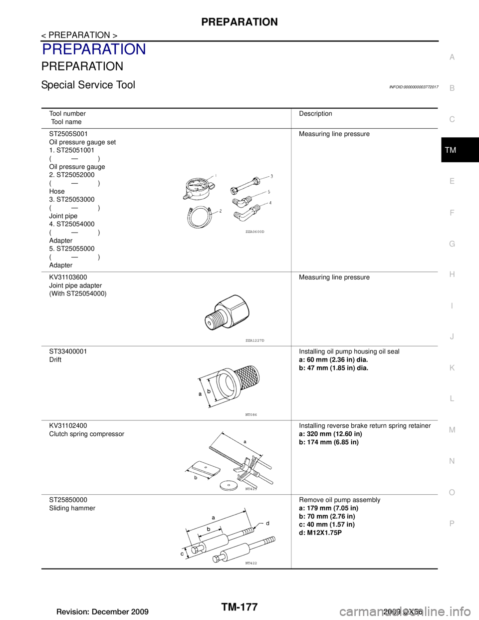
Special Service ToolINFOID:0000000003772017
Tool number
Tool name Description
ST2505S001
Oil pressure gauge set
1. ST25051001
(—)
Oil pressure gauge
2. ST25052000
(—)
Hose
3. ST25053000
(—)
Joint pipe
4. ST25054000
(—)
Adapter
5. ST25055000
(—)
Adapter Measuring line pressure
KV31103600
Joint pipe adapter
(With ST25054000) Measuring line pressure
ST33400001
Drift Installing oil pump housing oil seal
a: 60 mm (2.36 in) dia.
b: 47 mm (1.85 in) dia.
KV31102400
Clutch spring compressor Installing reverse brake
return spring retainer
a: 320 mm (12.60 in)
b: 174 mm (6.85 in)
ST25850000
Sliding hammer Remove oil pump assembly
a: 179 mm (7.05 in)
b: 70 mm (2.76 in)
c: 40 mm (1.57 in)
d: M12X1.75P
ZZA0600D
ZZA1227D
NT086
NT423
NT422
Revision: December 20092009 QX56
Page 3938 of 4171
TM-290
< SERVICE DATA AND SPECIFICATIONS (SDS)
SERVICE DATA AND SPECIFICATIONS (SDS)
SERVICE DATA AND SPECIFICATIONS (SDS)
SERVICE DATA AND SPECIFICATIONS (SDS)
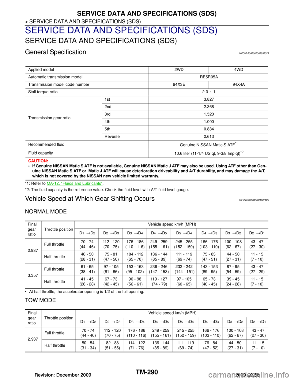
General SpecificationINFOID:0000000005892329
*1: Refer to MA-12, "Fluids and Lubricants".
*2: The fluid capacity is the reference value. Check the fluid level with A/T fluid level gauge.
Vehicle Speed at Which Gear Shifting OccursINFOID:0000000004187500
NORMAL MODE
At half throttle, the accelerator opening is 1/2 of the full opening.
TOW MODE
Applied model 2WD 4WD
Automatic transmission model RE5R05A
Transmission model code number 94X3E 94X4A
Stall torque ratio 2.0 : 1
Transmission gear ratio 1st 3.827
2nd 2.368
3rd 1.520
4th 1.000
5th 0.834
Reverse 2.613
Recommended fluid Genuine NISSAN Matic S ATF
*1
Fluid capacity10.6 liter (11-1/4 US qt, 9-3/8 Imp qt)*2
CAUTION:
If Genuine NISSAN Matic S ATF is not available, Genuine NISSAN Matic J ATF may also be used. Using ATF other than Gen-
uine NISSAN Matic S ATF or Matic J ATF will cause deterioration driveability and A/T durability, and may damage the A/T,
which is not covered by the NISSAN new vehicle limited warranty.
Final
gear
ratio Throttle position
Vehicle speed km/h (MPH)
D
1 → D2D2 → D3D3 → D4D4 → D5D5 → D4D4 → D3D3 → D2D2 → D1
2.937 Full throttle
70 - 74
(44 - 46) 112 - 120
(70 - 75) 176 - 186
(110 - 116) 249 - 259
(155 - 161) 245 - 255
(152 - 159) 166 - 176
(103 - 110) 100 - 108
(62 - 67) 43 - 47
(27 - 30)
Half throttle 46 - 50
(28 - 31) 75 - 81
(47 - 50) 104 - 112
(65 - 70) 136 - 144
(85 - 89) 111 - 11 9
(69 - 74) 75 - 83
(47 - 51) 44 - 50
(27 - 31) 11 - 1 5
(7 - 10)
3.357 Full throttle
61 - 65
(38 - 41) 97 - 105
(61 - 66) 153 - 163
(95 - 102) 236 - 246
(147 - 153) 232 - 242
(144 - 151) 143 - 153
(89 - 95) 87 - 95
(54 - 59) 43 - 47
(27 - 29)
Half throttle 41 - 45
(26 - 28) 67 - 73
(42 - 45) 90 - 98
(56 - 61) 119 - 127
(74 - 79) 97 - 105
(60 - 65) 65 - 73
(40 - 45) 39 - 45
(24 - 28) 11 - 1 5
(7 - 10)
Final
gear
ratio Throttle position Vehicle speed km/h (MPH)
D
1 → D2D2 → D3D3 → D4D4 → D5D5 → D4D4 → D3D3 → D2D2 → D1
2.937 Full throttle
70 - 74
(44 - 46) 112 - 120
(70 - 75) 176 - 186
(110 - 116) 249 - 259
(155 - 161) 245 - 255
(152 - 159) 166 - 176
(103 - 110) 100 - 108
(62 - 67) 43 - 47
(27 - 30)
Half throttle 50 - 54
(31 - 34) 82 - 88
(51 - 55) 114 - 122
(71 - 76) 136 - 144
(85 - 89) 111 - 11 9
(69 - 74) 76 - 84
(47 - 52) 44 - 50
(27 - 31) 11 - 1 5
(7 - 10)
Revision: December 20092009 QX56
Page 3939 of 4171

SERVICE DATA AND SPECIFICATIONS (SDS)
TM-291
< SERVICE DATA AND SPECIFICATIONS (SDS)
C EF
G H
I
J
K L
M A
B
TM
N
O P
At half throttle, the accelerator opening is 1/2 of the full opening.
Vehicle Speed at Which Lock-up Occurs/ReleasesINFOID:0000000004187501
At closed throttle, the accelerator opening is less than 1/8 condition. (Closed throttle position signal OFF)
At half throttle, the accelerator opening is 1/2 of the full opening.
Stall SpeedINFOID:0000000004187502
Line PressureINFOID:0000000004187503
Input Speed SensorINFOID:0000000004187504
Output Speed SensorINFOID:0000000004187505
Reverse BrakeINFOID:0000000004187506
3.357Full throttle
61 - 65
(38 - 41) 97 - 105
(61 - 66) 153 - 163
(95 - 102) 236 - 246
(147 - 153) 232 - 242
(144 - 151) 143 - 153
(89 - 95) 87 - 95
(54 - 59) 43 - 47
(27 - 29)
Half throttle 46 - 50
(29 - 31) 73 - 79
(45 - 59) 99 - 107
(62 - 66) 11 9 - 1 2 7
(74 - 79) 97 - 105
(60 - 65) 65 - 73
(40 - 45) 39 - 45
(24 - 28) 11 - 1 5
(7 - 10)
Final gear ratio Throttle position Vehicle speed km/h (MPH)
Lock-up ON Lock-up OFF
2.937 Closed throttle 51 - 59 (3
2 - 36) 48 - 56 (30 - 34)
Half throttle 177 - 185 (110 - 115) 111 - 119 (69 - 73)
3.357 Closed throttle 44 - 52 (2
8 - 32) 41 - 49 (26 - 30)
Half throttle 161 - 169 (100 - 105) 97 - 105 (61 - 65)
Stall speed 2,550 - 2,850 rpm
Engine speedLine pressure kPa (kg/cm
2, psi)
“R” position “D” position
At idle speed 425 – 465 (4.3 – 4.7, 62 – 67) 379 – 428 (3.9 – 4.4, 55 – 62)
At stall speed 1,605 – 1,950 (16.4 – 19.9, 233 – 283) 1,310 – 1,500 (13.4 – 15.3, 190 – 218)
Name Condition Data (Approx.)
Input speed sensor 1 When running at 50 km/h (31 MPH) in 4th speed witch the closed throttle position
signal OFF.
1.3 kHz
Input speed sensor 2 When running at 20 km/h (12 MPH) in 1st speed witch the closed throttle position
signal OFF.
Name Condition Data (Approx.)
Output speed sensor When running at 20 km/h (12 MPH). 185 Hz
Number of drive plates 7
Number of driven plates 7
Clearance mm (in) Standard 0.7 – 1.1 (0.028 – 0.043)
Revision: December 20092009 QX56
Page 4024 of 4171
WCS
COMBINATION METERWCS-47
< ECU DIAGNOSIS >
C
DE
F
G H
I
J
K L
M B A
O P
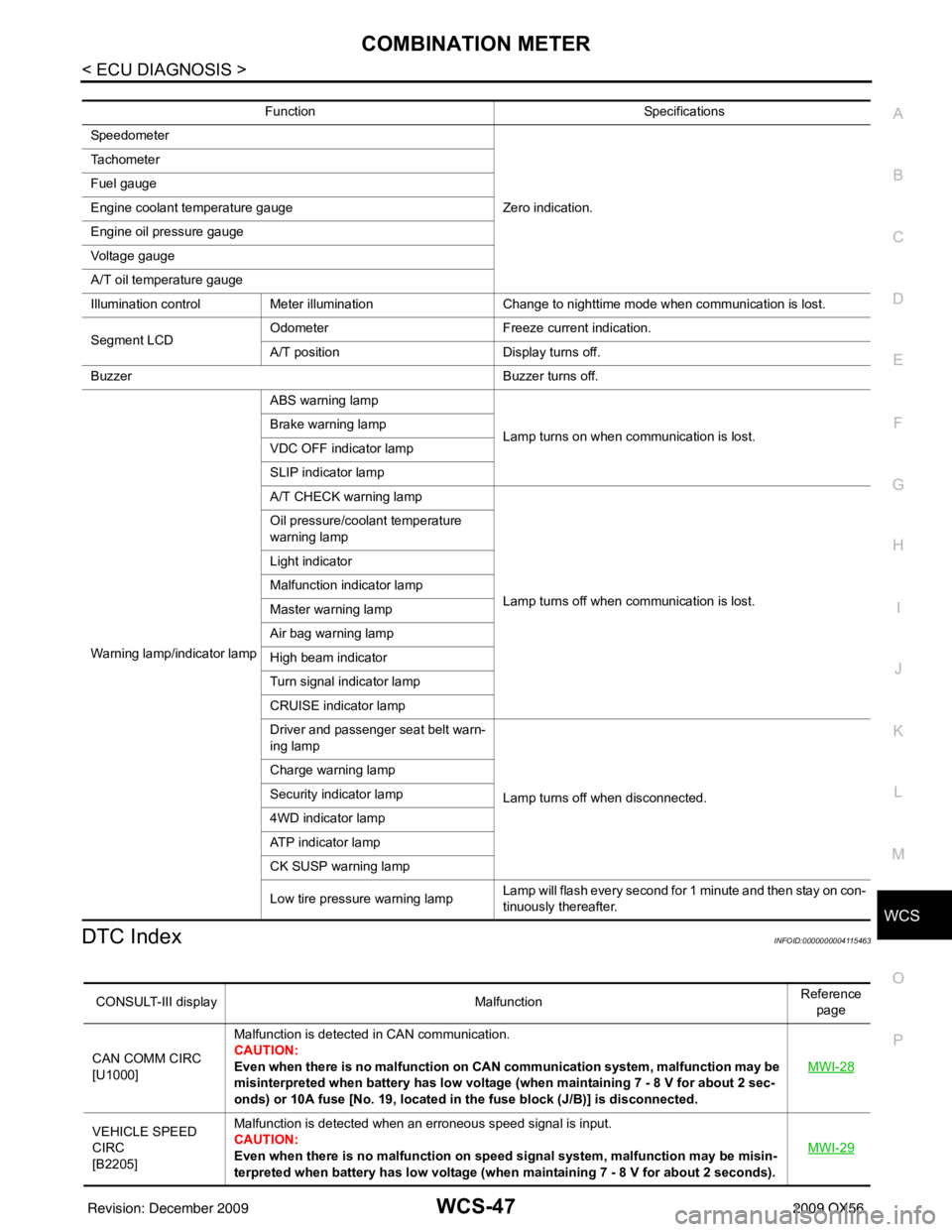
DTC IndexINFOID:0000000004115463
Function Specifications
Speedometer
Zero indication.
Tachometer
Fuel gauge
Engine coolant temperature gauge
Engine oil pressure gauge
Voltage gauge
A/T oil temperature gauge
Illumination control
Meter illumination Change to nighttime mode when communication is lost.
Segment LCD Odometer
Freeze current indication.
A/T position Display turns off.
Buzzer Buzzer turns off.
Warning lamp/indicator lamp ABS warning lamp
Lamp turns on when communication is lost.
Brake warning lamp
VDC OFF indicator lamp
SLIP indicator lamp
A/T CHECK warning lamp
Lamp turns off when communication is lost.
Oil pressure/coolant temperature
warning lamp
Light indicator
Malfunction indicator lamp
Master warning lamp
Air bag warning lamp
High beam indicator
Turn signal indicator lamp
CRUISE indicator lamp
Driver and passenger seat belt warn-
ing lamp
Lamp turns off when disconnected.
Charge warning lamp
Security indicator lamp
4WD indicator lamp
ATP indicator lamp
CK SUSP warning lamp
Low tire pressu
re warning lamp Lamp will flash every second for 1 minute and then stay on con-
tinuously thereafter.
CONSULT-III display
MalfunctionReference
page
CAN COMM CIRC
[U1000] Malfunction is detected in CAN communication.
CAUTION:
Even when there is no ma
lfunction on CAN communication system, malfunction may be
misinterpreted when battery has low voltag e (when maintaining 7 - 8 V for about 2 sec-
onds) or 10A fuse [No. 19, located in the fuse block (J/B)] is disconnected. MWI-28
VEHICLE SPEED
CIRC
[B2205]Malfunction is detected when an erroneous speed signal is input.
CAUTION:
Even when there is no malfunction on speed signal system, malfunction may be misin-
terpreted when battery has low voltage (whe
n maintaining 7 - 8 V for about 2 seconds). MWI-29
Revision: December 20092009 QX56