2009 INFINITI QX56 100
[x] Cancel search: 100Page 1831 of 4171
EM-8
< PREPARATION >
PREPARATION
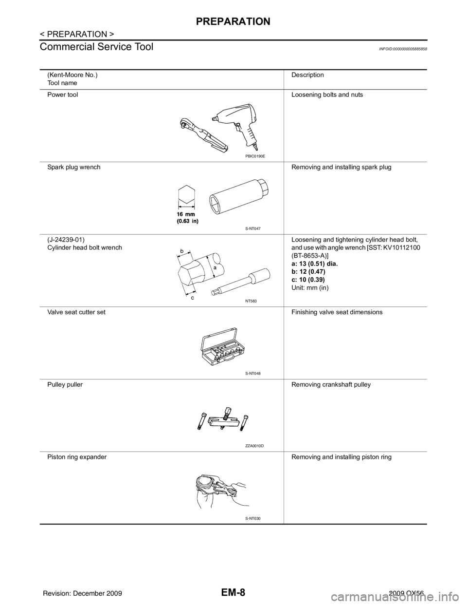
Commercial Service Tool
INFOID:0000000005885858
(Kent-Moore No.)
Tool name Description
Power tool Loosening bolts and nuts
Spark plug wrench Removing and installing spark plug
(J-24239-01)
Cylinder head bolt wrench Loosening and tightening cylinder head bolt,
and use with angle wrench [SST: KV10112100
(BT-8653-A)]
a: 13 (0.51) dia.
b: 12 (0.47)
c: 10 (0.39)
Unit: mm (in)
Valve seat cutter set Finishing valve seat dimensions
Pulley puller Removing crankshaft pulley
Piston ring expander Removing and installing piston ring
PBIC0190E
S-NT047
NT583
S-NT048
ZZA0010D
S-NT030
Revision: December 20092009 QX56
Page 1857 of 4171
EM-34
< ON-VEHICLE REPAIR >
OIL PAN AND OIL STRAINER
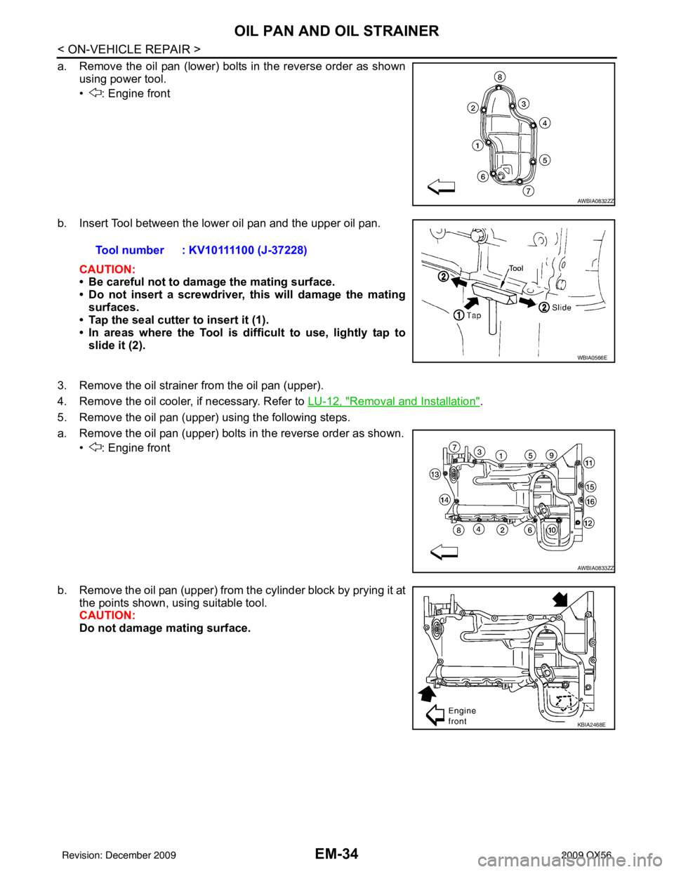
a. Remove the oil pan (lower) bolts in the reverse order as shownusing power tool.
• : Engine front
b. Insert Tool between the lower oil pan and the upper oil pan. CAUTION:
• Be careful not to damage the mating surface.
• Do not insert a screwdriver, this will damage the matingsurfaces.
• Tap the seal cutter to insert it (1).
• In areas where the Tool is diffi cult to use, lightly tap to
slide it (2).
3. Remove the oil strainer from the oil pan (upper).
4. Remove the oil cooler, if necessary. Refer to LU-12, "
Removal and Installation".
5. Remove the oil pan (upper) using the following steps.
a. Remove the oil pan (upper) bolts in the reverse order as shown. • : Engine front
b. Remove the oil pan (upper) from the cylinder block by prying it at the points shown, using suitable tool.
CAUTION:
Do not damage mating surface.
AWBIA0832ZZ
Tool number : KV10111100 (J-37228)
WBIA0566E
AWBIA0833ZZ
KBIA2468E
Revision: December 20092009 QX56
Page 1868 of 4171
TIMING CHAINEM-45
< ON-VEHICLE REPAIR >
C
DE
F
G H
I
J
K L
M A
EM
NP
O
Removal and InstallationINFOID:0000000005885887
NOTE:
• To remove timing chain and associated parts, start with those on the LH bank. The procedure for removing
parts on the RH bank is omitted because it is t he same as that for removal on the LH bank.
• To install timing chain and associated parts, start with those on the RH bank. The procedure for installing parts on the LH bank is omitted because it is t he same as that for installation on the RH bank.
REMOVAL
1. Remove the engine assembly from the vehicle. Refer to EM-78, "Removal and Installation".
2. Remove the following components and related parts: • Drive belt auto tensioner and idler pulley. Refer to EM-13, "
Removal and Installation".
• Thermostat housing and water hose. Refer to CO-22, "
Removal and Installation".
• Power steering oil pump bracket. Refer to ST-26, "
Removal and Installation".
• Oil pan (lower), (upper) and oil strainer. Refer to EM-33, "
Removal and Installation".
• Rocker cover. Refer to EM-38, "
Removal and Installation".
• Generator and generator bracket. Refer to CHG-20, "
Removal and Installation".
• Water pump. Refer to CO-20, "
Exploded View".
3. Disconnect and remove the camshaft position sensor.
4. Disconnect and remove the intake valve ti ming control position sensor (RH and LH).
5. Disconnect and remove the intake valve timing control solenoid valve (RH and LH).
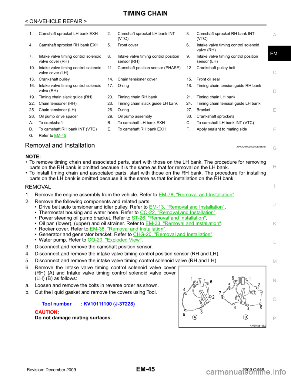
6. Remove the Intake valve timing control solenoid valve cover (RH) (A) and Intake valve timing control solenoid valve cover
(LH) (B) as follows:
a. Loosen and remove the bolts in reverse order as shown.
b. Cut the liquid gasket and remove the covers using Tool.
CAUTION:
Do not damage mating surfaces.
1. Camshaft sprocket LH bank EXH 2. Camshaft sprocket LH bank INT (VTC)3. Camshaft sprocket RH bank INT
(VTC)
4. Camshaft sprocket RH bank EXH 5. Front cover 6. Intake valve timing control solenoid
valve (RH)
7. Intake valve timing control solenoid valve cover (RH) 8. Intake valve timing control position
sensor (RH) 9. Intake valve timing control position
sensor (LH)
10. Intake valve timing control solenoid valve cover (LH) 11. Camshaft position
sensor (PHASE) 12 Cran kshaft pulley bolt
13. Crankshaft pulley 14. Chain tensioner cover 15. Front oil seal
16. Intake valve timing control solenoid valve (RH) 17. O-ring
18. Timing chain tension guide RH bank
19. Timing chain slack guide (RH) 20. Timing chain RH bank 21. Timing chain LH bank
22. Chain tensioner (RH) 23. Timing chain slack guide LH bank 24. Timing chain tension guide LH bank
25. Chain tensioner (LH) 26. O-ring 27. Bracket
28. Oil pump drive spacer 29. Oil pump assembly 30. Crankshaft sprockets
A. To crankshaft B. To camshaft LH bank EXH C. To camshaft LH bank INT (VTC)
D. To camshaft RH bank INT (VTC) E. To camshaft RH bank EXH F. Apply sealant to mating side
G. Refer to EM-45
Tool number : KV10111100 (J-37228)
AWBIA0815ZZ
Revision: December 20092009 QX56
Page 1869 of 4171
EM-46
< ON-VEHICLE REPAIR >
TIMING CHAIN
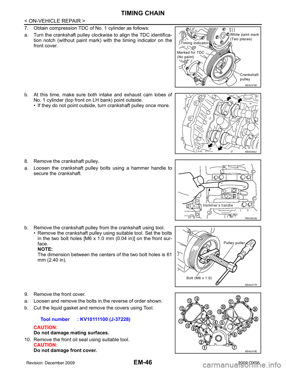
7. Obtain compression TDC of No. 1 cylinder as follows:
a. Turn the crankshaft pulley clockwise to align the TDC identifica-tion notch (without paint mark) with the timing indicator on the
front cover.
b. At this time, make sure both intake and exhaust cam lobes of No. 1 cylinder (top front on LH bank) point outside.
• If they do not point outside, turn crankshaft pulley once more.
8. Remove the crankshaft pulley.
a. Loosen the crankshaft pulley bolts using a hammer handle to secure the crankshaft.
b. Remove the crankshaft pulley from the crankshaft using tool. • Remove the crankshaft pulley using suitable tool. Set the boltsin the two bolt holes [M6 x 1.0 mm (0.04 in)] on the front sur-
face.
NOTE:
The dimension between the centers of the two bolt holes is 61
mm (2.40 in).
9. Remove the front cover.
a. Loosen and remove the bolts in the reverse of order shown.
b. Cut the liquid gasket and remove the covers using Tool. CAUTION:
Do not damage mating surfaces.
10. Remove the front oil seal using suitable tool. CAUTION:
Do not damage front cover.
KBIA2476E
KBIA0400J
PBIC0053E
KBIA2477E
Tool number : KV10111100 (J-37228)
KBIA2478E
Revision: December 20092009 QX56
Page 1877 of 4171
EM-54
< ON-VEHICLE REPAIR >
CAMSHAFT
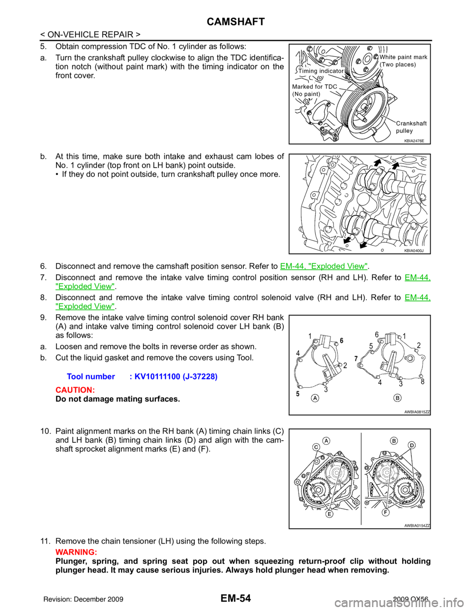
5. Obtain compression TDC of No. 1 cylinder as follows:
a. Turn the crankshaft pulley clockwise to align the TDC identifica-tion notch (without paint mark) with the timing indicator on the
front cover.
b. At this time, make sure both intake and exhaust cam lobes of No. 1 cylinder (top front on LH bank) point outside.
• If they do not point outside, turn crankshaft pulley once more.
6. Disconnect and remove the camshaft position sensor. Refer to EM-44, "
Exploded View".
7. Disconnect and remove the intake valve timing c ontrol position sensor (RH and LH). Refer to EM-44,
"Exploded View".
8. Disconnect and remove the intake valve timing control solenoid valve (RH and LH). Refer to EM-44,
"Exploded View".
9. Remove the intake valve timing control solenoid cover RH bank (A) and intake valve timing control solenoid cover LH bank (B)
as follows:
a. Loosen and remove the bolts in reverse order as shown.
b. Cut the liquid gasket and remove the covers using Tool.
CAUTION:
Do not damage mating surfaces.
10. Paint alignment marks on the RH bank (A) timing chain links (C) and LH bank (B) timing chain links (D) and align with the cam-
shaft sprocket alignment marks (E) and (F).
11. Remove the chain tensioner (LH) using the following steps. WARNING:
Plunger, spring, and spring seat pop out when squeezing return-proof clip without holding
plunger head. It may cause serious injuries. Always hold plunger head when removing.
KBIA2476E
KBIA0400J
Tool number : KV10111100 (J-37228)
AWBIA0815ZZ
AWBIA0154ZZ
Revision: December 20092009 QX56
Page 1878 of 4171
CAMSHAFTEM-55
< ON-VEHICLE REPAIR >
C
DE
F
G H
I
J
K L
M A
EM
NP
O
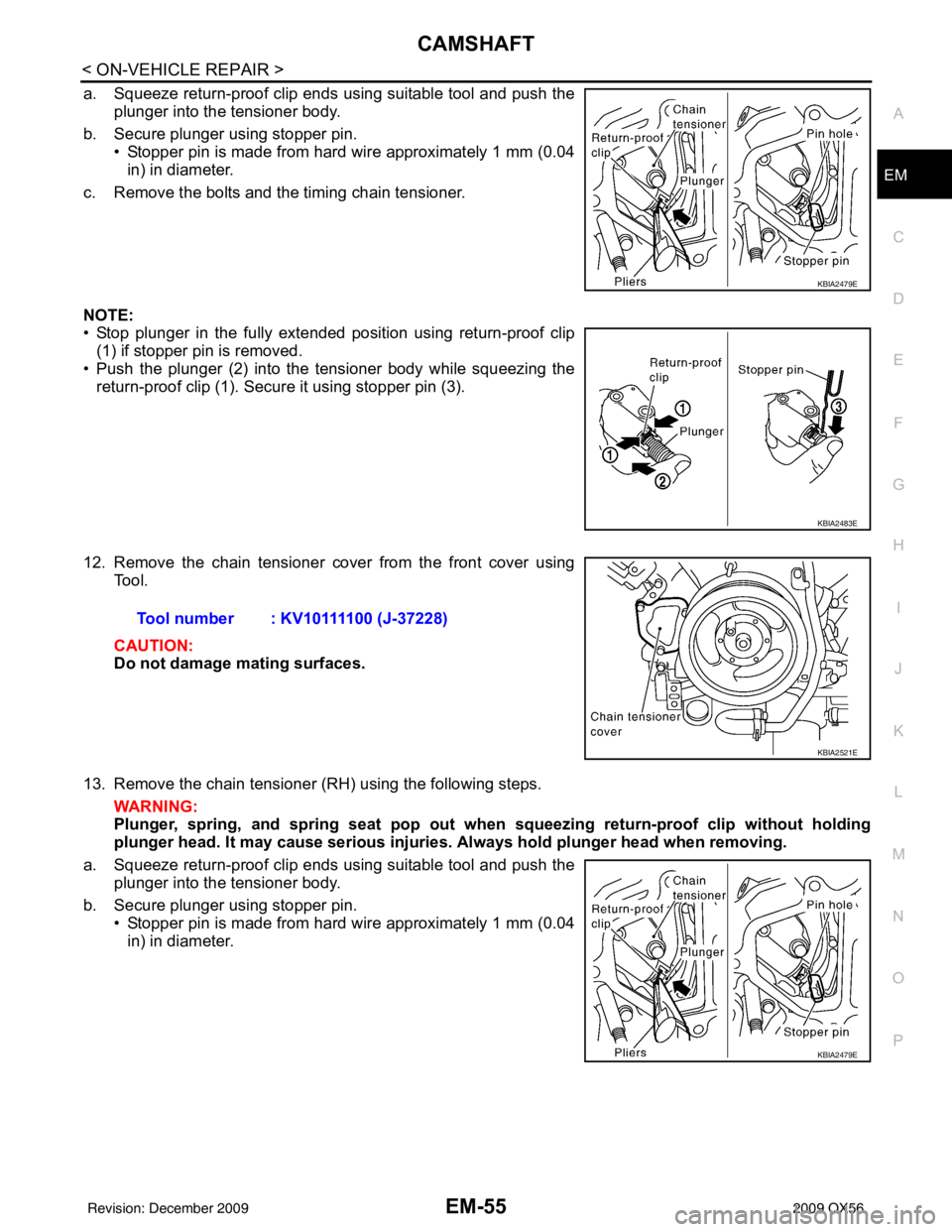
a. Squeeze return-proof clip ends using suitable tool and push the
plunger into the tensioner body.
b. Secure plunger using stopper pin. • Stopper pin is made from hard wire approximately 1 mm (0.04in) in diameter.
c. Remove the bolts and the timing chain tensioner.
NOTE:
• Stop plunger in the fully extended position using return-proof clip (1) if stopper pin is removed.
• Push the plunger (2) into the tensioner body while squeezing the return-proof clip (1). Secure it using stopper pin (3).
12. Remove the chain tensioner cover from the front cover using Tool.
CAUTION:
Do not damage mating surfaces.
13. Remove the chain tensioner (RH) using the following steps. WARNING:
Plunger, spring, and spring seat pop out when squeezing return -proof clip without holding
plunger head. It may cause serious injuries. Always hold plunger head when removing.
a. Squeeze return-proof clip ends using suitable tool and push the plunger into the tensioner body.
b. Secure plunger using stopper pin. • Stopper pin is made from hard wire approximately 1 mm (0.04in) in diameter.
KBIA2479E
KBIA2483E
Tool number : KV10111100 (J-37228)
KBIA2521E
KBIA2479E
Revision: December 20092009 QX56
Page 1889 of 4171
EM-66
< ON-VEHICLE REPAIR >
OIL SEAL
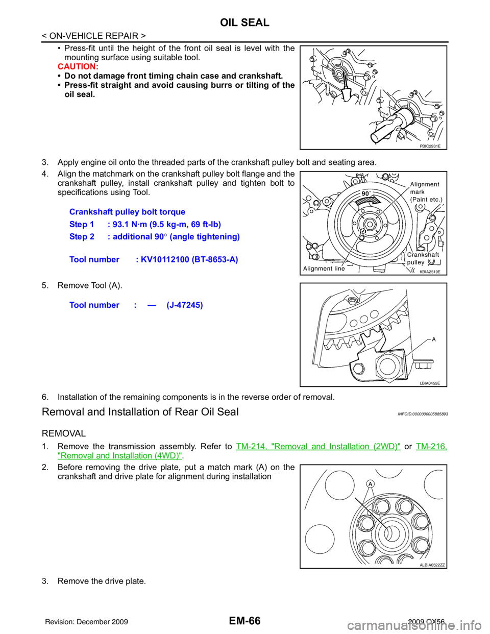
• Press-fit until the height of the front oil seal is level with themounting surface using suitable tool.
CAUTION:
• Do not damage front timing chain case and crankshaft.
• Press-fit straight and avoid cau sing burrs or tilting of the
oil seal.
3. Apply engine oil onto the threaded parts of the crankshaft pulley bolt and seating area.
4. Align the matchmark on the crankshaft pulley bolt flange and the crankshaft pulley, install crankshaft pulley and tighten bolt to
specifications using Tool.
5. Remove Tool (A).
6. Installation of the remaining components is in the reverse order of removal.
Removal and Installation of Rear Oil SealINFOID:0000000005885893
REMOVAL
1. Remove the transmission assembly. Refer to TM-214, "Removal and Installation (2WD)" or TM-216,
"Removal and Installation (4WD)".
2. Before removing the drive plate, put a match mark (A) on the crankshaft and drive plate for alignment during installation
3. Remove the drive plate.
PBIC2931E
Crankshaft pulley bolt torque
Step 1 : 93.1 N·m (9.5 kg-m, 69 ft-lb)
Step 2 : additional 90 ° (angle tightening)
Tool number : KV10112100 (BT-8653-A)
KBIA2519E
Tool number : — (J-47245)
LBIA0455E
ALBIA0522ZZ
Revision: December 20092009 QX56
Page 1892 of 4171
CYLINDER HEADEM-69
< ON-VEHICLE REPAIR >
C
DE
F
G H
I
J
K L
M A
EM
NP
O
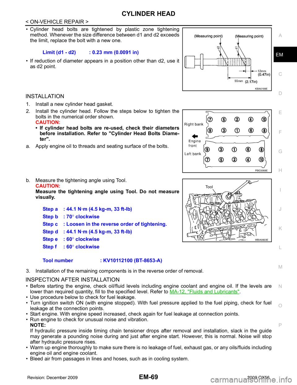
• Cylinder head bolts are tightened by plastic zone tightening
method. Whenever the size difference between d1 and d2 exceeds
the limit, replace the bolt with a new one.
• If reduction of diameter appears in a position other than d2, use it as d2 point.
INSTALLATION
1. Install a new cylinder head gasket.
2. Install the cylinder head. Follow the steps below to tighten the bolts in the numerical order shown.
CAUTION:
• If cylinder head bolts are re-used, check their diameters
before installation. Refer to "Cylinder Head Bolts Diame-
ter".
a. Apply engine oil to threads and seating surface of the bolts.
b. Measure the tightening angle using Tool. CAUTION:
Measure the tightening angl e using Tool. Do not measure
visually.
3. Installation of the remaining components is in the reverse order of removal.
INSPECTION AFTER INSTALLATION
• Before starting the engine, check oil/fluid levels including engine coolant and engine oil. If the levels are lower than required quantity, fill to the specified level. Refer to MA-12, "
Fluids and Lubricants".
• Use procedure below to check for fuel leakage.
• Turn ignition switch ON (with engine stopped). With fuel pressure applied to the fuel piping, check for fuel
leakage at the connection points.
• Start engine. With engine speed increased, check again for fuel leakage at connection points.
• Run engine to check for unusual noise and vibration.
NOTE:
If hydraulic pressure inside timing chain tensioner drops after removal and installation, slack in the guide
may generate a pounding noise during and just after engine start. However, this is normal. Noise will stop
after hydraulic pressure rises.
• Warm up engine thoroughly to make sure there is no leakage of fuel, exhaust gas, or any oils/fluids including
engine oil and engine coolant.
• Bleed air from passages in lines and hoses, such as in cooling system. Limit (d1 - d2) : 0.23 mm (0.0091 in)
KBIA0189E
PBIC0068E
Step a : 44.1 N·m (4.5 kg-m, 33 ft-lb)
Step b : 70°
clockwise
Step c : Loosen in the reverse order of tightening.
Step d : 44.1 N·m (4.5 kg-m, 33 ft-lb)
Step e : 60 ° clockwise
Step f : 60° clockwise
Tool number : KV10112100 (BT-8653-A)
WBIA0603E
Revision: December 20092009 QX56