2009 INFINITI QX56 100
[x] Cancel search: 100Page 1787 of 4171
![INFINITI QX56 2009 Factory Service Manual
EC-460
< ECU DIAGNOSIS >[VK56DE]
ECM
*1: 1st trip DTC No. is
the same as DTC No.
*2: This number is prescribed by SAE J2012.
*3: In Diagnostic Test Mode II (Self-diagnostic results), this number i INFINITI QX56 2009 Factory Service Manual
EC-460
< ECU DIAGNOSIS >[VK56DE]
ECM
*1: 1st trip DTC No. is
the same as DTC No.
*2: This number is prescribed by SAE J2012.
*3: In Diagnostic Test Mode II (Self-diagnostic results), this number i](/manual-img/42/57031/w960_57031-1786.png)
EC-460
< ECU DIAGNOSIS >[VK56DE]
ECM
*1: 1st trip DTC No. is
the same as DTC No.
*2: This number is prescribed by SAE J2012.
*3: In Diagnostic Test Mode II (Self-diagnostic results), this number is controlled by NISSAN.
*4: SRT code will not be set if the self-diagnostic result is NG.
*5: The troubleshooting for this DTC needs CONSULT-III.
*6: When the fail-safe operations for both self-diagnoses occur, the MIL illuminates.
*7: When the ECM is in the mode of displaying SRT status, MIL may flash. For the details, refer to "How to Display SRT Status".
*8: 2WD models
*9: Models with ICC
*10: Models without ICC
Emission-related Diagnostic InformationINFOID:0000000004114214
DTC AND 1ST TRIP DTC
The 1st trip DTC (whose number is the same as the DT C number) is displayed for the latest self-diagnostic
result obtained. If the ECM memory was cleared previous ly, and the 1st trip DTC did not reoccur, the 1st trip
DTC will not be displayed.
If a malfunction is detected during the 1st trip, the 1st trip DTC is stored in the ECM memory. The MIL will not
light up (two trip detection logic). If the same malfunc tion is not detected in the 2nd trip (meeting the required
driving pattern), the 1st trip DTC is cleared from the ECM memory. If the same malfunction is detected in the
2nd trip, both the 1st trip DTC and DTC are stored in t he ECM memory and the MIL lights up. In other words,
the DTC is stored in the ECM memory and the MIL light s up when the same malfunction occurs in two consec-
utive trips. If a 1st trip DTC is stored and a non-diagnostic operation is performed between the 1st and 2nd
trips, only the 1st trip DTC will continue to be stored. Fo r malfunctions that blink or light up the MIL during the
1st trip, the DTC and 1st trip DTC are stored in the ECM memory.
DIFFERENCE OF KEY P1615 1615 — 2 — SEC-30
INTERLOCK P1730 1730 — 1×TM-76
INPUT CLUTCH SOL P1752 1752 — 1 ×TM-80
FR BRAKE SOLENOID P1757 1757 — 1 ×TM-82
DRCT CLUTCH SOL P1762 1762 — 1 ×TM-84
HLR CLUTCH SOLENOID P1767 1767 — 1 ×TM-86
L C BRAKE SOLENOID P1772 1772 — 1 ×TM-88
L C BRAKE SOLENOID P1774 1774 — 1 ×TM-90
BRAKE SW/CIRCUIT P1805 1805 — 2 — EC-348
ETC MOT PWR-B1 P2100 2100 — 1×EC-351
ETC FUNCTION/CIRC-B1 P2101 2101 — 1 ×EC-354
ETC MOT PWR P2103 2103 — 1 ×EC-351
ETC MOT-B1 P2118 2118 — 1 ×EC-358
ETC ACTR-B1 P2119 2119 — 1 ×EC-360
APP SEN 1/CIRC P2122 2122 — 1 ×EC-362
APP SEN 1/CIRC P2123 2123 — 1 ×EC-362
APP SEN 2/CIRC P2127 2127 — 1 ×EC-365
APP SEN 2/CIRC P2128 2128 — 1 ×EC-365
TP SENSOR-B1 P2135 2135 — 1 ×EC-369
APP SENSOR P2138 2138 — 1 ×EC-373
A/F SENSOR1 (B1) P2A00 2A00 — 2 ×EC-377
A/F SENSOR1 (B2) P2A03 2A03 — 2 ×EC-377
Items
(CONSULT-IIl screen terms) DTC*
1
SRT code Trip MIL
Reference
page
CONSULT-IIl
GST*
2ECM*3
Revision: December 20092009 QX56
Page 1799 of 4171
![INFINITI QX56 2009 Factory Service Manual
EC-472
< ECU DIAGNOSIS >[VK56DE]
ECM
MISFIRE A1H Multiple Cylinder MisfiresP0301 80H 24H
Misfiring counter at 1000 revolution of
the first cylinder
P0302 81H 24H Misfiring counter at 1000 revolution INFINITI QX56 2009 Factory Service Manual
EC-472
< ECU DIAGNOSIS >[VK56DE]
ECM
MISFIRE A1H Multiple Cylinder MisfiresP0301 80H 24H
Misfiring counter at 1000 revolution of
the first cylinder
P0302 81H 24H Misfiring counter at 1000 revolution](/manual-img/42/57031/w960_57031-1798.png)
EC-472
< ECU DIAGNOSIS >[VK56DE]
ECM
MISFIRE A1H Multiple Cylinder MisfiresP0301 80H 24H
Misfiring counter at 1000 revolution of
the first cylinder
P0302 81H 24H Misfiring counter at 1000 revolution of
the second cylinder
P0303 82H 24H Misfiring counter at 1000 revolution of
the third cylinder
P0304 83H 24H Misfiring counter at 1000 revolution of
the fourth cylinder
P0305 84H 24H Misfiring counter at 1000 revolution of
the fifth cylinder
P0306 85H 24H Misfiring counter at 1000 revolution of
the sixth cylinder
P0307 86H 24H Misfiring counter at 1000 revolution of
the seventh cylinder
P0308 87H 24H Misfiring counter at 1000 revolution of
the eighth cylinder
P0300 88H 24H Misfiring counter at 1000 revolution of
the multiple cylinders
P0301 89H 24H Misfiring counter at 200 revolution of the
first cylinder
P0302 8AH 24H Misfiring counter at 200 revolution of the
second cylinder
P0303 8BH 24H Misfiring counter at 200 revolution of the
third cylinder
P0304 8CH 24H Misfiring counter at 200 revolution of the
fourth cylinder
P0305 8DH 24H Misfiring counter at 200 revolution of the
fifth cylinder
P0306 8EH 24H Misfiring counter at 200 revolution of the
sixth cylinder
P0307 8FH 24H Misfiring counter at 200 revolution of the
seventh cylinder
P0308 90H 24H Misfiring counter at 200 revolution of the
eighth cylinder
P0300 91H 24H Misfiring counter at 1000 revolution of
the single cylinder
P0300 92H 24H Misfiring counter at 200 revolution of the
single cylinder
P0300 93H 24H Misfiring counter at 200 revolution of the
multiple cylinders
Item
OBD-
MID Self-diagnostic test item DTC Test value and Test
limit
(GST display) Description
TID Unit and
Scaling ID
Revision: December 20092009 QX56
Page 1803 of 4171
![INFINITI QX56 2009 Factory Service Manual
EC-476
< SYMPTOM DIAGNOSIS >[VK56DE]
ENGINE CONTROL SYSTEM SYMPTOMS
1 - 6: The numbers refer to the order of inspection.
(continued on next page)
SYSTEM — ENGINE MECHANICAL & OTHER
Mass air flow se INFINITI QX56 2009 Factory Service Manual
EC-476
< SYMPTOM DIAGNOSIS >[VK56DE]
ENGINE CONTROL SYSTEM SYMPTOMS
1 - 6: The numbers refer to the order of inspection.
(continued on next page)
SYSTEM — ENGINE MECHANICAL & OTHER
Mass air flow se](/manual-img/42/57031/w960_57031-1802.png)
EC-476
< SYMPTOM DIAGNOSIS >[VK56DE]
ENGINE CONTROL SYSTEM SYMPTOMS
1 - 6: The numbers refer to the order of inspection.
(continued on next page)
SYSTEM — ENGINE MECHANICAL & OTHER
Mass air flow sensor circuit
1
12 2
222 2 EC-103,
EC-109
Engine coolant temperature sensor circuit
333
EC-120,
EC-128
Air fuel ratio (A/F ) sensor 1 circuit EC-136
,
EC-140
,
EC-143
,
EC-146
,
EC-377
Throttle position sensor circuit 22EC-124
,
EC-185
,
EC-302
,
EC-304
,
EC-369
Accelerator pedal position sensor circuit 3 2 1 EC-280
,
EC-362
,
EC-365
,
EC-373
Knock sensor circuit 2 3 EC-195
Crankshaft position sensor (POS) circuit 2 2EC-198
Camshaft position sensor (PHASE) circuit 3 2 EC-202
Vehicle speed signal circuit 2 3 3 3 EC-271
Power steering pressure sensor circuit 2 3 3 EC-277
ECM 22333333333 EC-280,
EC-282
Intake valve timing control solenoid valve cir-
cuit 32 13223 3
EC-100
Transmission range signal circuit 3 3 3 3 3 EC-288
Refrigerant pressure sensor circuit 2 3 3 4EC-416
Electrical load signal circuit 3EC-390
Air conditioner circuit 223333333 3 2HAC-25
ABS actuator and electric unit (control unit) 4 BRC-37
SYMPTOM
Refer-
ence page
HARD/NO START/RESTART (EXCP. HA)
ENGINE STALL
HESITATION/SURGING/FLAT SPOT
SPARK KNOCK/DETONATION
LACK OF POWER/POOR ACCELERATION
HIGH IDLE/LOW IDLE
ROUGH IDLE/HUNTING
IDLING VIBRATION
SLOW/NO RETURN TO IDLE
OVERHEATS/WATER TEMPERATURE HIGH
EXCESSIVE FUEL CONSUMPTION
EXCESSIVE OIL CONSUMPTION
BATTERY DEAD (UNDER CHARGE)
Warranty symptom code AA AB AC AD AE AF AG AH AJ AK AL AM HA
Revision: December 20092009 QX56
Page 1811 of 4171
![INFINITI QX56 2009 Factory Service Manual
EC-484
< PREPARATION >[VK56DE]
PREPARATION
PREPARATION
PREPARATION
Special Service ToolINFOID:0000000003771744
The actual shapes of Kent-Moore tool
s may differ from those of special service tools il INFINITI QX56 2009 Factory Service Manual
EC-484
< PREPARATION >[VK56DE]
PREPARATION
PREPARATION
PREPARATION
Special Service ToolINFOID:0000000003771744
The actual shapes of Kent-Moore tool
s may differ from those of special service tools il](/manual-img/42/57031/w960_57031-1810.png)
EC-484
< PREPARATION >[VK56DE]
PREPARATION
PREPARATION
PREPARATION
Special Service ToolINFOID:0000000003771744
The actual shapes of Kent-Moore tool
s may differ from those of special service tools illustrated here.
Tool number
(Kent-Moore No.)
Tool nameDescription
EG17650301
(J-33984-A)
Radiator cap tester
adapter Adapting radiator cap tester to radiator cap and ra-
diator filler neck
a: 28 (1.10) dia.
b: 31.4 (1.236) dia.
c: 41.3 (1.626) dia.
Unit: mm (in)
KV10117100
(J-36471-A)
Heated oxygen sensor
wrench Loosening or tightening heated oxygen sensors
with 22 mm (0.87 in) hexagon nut
KV10114400
(J-38365)
Heated oxygen sensor
wrench Loosening or tightening heated oxygen sensors
a: 22 mm (0.87 in)
(J-44626)
Air fuel ratio (A/F) sen-
sor wrench Loosening or tightening air fuel ratio (A/F) sensor 1
(J-44321)
Fuel pressure gauge
kit Checking fuel pressure
(J-44321-6)
Fuel pressure adapter Connecting fuel pressure gauge to quick connec-
tor type fuel lines.
S-NT564
S-NT379
S-NT636
LEM054
LEC642
LBIA0376E
Revision: December 20092009 QX56
Page 1827 of 4171

EM-4
< PRECAUTION >
PRECAUTIONS
5. When the repair work is completed, return the ignition switch to the ″LOCK ″ position before connecting
the battery cables. (At this time, the steering lock mechanism will engage.)
6. Perform a self-diagnosis check of a ll control units using CONSULT-III.
Precaution for Drain Engine CoolantINFOID:0000000005885850
Drain engine coolant when engine is cooled.
Precaution for Disconnecting Fuel PipingINFOID:0000000005885851
• Before starting work, make sure no fire or spark producing items are in the work area.
• Release fuel pressure before disconnecting and disassembly.
• After disconnecting pipes, plug openings to stop fuel leakage.
Precaution for Removal and DisassemblyINFOID:0000000005885852
• When instructed to use special service tools, use the s pecified tools. Always be careful to work safely, avoid
forceful or uninstructed operations.
• Exercise maximum care to avoid damage to mating or sliding surfaces.
• Cover openings of engine system with tape or the equivalent, if necessary, to seal out foreign materials.
• Mark and arrange disassembly parts in an organi zed way for easy troubleshooting and assembly.
• When loosening nuts and bolts, as a basic rule, start with the one furthest outside, then the one diagonally opposite, and so on. If the order of loosening is specified, do exactly as specified. Power tools may be used
where noted in the step.
Precaution for Inspection, Repair and ReplacementINFOID:0000000005885853
Before repairing or replacing, thoroughly inspect parts. Inspect new replacement parts in the same way, and
replace if necessary.
Precaution for Assembly and InstallationINFOID:0000000005885854
• Use torque wrench to tighten bolts or nuts to specification.
• When tightening nuts and bolts, as a basic rule, equally tighten in several different steps starting with theones in center, then ones on inside and outside diagonally in this order. If the order of tightening is specified,
do exactly as specified.
• Replace with new gasket, packing, oil seal or O-ring.
• Thoroughly wash, clean, and air-blow each part. Carefully check engine oil or engine coolant passages for any restriction and blockage.
• Avoid damaging sliding or mating surfaces. Completely remove foreign materials such as cloth lint or dust. Before assembly, oil sliding surfaces well.
• Release air within route when refilling after draining engine coolant.
• Before starting engine, apply fuel pressure to fuel lines with turning ignition switch ON (with engine stopped). Then make sure that there are no leaks at fuel line connections.
• After repairing, start engine and increase engine s peed to check engine coolant, fuel, oil, and exhaust sys-
tems for leakage.
Parts Requiring Angular TighteningINFOID:0000000005885855
• For final tightening of the following engine parts use Tool:
- Cylinder head bolts
- Main bearing cap bolts
- Connecting rod cap bolts
- Crankshaft pulley bolt (No angle wrench is required as the bolt flange is provided with notches for angle tightening)
• Do not use a torque value for final tightening.
• The torque value for these parts are for a preliminary step.
• Ensure thread and seat surfaces are clean and lightly coated with engine oil. Tool number : KV10112100 (BT-8653-A)
Revision: December 20092009 QX56
Page 1828 of 4171

PRECAUTIONSEM-5
< PRECAUTION >
C
DE
F
G H
I
J
K L
M A
EM
NP
O
Precaution for Liquid GasketINFOID:0000000005885856
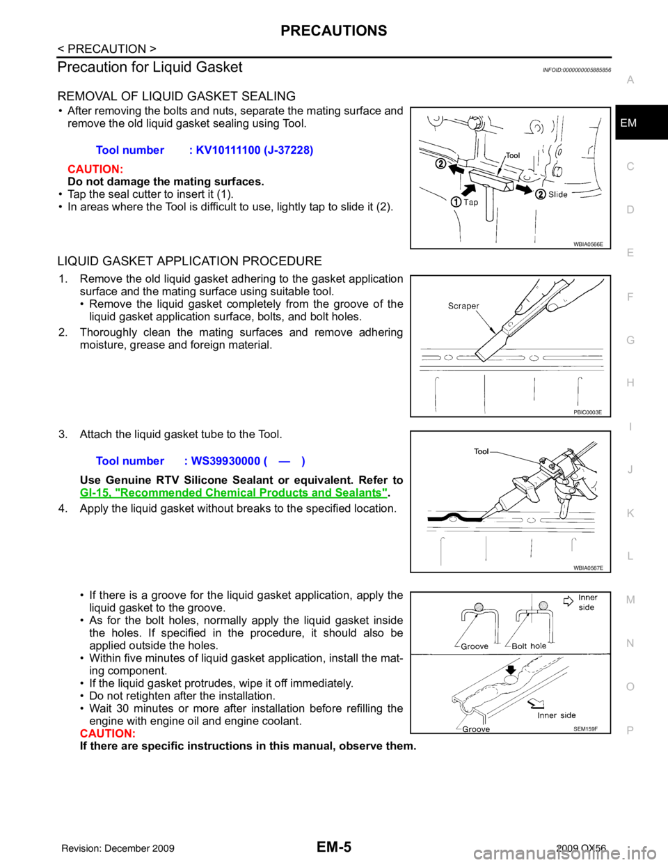
REMOVAL OF LIQUID GASKET SEALING
• After removing the bolts and nuts, separate the mating surface and
remove the old liquid gasket sealing using Tool.
CAUTION:
Do not damage the mating surfaces.
• Tap the seal cutter to insert it (1).
• In areas where the Tool is difficult to use, lightly tap to slide it (2).
LIQUID GASKET APPLICATION PROCEDURE
1. Remove the old liquid gasket adhering to the gasket application surface and the mating surface using suitable tool.
• Remove the liquid gasket completely from the groove of the
liquid gasket application surface, bolts, and bolt holes.
2. Thoroughly clean the mating surfaces and remove adhering moisture, grease and foreign material.
3. Attach the liquid gasket tube to the Tool. Use Genuine RTV Silicone Sealant or equivalent. Refer to
GI-15, "
Recommended Chemical Products and Sealants".
4. Apply the liquid gasket without breaks to the specified location.
• If there is a groove for the liquid gasket application, apply theliquid gasket to the groove.
• As for the bolt holes, normally apply the liquid gasket inside
the holes. If specified in the procedure, it should also be
applied outside the holes.
• Within five minutes of liquid gasket application, install the mat-
ing component.
• If the liquid gasket protrudes, wipe it off immediately.
• Do not retighten after the installation.
• Wait 30 minutes or more after installation before refilling the engine with engine oil and engine coolant.
CAUTION:
If there are specific instructions in this manual, observe them.
Tool number : KV10111100 (J-37228)
WBIA0566E
PBIC0003E
Tool number : WS39930000 ( — )
WBIA0567E
SEM159F
Revision: December 20092009 QX56
Page 1829 of 4171

EM-6
< PREPARATION >
PREPARATION
PREPARATION
PREPARATION
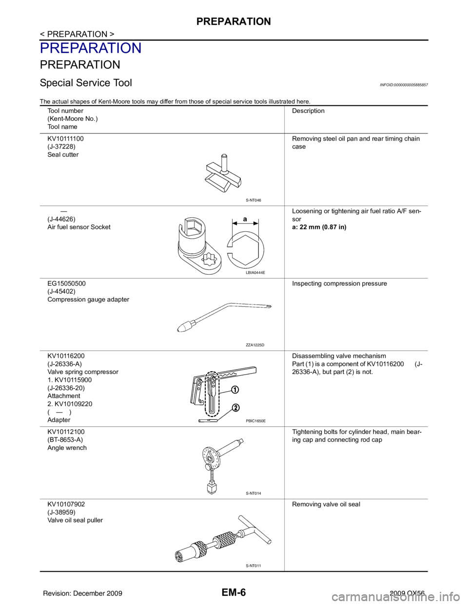
Special Service ToolINFOID:0000000005885857
The actual shapes of Kent-Moore tools may differ from those of special service tools illustrated here.
Tool number
(Kent-Moore No.)
Tool name Description
K V 1 0 1111 0 0
(J-37228)
Seal cutter Removing steel oil pan and rear timing chain
case
—
(J-44626)
Air fuel sensor Socket Loosening or tightening air fuel ratio A/F sen-
sor
a: 22 mm (0.87 in)
EG15050500
(J-45402)
Compression gauge adapter Inspecting compression pressure
KV10116200
(J-26336-A)
Valve spring compressor
1. KV10115900
(J-26336-20)
Attachment
2. KV10109220
(—)
Adapter Disassembling valve mechanism
Part (1) is a component of KV10116200 (J-
26336-A), but part (2) is not.
KV10112100
(BT-8653-A)
Angle wrench Tightening bolts for cylinder head, main bear-
ing cap and connecting rod cap
KV10107902
(J-38959)
Valve oil seal puller Removing valve oil seal
S-NT046
LBIA0444E
ZZA1225D
PBIC1650E
S-NT014
S-NT011
Revision: December 20092009 QX56
Page 1830 of 4171

PREPARATIONEM-7
< PREPARATION >
C
DE
F
G H
I
J
K L
M A
EM
NP
O
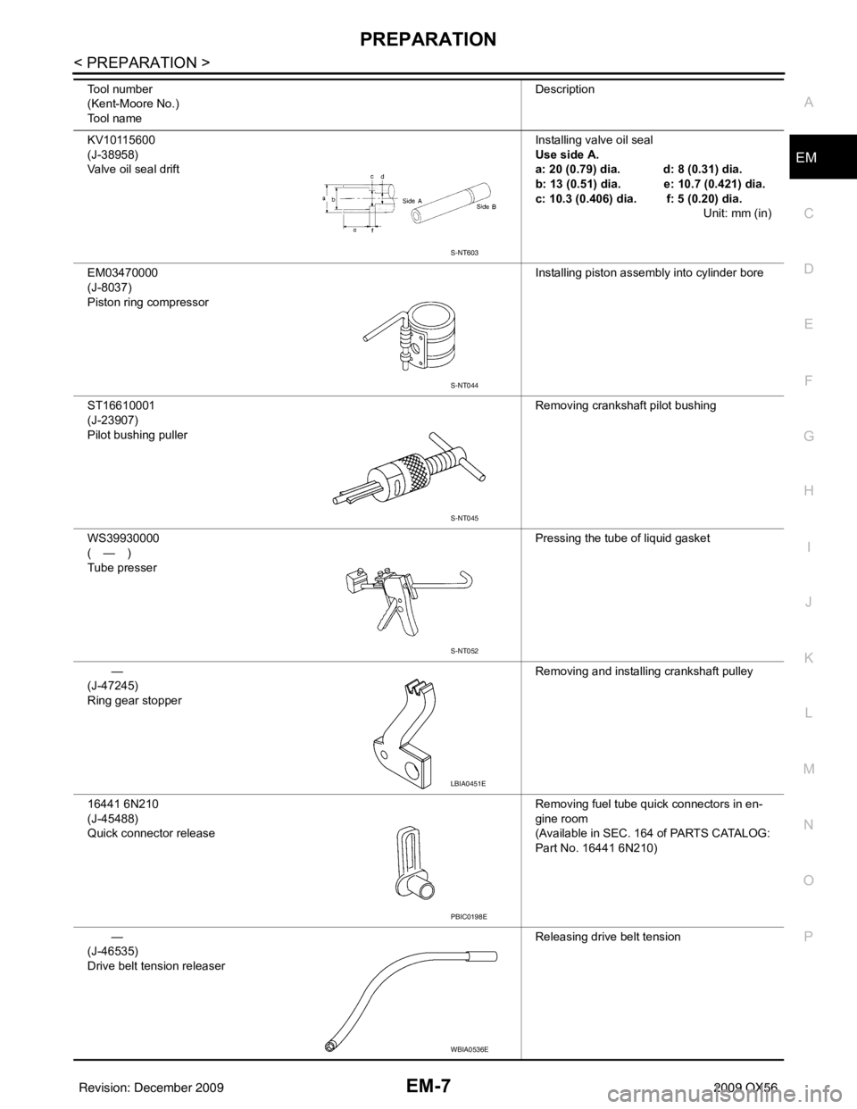
KV10115600
(J-38958)
Valve oil seal drift
Installing valve oil seal
Use side A.
a: 20 (0.79) dia. d: 8 (0.31) dia.
b: 13 (0.51) dia. e: 10.7 (0.421) dia.
c: 10.3 (0.406) dia. f: 5 (0.20) dia.
Unit: mm (in)
EM03470000
(J-8037)
Piston ring compressor Installing piston assembly into cylinder bore
ST16610001
(J-23907)
Pilot bushing puller Removing crankshaft pilot bushing
WS39930000
(—)
Tube presser Pressing the tube of liquid gasket
—
(J-47245)
Ring gear stopper Removing and installing crankshaft pulley
16441 6N210
(J-45488)
Quick connector release Removing fuel tube quick connectors in en-
gine room
(Available in SEC. 164 of PARTS CATALOG:
Part No. 16441 6N210)
—
(J-46535)
Drive belt tension releaser Releasing drive belt tension
Tool number
(Kent-Moore No.)
Tool name
Description
S-NT603
S-NT044
S-NT045
S-NT052
LBIA0451E
PBIC0198E
WBIA0536E
Revision: December 20092009 QX56