2009 CHERY TIGGO power steering
[x] Cancel search: power steeringPage 1392 of 1903

Downloaded from www.Manualslib.com manuals search engine 2. Remove the hose clamps (1) securing the returnhose and the supply hose to the steering fluid res-
ervoir fitting.
3. Slide the hose off the end of the reservoir fitting and remove the steering fluid reservoir.
4. Installation is in the reverse order of removal.
Installation Notes:
• Fill the power steering reservoir to the proper level.
• Check the system for leaks.
Power Steering Pressure and Return Lines - 1.6L & 1.8L & 2.0L
Removal & Installation
1. Siphon as much steering fluid as possible from the power steering fluid reservoir.
2. Remove the engine cover.
3. Remove the hose clamps securing the return hose and the supply hose to the steering fluid reservoir fitting.
4. Remove the high pressure (1) and low pressure
lines (2) from the power steering pump (drain
steering fluid from lines).
(Tighten: High pressure line to power steering
pump 40 - 50 N·m)
(Tighten: Low pressure line to power steering pump
40 - 50 N·m)
ON-VEHICLE SERVICE
LTSM110038
LTSM110039
BESM110011
11
11 –37Chery Automobile Co., Ltd.
Page 1393 of 1903
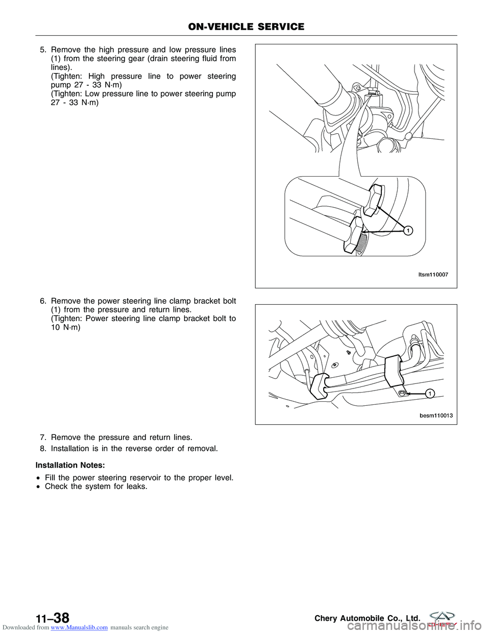
Downloaded from www.Manualslib.com manuals search engine 5. Remove the high pressure and low pressure lines(1) from the steering gear (drain steering fluid from
lines).
(Tighten: High pressure line to power steering
pump 27 - 33 N·m)
(Tighten: Low pressure line to power steering pump
27 - 33 N·m)
6. Remove the power steering line clamp bracket bolt (1) from the pressure and return lines.
(Tighten: Power steering line clamp bracket bolt to
10 N·m)
7. Remove the pressure and return lines.
8. Installation is in the reverse order of removal.
Installation Notes:
• Fill the power steering reservoir to the proper level.
• Check the system for leaks.
ON-VEHICLE SERVICE
LTSM110007
BESM110013
11 –38Chery Automobile Co., Ltd.
Page 1394 of 1903
Downloaded from www.Manualslib.com manuals search engine Power Steering Pressure and Return Lines - 2.4L
Removal & Installation
1. Siphon as much steering fluid as possible from the power steering fluid reservoir.
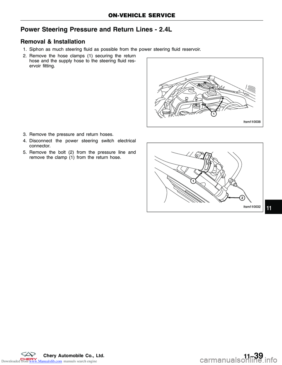
2. Remove the hose clamps (1) securing the returnhose and the supply hose to the steering fluid res-
ervoir fitting.
3. Remove the pressure and return hoses.
4. Disconnect the power steering switch electrical connector.
5. Remove the bolt (2) from the pressure line and remove the clamp (1) from the return hose.
ON-VEHICLE SERVICE
LTSM110038
LTSM110032
11
11 –39Chery Automobile Co., Ltd.
Page 1395 of 1903
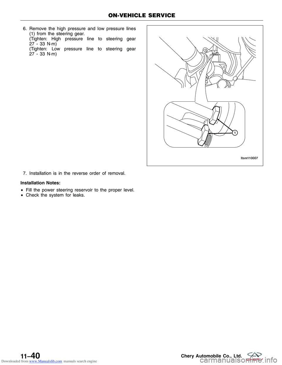
Downloaded from www.Manualslib.com manuals search engine 6. Remove the high pressure and low pressure lines(1) from the steering gear.
(Tighten: High pressure line to steering gear
27 - 33 N·m)
(Tighten: Low pressure line to steering gear
27 - 33 N·m)
7. Installation is in the reverse order of removal.
Installation Notes:
• Fill the power steering reservoir to the proper level.
• Check the system for leaks.
ON-VEHICLE SERVICE
LTSM110007
11 –40Chery Automobile Co., Ltd.
Page 1875 of 1903
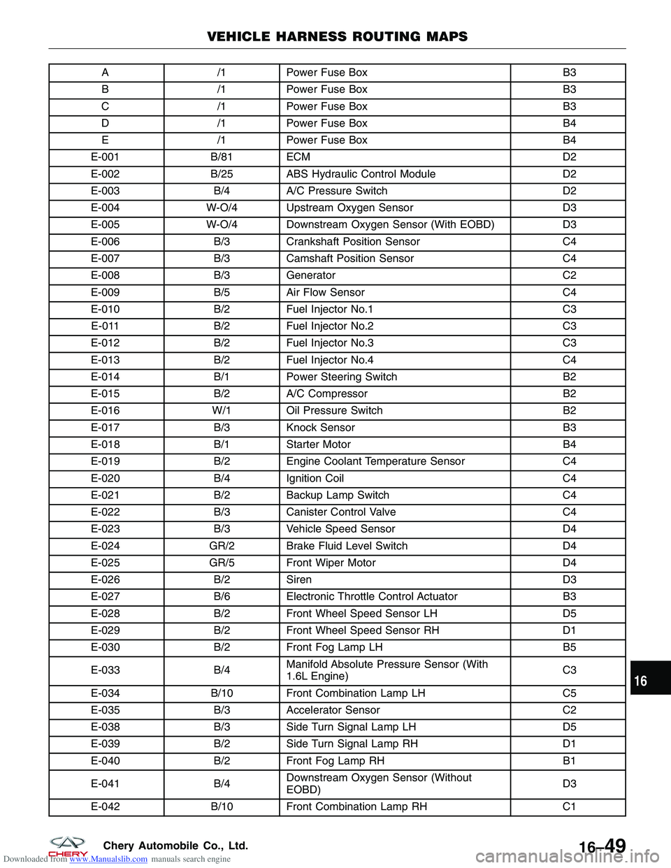
Downloaded from www.Manualslib.com manuals search engine A/1Power Fuse Box B3
B /1Power Fuse Box B3
C /1Power Fuse Box B3
D /1Power Fuse Box B4
E /1Power Fuse Box B4
E-001 B/81 ECM D2
E-002 B/25 ABS Hydraulic Control Module D2
E-003 B/4A/C Pressure Switch D2
E-004 W-O/4 Upstream Oxygen Sensor D3
E-005 W-O/4 Downstream Oxygen Sensor (With EOBD) D3
E-006 B/3Crankshaft Position Sensor C4
E-007 B/3Camshaft Position Sensor C4
E-008 B/3Generator C2
E-009 B/5Air Flow Sensor C4
E-010 B/2Fuel Injector No.1 C3
E-011 B/2Fuel Injector No.2 C3
E-012 B/2Fuel Injector No.3 C3
E-013 B/2Fuel Injector No.4 C4
E-014 B/1Power Steering Switch B2
E-015 B/2A/C Compressor B2
E-016 W/1 Oil Pressure Switch B2
E-017 B/3Knock Sensor B3
E-018 B/1Starter Motor B4
E-019 B/2Engine Coolant Temperature Sensor C4
E-020 B/4Ignition Coil C4
E-021 B/2Backup Lamp Switch C4
E-022 B/3Canister Control Valve C4
E-023 B/3Vehicle Speed Sensor D4
E-024 GR/2 Brake Fluid Level Switch D4
E-025 GR/5 Front Wiper Motor D4
E-026 B/2Siren D3
E-027 B/6Electronic Throttle Control Actuator B3
E-028 B/2Front Wheel Speed Sensor LH D5
E-029 B/2Front Wheel Speed Sensor RH D1
E-030 B/2Front Fog Lamp LH B5
E-033 B/4Manifold Absolute Pressure Sensor (With
1.6L Engine) C3
E-034 B/10 Front Combination Lamp LH C5
E-035 B/3Accelerator Sensor C2
E-038 B/3Side Turn Signal Lamp LH D5
E-039 B/2Side Turn Signal Lamp RH D1
E-040 B/2Front Fog Lamp RH B1
E-041 B/4Downstream Oxygen Sensor (Without
EOBD) D3
E-042 B/10 Front Combination Lamp RH C1
VEHICLE HARNESS ROUTING MAPS
16
16–49Chery Automobile Co., Ltd.
Page 1878 of 1903
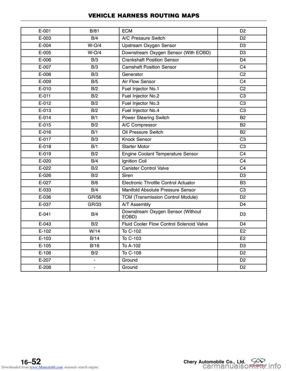
Downloaded from www.Manualslib.com manuals search engine E-001B/81 ECM D2
E-003 B/4A/C Pressure Switch D2
E-004 W-O/4 Upstream Oxygen Sensor D3
E-005 W-O/4 Downstream Oxygen Sensor (With EOBD) D3
E-006 B/3Crankshaft Position Sensor D4
E-007 B/3Camshaft Position Sensor C4
E-008 B/3Generator C2
E-009 B/5Air Flow Sensor C4
E-010 B/2Fuel Injector No.1 C2
E-011 B/2Fuel Injector No.2 C3
E-012 B/2Fuel Injector No.3 C3
E-013 B/2Fuel Injector No.4 C3
E-014 B/1Power Steering Switch B2
E-015 B/2A/C Compressor B2
E-016 B/1Oil Pressure Switch B2
E-017 B/3Knock Sensor C3
E-018 B/1Starter Motor C3
E-019 B/2Engine Coolant Temperature Sensor C4
E-020 B/4Ignition Coil C4
E-022 B/2Canister Control Valve C4
E-026 B/2Siren D3
E-027 B/6Electronic Throttle Control Actuator B3
E-033 B/4Manifold Absolute Pressure Sensor C3
E-036 GR/56 TCM (Transmission Control Module) D2
E-037 GR/33 A/T Assembly D4
E-041 B/4Downstream Oxygen Sensor (Without
EOBD) D3
E-043 B/2Fluid Cooler Flow Control Solenoid Valve D4
E-102 W/14 To C-102 E2
E-103 B/14 To C-103 E2
E-105 B/16 To A-102 D3
E-108 B/2To C-108 D2
E-207 -Ground D2
E-208 -Ground D2
VEHICLE HARNESS ROUTING MAPS
16–52Chery Automobile Co., Ltd.
Page 1882 of 1903
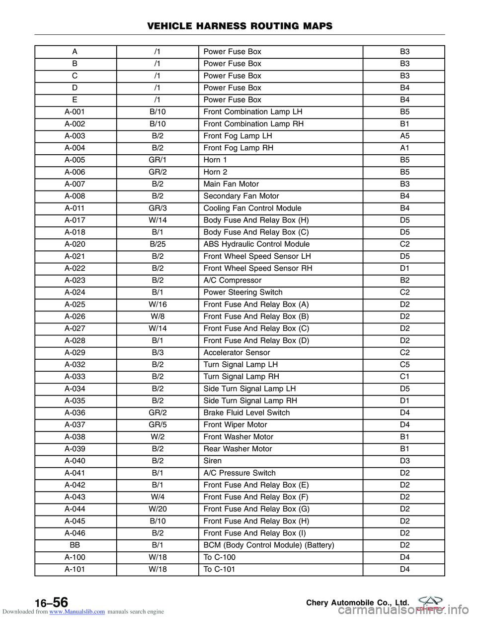
Downloaded from www.Manualslib.com manuals search engine A/1Power Fuse Box B3
B /1Power Fuse Box B3
C /1Power Fuse Box B3
D /1Power Fuse Box B4
E /1Power Fuse Box B4
A-001 B/10 Front Combination Lamp LH B5
A-002 B/10 Front Combination Lamp RH B1
A-003 B/2Front Fog Lamp LH A5
A-004 B/2Front Fog Lamp RH A1
A-005 GR/1 Horn 1 B5
A-006 GR/2 Horn 2 B5
A-007 B/2Main Fan Motor B3
A-008 B/2Secondary Fan Motor B4
A-011 GR/3 Cooling Fan Control Module B4
A-017 W/14 Body Fuse And Relay Box (H) D5
A-018 B/1Body Fuse And Relay Box (C) D5
A-020 B/25 ABS Hydraulic Control Module C2
A-021 B/2Front Wheel Speed Sensor LH D5
A-022 B/2Front Wheel Speed Sensor RH D1
A-023 B/2A/C Compressor B2
A-024 B/1Power Steering Switch C2
A-025 W/16 Front Fuse And Relay Box (A) D2
A-026 W/8 Front Fuse And Relay Box (B) D2
A-027 W/14 Front Fuse And Relay Box (C) D2
A-028 B/1Front Fuse And Relay Box (D) D2
A-029 B/3Accelerator Sensor C2
A-032 B/2Turn Signal Lamp LH C5
A-033 B/2Turn Signal Lamp RH C1
A-034 B/2Side Turn Signal Lamp LH D5
A-035 B/2Side Turn Signal Lamp RH D1
A-036 GR/2 Brake Fluid Level Switch D4
A-037 GR/5 Front Wiper Motor D4
A-038 W/2 Front Washer Motor B1
A-039 B/2Rear Washer Motor B1
A-040 B/2Siren D3
A-041 B/1A/C Pressure Switch D2
A-042 B/1Front Fuse And Relay Box (E) D2
A-043 W/4 Front Fuse And Relay Box (F) D2
A-044 W/20 Front Fuse And Relay Box (G) D2
A-045 B/10 Front Fuse And Relay Box (H) D2
A-046 B/2Front Fuse And Relay Box (I) D2
BB B/1BCM (Body Control Module) (Battery) D2
A-100 W/18 To C-100 D4
A-101 W/18 To C-101 D4
VEHICLE HARNESS ROUTING MAPS
16–56Chery Automobile Co., Ltd.
Page 1897 of 1903
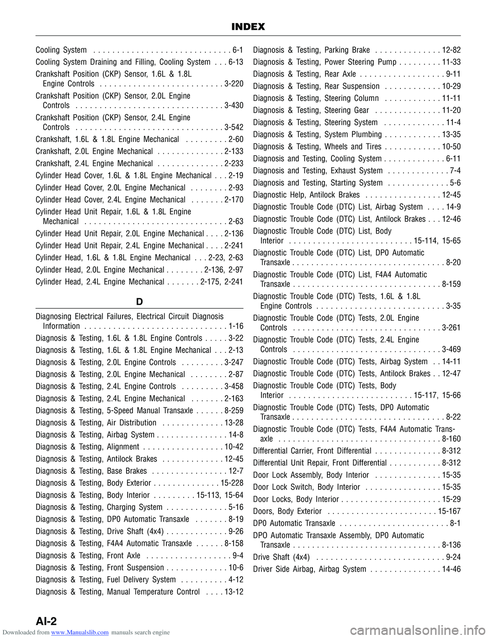
Downloaded from www.Manualslib.com manuals search engine Cooling System.............................6-1
Cooling System Draining and Filling, Cooling System . . . 6-13
Crankshaft Position (CKP) Sensor, 1.6L & 1.8L Engine Controls .......................... 3-220
Crankshaft Position (CKP) Sensor, 2.0L Engine Controls ............................... 3-430
Crankshaft Position (CKP) Sensor, 2.4L Engine Controls ............................... 3-542
Crankshaft, 1.6L & 1.8L Engine Mechanical .........2-60
Crankshaft, 2.0L Engine Mechanical ..............2-133
Crankshaft, 2.4L Engine Mechanical ..............2-233
Cylinder Head Cover, 1.6L & 1.8L Engine Mechanical . . . 2-19
Cylinder Head Cover, 2.0L Engine Mechanical ........2-93
Cylinder Head Cover, 2.4L Engine Mechanical .......2-170
Cylinder Head Unit Repair, 1.6L & 1.8L Engine Mechanical .............................. 2-63
Cylinder Head Unit Repair, 2.0L Engine Mechanical ....2-136
Cylinder Head Unit Repair, 2.4L Engine Mechanical ....2-241
Cylinder Head, 1.6L & 1.8L Engine Mechanical . . . 2-23, 2-63
Cylinder Head, 2.0L Engine Mechanical ........2-136, 2-97
Cylinder Head, 2.4L Engine Mechanical .......2-175, 2-241
D
Diagnosing Electrical Failures, Electrical Circuit Diagnosis
Information .............................. 1-16
Diagnosis & Testing, 1.6L & 1.8L Engine Controls .....3-22
Diagnosis & Testing, 1.6L & 1.8L Engine Mechanical . . . 2-13
Diagnosis & Testing, 2.0L Engine Controls .........3-247
Diagnosis & Testing, 2.0L Engine Mechanical ........2-87
Diagnosis & Testing, 2.4L Engine Controls .........3-458
Diagnosis & Testing, 2.4L Engine Mechanical .......2-163
Diagnosis & Testing, 5-Speed Manual Transaxle ......8-259
Diagnosis & Testing, Air Distribution .............13-28
Diagnosis & Testing, Airbag System ...............14-8
Diagnosis & Testing, Alignment .................10-42
Diagnosis & Testing, Antilock Brakes .............12-45
Diagnosis & Testing, Base Brakes ................12-7
Diagnosis & Testing, Body Exterior ..............15-228
Diagnosis & Testing, Body Interior .........15-113, 15-64
Diagnosis & Testing, Charging System .............5-16
Diagnosis & Testing, DP0 Automatic Transaxle .......8-19
Diagnosis & Testing, Drive Shaft (4x4) .............9-26
Diagnosis & Testing, F4A4 Automatic Transaxle ......8-158
Diagnosis & Testing, Front Axle ..................9-4
Diagnosis & Testing, Front Suspension .............10-6
Diagnosis & Testing, Fuel Delivery System ..........4-12
Diagnosis & Testing, Manual Temperature Control ....13-12 Diagnosis & Testing, Parking Brake
..............12-82
Diagnosis & Testing, Power Steering Pump .........11-33
Diagnosis & Testing, Rear Axle ..................9-11
Diagnosis & Testing, Rear Suspension ............10-29
Diagnosis & Testing, Steering Column ............11-11
Diagnosis & Testing, Steering Gear ..............11-20
Diagnosis & Testing, Steering System .............11-4
Diagnosis & Testing, System Plumbing ............13-35
Diagnosis & Testing, Wheels and Tires ............10-50
Diagnosis and Testing, Cooling System .............6-11
Diagnosis and Testing, Exhaust System .............7-4
Diagnosis and Testing, Starting System .............5-6
Diagnostic Help, Antilock Brakes ................12-45
Diagnostic Trouble Code (DTC) List, Airbag System ....14-9
Diagnostic Trouble Code (DTC)
List, Antilock Brakes . . . 12-46
Diagnostic Trouble Code (DTC) List, Body Interior .......................... 15-114, 15-65
Diagnostic Trouble Code (DTC) List, DP0 Automatic Transaxle ................................ 8-20
Diagnostic Trouble Code (DTC) List, F4A4 Automatic Transaxle ............................... 8-159
Diagnostic Trouble Code (DTC) Tests, 1.6L & 1.8L Engine Controls ........................... 3-35
Diagnostic Trouble Code (DTC) Tests, 2.0L Engine Controls ............................... 3-261
Diagnostic Trouble Code (DTC) Tests, 2.4L Engine Controls ............................... 3-469
Diagnostic Trouble Code (DTC) Tests, Airbag System . . 14-11
Diagnostic Trouble Code (DTC) Tests, Antilock Brakes . . 12-47
Diagnostic Trouble Code (DTC) Tests, Body Interior .......................... 15-117, 15-66
Diagnostic Trouble Code (DTC) Tests, DP0 Automatic Transaxle ................................ 8-22
Diagnostic Trouble Code (DTC) Tests, F4A4 Automatic Trans- axle .................................. 8-160
Differential Carrier, Front Differential ..............8-312
Differential Unit Repair, Front Differential ...........8-312
Door Lock Assembly, Body Interior ..............15-35
Door Lock Switch, Body Interior ................15-35
Door Locks, Body Interior ..................... 15-29
Doors, Body Exterior ....................... 15-167
DP0 Automatic Transaxle .......................8-1
DPO Automatic Transaxle Assembly, DP0 Automatic Transaxle ............................... 8-136
Drive Shaft (4x4) ........................... 9-24
Driver Side Airbag, Airbag System ...............14-46
INDEX
AI-2