Page 513 of 1903

Downloaded from www.Manualslib.com manuals search engine GENERAL INFORMATION
Description
The Engine Control Module (ECM) utilizes integrated circuitry and information carried on the Controller Area Network
(CAN) data bus along with many hard wired inputs to monitor many sensors and switches inputs throughout the
vehicle. In response to those inputs, the internal circuitry and programming of the ECM allow it to control and inte-
grate many electronic functions and features of the vehicle through both hard wired outputs and the transmission of
electronic message outputs to other electronic modules in the vehicle over the CAN data bus.
The following are the input and output components monitored by the ECM. The monitored functions include compo-
nents from the engine, ignition, transaxle, air conditioning, or any other ECM supported subsystem.
ECM Inputs
•Brake Switch Sensor
• A/C Pressure Switch
• Camshaft Position (CMP) Sensor
• Crankshaft Position (CKP) Sensor
• Engine Coolant Temperature (ECT) Sensor
• Intake Air Temperature (IAT) Sensor
• Air Flow Sensor
• Throttle Position Sensor (integral with Electronic Throttle Control Actuator)
• Power Steering Switch
• Accelerator Pedal Position (APP) Sensor
• Knock Sensor
• Oxygen Sensor (Upstream & Downstream)
• Clutch Pedal Switch (manual transaxle only)
ECM Outputs
• Canister Control Valve
• Fuel Injectors
• Fuel Pump Relay
• Electronic Throttle Control Actuator
• Ignition Coil
• A/C Compressor
• Cooling Fan
• Oxygen Sensor heating coil (Upstream & Downstream)
Operation
The ECM monitors components and circuits and tests them in various ways depending on the hardware, function,
and type of signal. For example, analog inputs such as throttle position or engine coolant temperature are typically
checked for opens, shorts and out-of-range values. This type of monitoring is carried out continuously. Some digital
inputs like vehicle speed or crankshaft position rely on rationality checks - checking to see if the input value makes
sense at the current engine operating conditions. These types of tests may require monitoring several components
and can only be carried out under appropriate test conditions.
The ECM is a pre-programmed, microprocessor-based digital computer. It regulates ignition timing, air-fuel ratio,
emission control devices, charging system, certain transmission features, speed control, air conditioning compressor
clutch engagement and idle speed. The ECM can adapt its programming to meet changing operating conditions.
03
03–229Chery Automobile Co., Ltd.
Page 530 of 1903
Downloaded from www.Manualslib.com manuals search engine PINCIRCUIT IDENTIFICATION PINCIRCUIT IDENTIFICATION
35 Sensor (GND) 76Power Steering Switch
36 Sensor (GND) 77Headlamp Switch
37 Air Flow Sensor 78Sensor (GND)
38 Electronic Throttle Control Actuator (Position
Sensor) 79
Camshaft Position Sensor
39 Engine Coolant Temperature Sensor 80 GND (Power)
40 Accelerator Pedal Position Sensor 81 CAN-L
41 -
GENERAL INFORMATION
03–246Chery Automobile Co., Ltd.
Page 726 of 1903

Downloaded from www.Manualslib.com manuals search engine GENERAL INFORMATION
Description
The Engine Control Module (ECM) consists of a microcomputer and connectors for signal input and output and for
power supply. The ECM controls the engine.
The following are the input and output components monitored by the ECM. The monitored functions include compo-
nents from the engine, ignition, transaxle, air conditioning, or any other ECM supported subsystem.
ECM Inputs
•Brake Switch Sensor
• Camshaft Position (CMP) Sensor
• Crankshaft Position (CKP) Sensor
• Engine Coolant Temperature (ECT) Sensor
• Air Flow Sensor
• Coolant Temperature Sensor (For Instrument Cluster)
• Throttle Position Sensor (Integral with Electronic Throttle Control Actuator)
• Power Steering Switch
• Knock Sensor
• Oxygen Sensor (Upstream & Downstream)
• Clutch Pedal Switch (Manual transmission only)
ECM Outputs
• Canister Control Valve
• Fuel Injectors
• Fuel Pump Relay
• Electronic Throttle Control Actuator
• Ignition Coil
• A/C Compressor
• Cooling Fan
• Oxygen Sensor heating coil (Upstream & Downstream)
Operation
The ECM monitors components and circuits and tests them in various ways depending on the hardware, function,
and type of signal. For example, analog inputs such as throttle position or engine coolant temperature are typically
checked for opens, shorts and out-of-range values. This type of monitoring is carried out continuously. Some digital
inputs like vehicle speed or crankshaft position rely on rationality checks - checking to see if the input value makes
sense at the current engine operating conditions. These types of tests may require monitoring several components
and can only be carried out under appropriate test conditions.
The ECM is a pre-programmed, microprocessor-based digital computer. It regulates ignition timing, air-fuel ratio,
emission control devices, charging system, certain transmission features, speed control, air conditioning compressor
clutch engagement and idle speed. The ECM can adapt its programming to meet changing operating conditions.
03–442Chery Automobile Co., Ltd.
Page 741 of 1903

Downloaded from www.Manualslib.com manuals search engine ECM Connector Pin-Out Table
ECM PIN-OUT TABLE
PINCIRCUIT IDENTIFICATION PINCIRCUIT IDENTIFICATION
1 Injector 1 39-
2 Injector 3 40-
3 -41A/C Pressure Switch
4 Idle Air Control 1 42-
5 Idle Air Control 3 43-
6 EGR Control 44-
7 Lan 1 45-
8 Fuel Pump Relay 46-
9 EVAP Control 47-
10 Ignition Coil 1 48Diagnostic Link K
11 -4 9 -
12 Switched Supply Voltage 50RPM
13 GND 51Lan 2
14 Injector 2 52Upstream Oxygen Sensor Heater
15 Injector 4 53-
16 -54Diagnostic Link K
17 Idle Air Control 2 55Ignition Switch Start
18 Idle Air Control 4 56Intake Air Temperature Sensor
19 Air Flow Sensor 57-
20 -58 -
21 Cooling Fan Control 59Downstream Oxygen Sensor
22 A/C Relay 60Upstream Oxygen Sensor
23 Ignition Coil 2 61-
24 -62Knock Sensor
25 Switched Supply Voltage 63-
26 GND 64Continuous Supply Voltage
27 -65Regulated Sensor Supply
28 -66Ignition Switch On
29 Generator G 67 Engine Coolant Temperature Sensor
30 -68Throttle Position Sensor
31 -69Atmosphere Pressure Sensor
32 MIL Lamp 70Speed In
33 Power Steering Switch 71Idle Position Switch
34 Main Relay 72Camshaft Position Sensor
35 -73Crankshaft Sensor
36 -74Air Flow Sensor
37 Generator FR 75P/N Switch
38 -76Sensor (GND)
GENERAL INFORMATION
03
03–457Chery Automobile Co., Ltd.
Page 1101 of 1903

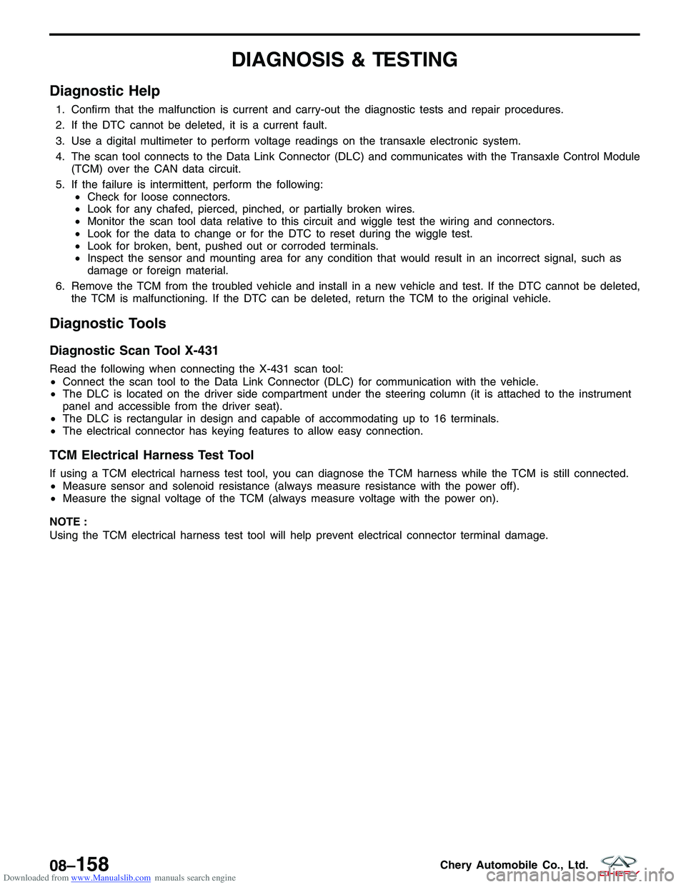
Downloaded from www.Manualslib.com manuals search engine DIAGNOSIS & TESTING
Diagnostic Help
1. Confirm that the malfunction is current and carry-out the diagnostic tests and repair procedures.
2. If the DTC cannot be deleted, it is a current fault.
3. Use a digital multimeter to perform voltage readings on the transaxle electronic system.
4. The scan tool connects to the Data Link Connector (DLC) and communicates with the Transaxle Control Module(TCM) over the CAN data circuit.
5. If the failure is intermittent, perform the following: •Check for loose connectors.
• Look for any chafed, pierced, pinched, or partially broken wires.
• Monitor the scan tool data relative to this circuit and wiggle test the wiring and connectors.
• Look for the data to change or for the DTC to reset during the wiggle test.
• Look for broken, bent, pushed out or corroded terminals.
• Inspect the sensor and mounting area for any condition that would result in an incorrect signal, such as
damage or foreign material.
6. Remove the TCM from the troubled vehicle and install in a new vehicle and test. If the DTC cannot be deleted, the TCM is malfunctioning. If the DTC can be deleted, return the TCM to the original vehicle.
Diagnostic Tools
Diagnostic Scan Tool X-431
Read the following when connecting the X-431 scan tool:
•Connect the scan tool to the Data Link Connector (DLC) for communication with the vehicle.
• The DLC is located on the driver side compartment under the steering column (it is attached to the instrument
panel and accessible from the driver seat).
• The DLC is rectangular in design and capable of accommodating up to 16 terminals.
• The electrical connector has keying features to allow easy connection.
TCM Electrical Harness Test Tool
If using a TCM electrical harness test tool, you can diagnose the TCM harness while the TCM is still connected.
•Measure sensor and solenoid resistance (always measure resistance with the power off).
• Measure the signal voltage of the TCM (always measure voltage with the power on).
NOTE :
Using the TCM electrical harness test tool will help prevent electrical connector terminal damage.
08–158Chery Automobile Co., Ltd.
Page 1307 of 1903

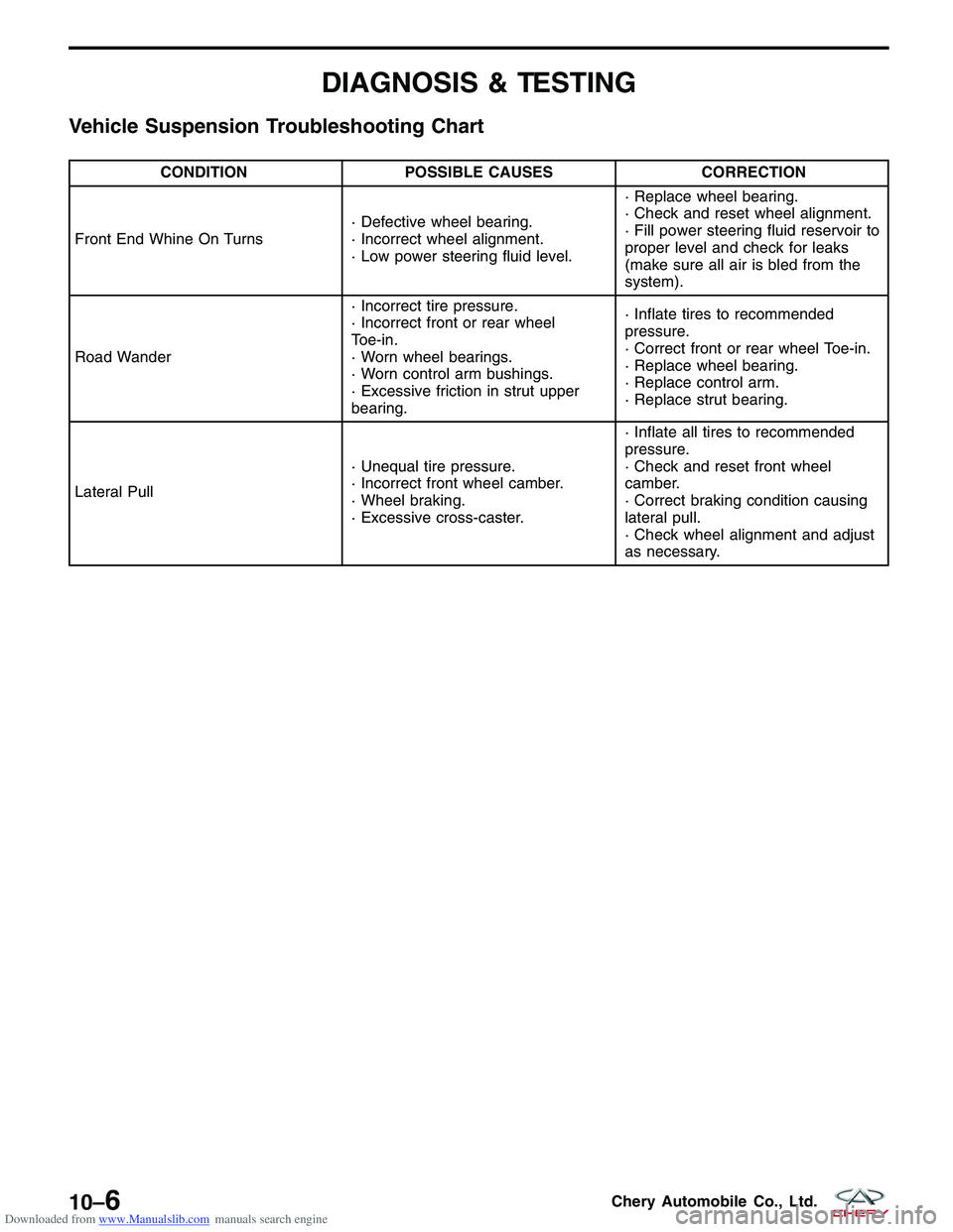
Downloaded from www.Manualslib.com manuals search engine DIAGNOSIS & TESTING
Vehicle Suspension Troubleshooting Chart
CONDITIONPOSSIBLE CAUSES CORRECTION
Front End Whine On Turns · Defective wheel bearing.
· Incorrect wheel alignment.
· Low power steering fluid level.· Replace wheel bearing.
· Check and reset wheel alignment.
· Fill power steering fluid reservoir to
proper level and check for leaks
(make sure all air is bled from the
system).
Road Wander · Incorrect tire pressure.
· Incorrect front or rear wheel
Toe-in.
· Worn wheel bearings.
· Worn control arm bushings.
· Excessive friction in strut upper
bearing.· Inflate tires to recommended
pressure.
· Correct front or rear wheel Toe-in.
· Replace wheel bearing.
· Replace control arm.
· Replace strut bearing.
Lateral Pull · Unequal tire pressure.
· Incorrect front wheel camber.
· Wheel braking.
· Excessive cross-caster.· Inflate all tires to recommended
pressure.
· Check and reset front wheel
camber.
· Correct braking condition causing
lateral pull.
· Check wheel alignment and adjust
as necessary.
10–6Chery Automobile Co., Ltd.
Page 1320 of 1903
Downloaded from www.Manualslib.com manuals search engine 12. Remove the exhaust pipe assembly (See Exhaust Pipe Removal & Installation in Section 07 Exhaust).
13. Remove the high pressure and low pressure lines(1) from the steering gear (drain steering fluid from
lines).
(Tighten: High pressure line to power steering
pump 27 - 33 N·m)
(Tighten: Low pressure line to power steering pump
27 - 33 N·m)
14. Remove the two bolts (1) between the steering gearing and the sub-frame.
(Tighten: Steering gear to sub-frame bolts to 70 -
80 N·m)
ON-VEHICLE SERVICE
LTSM110007
LTSM100024
10
10–19Chery Automobile Co., Ltd.
Page 1356 of 1903
Downloaded from www.Manualslib.com manuals search engine STEERING
11
CONTENTSpage
Steering System ..................................................................... 11-1
Steering Column ..................................................................... 11-8
Steering Gear ...................................................................... 11-18
Power Steering Pump ................................................................ 11-31
STEERING SYSTEM
GENERAL INFORMATION11-2
Description 11-2
Operation 11-2
Specifications 11-3
Special Tools 11-3
DIAGNOSIS & TESTING11-4
Power Steering Troubleshooting Chart 11-4
Power Steering Fluid Troubleshooting
Chart 11-5
ON-VEHICLE SERVICE11-6
Power Steering Filling and Flushing 11-6
Filling 11-6
Flushing 11-6
Inspection 11-7
11
11 –1Chery Automobile Co., Ltd.