2009 CHERY TIGGO suspension
[x] Cancel search: suspensionPage 1343 of 1903
Downloaded from www.Manualslib.com manuals search engine DIAGNOSIS & TESTING
Vehicle Inspection
Inspect the following for damage:
•Inspect the tires.
• Inspect the rims.
Replace any tire or rim that is found to be damaged.
Tire Wear
Inspect the following for accurate tire wear:
• Check the depth of tire remaining tread.
• Standard tire: not less than 1.6 mm.
• Snow tire: 50% tire tread.
If the tread is below the specifications, the tire should be replaced.
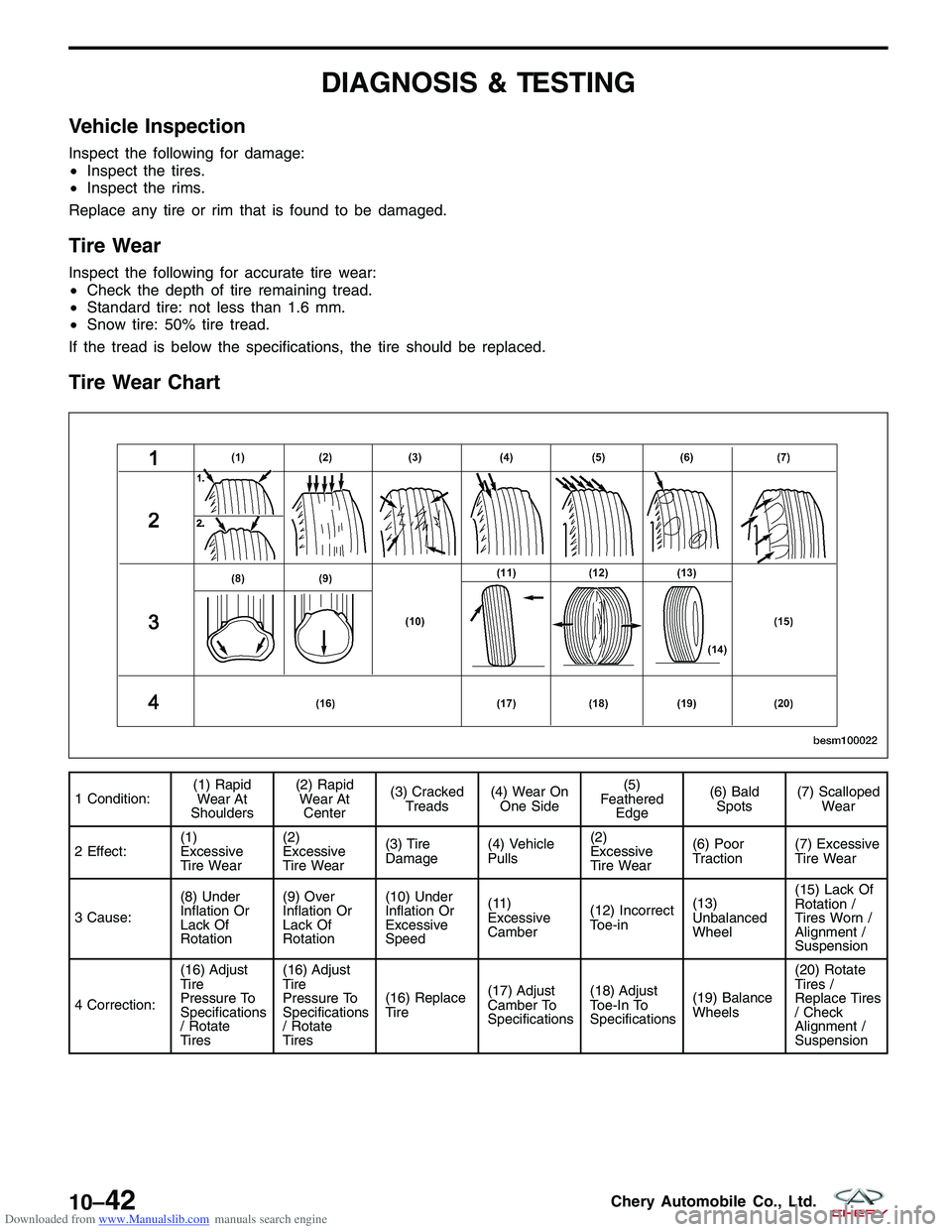
Tire Wear Chart
1 Condition: (1) Rapid
Wear At
Shoulders (2) Rapid
Wear At Center (3) Cracked
Treads (4) Wear On
One Side (5)
Feathered Edge (6) Bald
Spots (7) Scalloped
Wear
2 Effect: (1)
Excessive
Tire Wear(2)
Excessive
Tire Wear
(3) Tire
Damage
(4) Vehicle
Pulls(2)
Excessive
Tire Wear(6) Poor
Traction
(7) Excessive
Tire Wear
3 Cause: (8) Under
Inflation Or
Lack Of
Rotation(9) Over
Inflation Or
Lack Of
Rotation(10) Under
Inflation Or
Excessive
Speed
(11)
Excessive
Camber
(12) Incorrect
Toe-in(13)
Unbalanced
Wheel(15) Lack Of
Rotation /
Tires Worn /
Alignment /
Suspension
4 Correction: (16) Adjust
Tire
Pressure To
Specifications
/ Rotate
Tires(16) Adjust
Tire
Pressure To
Specifications
/ Rotate
Tires
(16) Replace
Tire
(17) Adjust
Camber To
Specifications(18) Adjust
Toe-In To
Specifications
(19) Balance
Wheels(20) Rotate
Tires /
Replace Tires
/ Check
Alignment /
Suspension
BESM100022
10–42Chery Automobile Co., Ltd.
Page 1344 of 1903
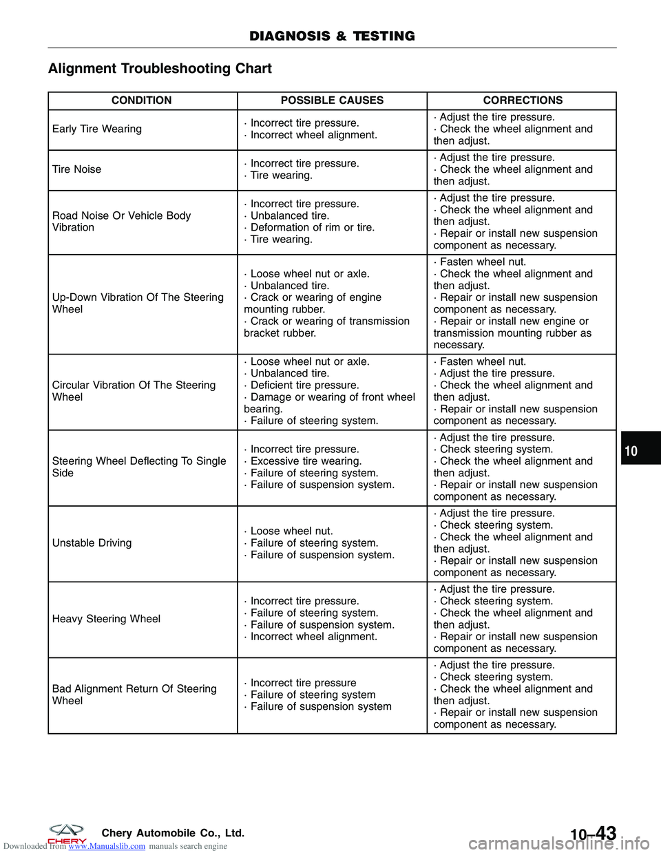
Downloaded from www.Manualslib.com manuals search engine Alignment Troubleshooting Chart
CONDITIONPOSSIBLE CAUSES CORRECTIONS
Early Tire Wearing · Incorrect tire pressure.
· Incorrect wheel alignment.· Adjust the tire pressure.
· Check the wheel alignment and
then adjust.
Tire Noise · Incorrect tire pressure.
· Tire wearing.· Adjust the tire pressure.
· Check the wheel alignment and
then adjust.
Road Noise Or Vehicle Body
Vibration · Incorrect tire pressure.
· Unbalanced tire.
· Deformation of rim or tire.
· Tire wearing.· Adjust the tire pressure.
· Check the wheel alignment and
then adjust.
· Repair or install new suspension
component as necessary.
Up-Down Vibration Of The Steering
Wheel · Loose wheel nut or axle.
· Unbalanced tire.
· Crack or wearing of engine
mounting rubber.
· Crack or wearing of transmission
bracket rubber.· Fasten wheel nut.
· Check the wheel alignment and
then adjust.
· Repair or install new suspension
component as necessary.
· Repair or install new engine or
transmission mounting rubber as
necessary.
Circular Vibration Of The Steering
Wheel · Loose wheel nut or axle.
· Unbalanced tire.
· Deficient tire pressure.
· Damage or wearing of front wheel
bearing.
· Failure of steering system.· Fasten wheel nut.
· Adjust the tire pressure.
· Check the wheel alignment and
then adjust.
· Repair or install new suspension
component as necessary.
Steering Wheel Deflecting To Single
Side · Incorrect tire pressure.
· Excessive tire wearing.
· Failure of steering system.
· Failure of suspension system.· Adjust the tire pressure.
· Check steering system.
· Check the wheel alignment and
then adjust.
· Repair or install new suspension
component as necessary.
Unstable Driving · Loose wheel nut.
· Failure of steering system.
· Failure of suspension system.· Adjust the tire pressure.
· Check steering system.
· Check the wheel alignment and
then adjust.
· Repair or install new suspension
component as necessary.
Heavy Steering Wheel · Incorrect tire pressure.
· Failure of steering system.
· Failure of suspension system.
· Incorrect wheel alignment.· Adjust the tire pressure.
· Check steering system.
· Check the wheel alignment and
then adjust.
· Repair or install new suspension
component as necessary.
Bad Alignment Return Of Steering
Wheel · Incorrect tire pressure
· Failure of steering system
· Failure of suspension system· Adjust the tire pressure.
· Check steering system.
· Check the wheel alignment and
then adjust.
· Repair or install new suspension
component as necessary.
DIAGNOSIS & TESTING
10
10–43Chery Automobile Co., Ltd.
Page 1352 of 1903
Downloaded from www.Manualslib.com manuals search engine ON-VEHICLE SERVICE
Tire Repair
Description
Tires are designed and engineered for each specific vehicle. They provide the best overall performance for normal
operation. The ride and handling characteristics match the vehicle’s requirements. With proper care they will give
excellent reliability, traction, skid resistance, and tread life.
WARNING!
Failure to equip the vehicle with tires having adequate speed capability can result in sudden tire failure.
In order to maintain the speed capability of the vehicle, replacement tires must have speed ratings equal to or
higher than those fitted to the vehicle as original equipment. If tires with lower speed ratings are fitted, the vehi-
cle’s handling may be affected and the speed capability of the vehicle may be lowered to the maximum speed
capability of the replacement tires. To avoid an accident resulting in severe or fatal injury, consult the tire man-
ufacturer in regards to maximum speed ratings.
Replacement Procedure
Note the following guidelines when replacing a tire:
•It is recommended that tires equivalent to the original equipment tires be used when replacement is needed.
• Failure to use equivalent replacement tires may adversely affect the safety and handling of the vehicle.
• The use of tires smaller than the minimum tire size approved for the vehicle can result in tire overloading and
failure.
• Use tires that have the approved load rating for the vehicle and never overload them.
• Failure to equip the vehicle with tires having adequate speed capability can result in sudden tire failure and
loss of vehicle control.
• The use of oversize tires may cause interference with vehicle components. Under extremes of suspension and
steering travel, interference with vehicle components may cause tire damage.
Perform the following when replacing a tire: 1. Raise and support the vehicle.
2. Remove the wheel mounting nuts and the wheel assembly.
3. Deflate the tire completely before removing the tire from the wheel.
4. Use lubrication such as a mild soap solution when dismounting or mounting tire.
5. Replace the tire with a tire approved for the vehicle.
6. Use tools free of burrs or sharp edges which could damage the tire or wheel rim.
7. Before mounting tire on wheel, make sure all rust is removed from the rim bead and repaint if necessary.
8. Balance the wheel assembly.
9. Install the wheel assembly and install the wheel mounting nuts. (Tighten: Wheel mounting nuts to 110 N·m)
Repair Procedure
Note the following guidelines when performing a tire repair:
•For proper repairing, a radial tire must be removed from the wheel.
• Repairs should only be made if the defect, or puncture, is in the tread area.
• The tire should be replaced if the puncture is located in the sidewall.
Perform the following when repairing a tire: 1. Raise and support the vehicle.
2. Remove the wheel mounting nuts and the wheel assembly.
3. Deflate the tire completely before removing the tire from the wheel.
4. Use lubrication such as a mild soap solution when dismounting or mounting tire.
5. Repair the tire only if the defect, or puncture, is in the tread area.
6. Use tools free of burrs or sharp edges which could damage the tire or wheel rim.
7. Before mounting tire on wheel, make sure all rust is removed from the rim bead and repaint if necessary.
10–51Chery Automobile Co., Ltd.
Page 1366 of 1903
Downloaded from www.Manualslib.com manuals search engine DIAGNOSIS & TESTING
Vehicle Inspection
There is some noise in all power steering systems. One of the most common is a hissing sound. Hiss is a high
frequency noise similar to that of a water tap being closed slowly. The noise is present in all valves that have a high
velocity steering fluid passing through an orifice. There is no relationship between this noise and steering perfor-
mance. The hissing sound is commonly heard during the following operations:
•Evident at a standstill
• At park with the engine running
• When the steering wheel is at the end of its travel
Loose Steering / Vehicle Leads / Drifts Troubleshooting Chart
CONDITION POSSIBLE CAUSES CORRECTION
Excessive Play In Steering Wheel · Worn or loose suspension or
steering components.
· Worn or loose wheel bearings.
· Steering gear mounting.
· Gear out of adjustment.
· Worn or loose steering coupler.· Repair if necessary.
· Repair if necessary.
· Tighten gear mounting bolts to
specification.
· Adjust gear to specification.
· Repair if necessary.
Vehicle Pulls To One Side During
Braking · Tire pressure.
· Air in brake hydraulics system.
· Worn brake components.· Adjust tire pressure.
· Bleed brake system.
· Repair if necessary.
Vehicle Leads Or Drifts From
Straight Ahead Direction On
Uncrowned Road · Tire pressure.
· Radial tire lead.
· Brakes dragging.
· Wheel alignment.
· Weak or broken strut.
· Loose or worn steering/suspension
components.· Adjust tire pressure.
· Cross front tires.
· Repair if necessary.
· Align vehicle.
· Replace strut.
· Repair if necessary.
11
11 –11Chery Automobile Co., Ltd.
Page 1374 of 1903
Downloaded from www.Manualslib.com manuals search engine GENERAL INFORMATION
Description
The steering gear used is the rack-and-pinion type with power assist. It is mounted on the front suspension sub-
frame. The outer ends of the outer tie rods attach to the front knuckles.
NOTE :
The power steering gear should not be serviced or adjusted. If a malfunction or steering fluid leak occurs with the
steering gear, the complete steering gear needs to be replaced.
Operation
The steering wheel turns the pinion. The rack is a long flat bar with geared teeth on one side. The rack teeth mesh
with the teeth on the pinion gear. Rotation of the pinion moves the rack from left to right and right to left. The tie rod
then causes the wheels to turn to the left or right.
Specifications
Torque Specifications
DESCRIPTIONTORQUE (N·m)
Inlet / Outlet Pipe Nut 25 - 30
Intermediate Shaft Bolt 25 - 30
Steering Gear to Sub-Frame Bolts 70 - 80
Sub-Frame Assembly Bolts 180 ± 15
Tie Rod End Nut 32 - 38
Tie Rod Jam Nut 15
Wheel Mounting Nuts 110
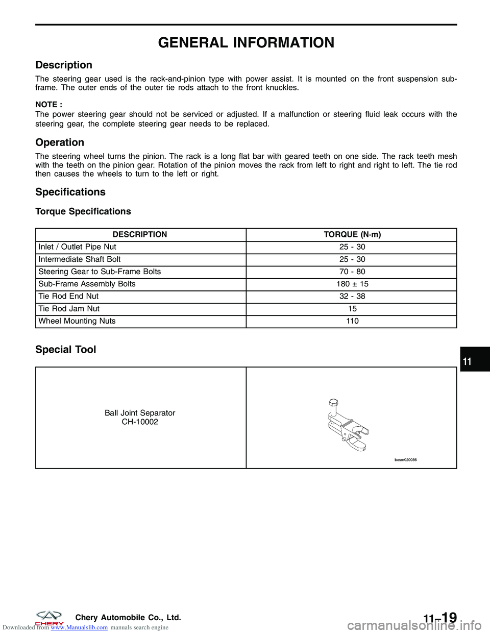
Special Tool
Ball Joint Separator
CH-10002
11
11 –19Chery Automobile Co., Ltd.
Page 1375 of 1903
Downloaded from www.Manualslib.com manuals search engine DIAGNOSIS & TESTING
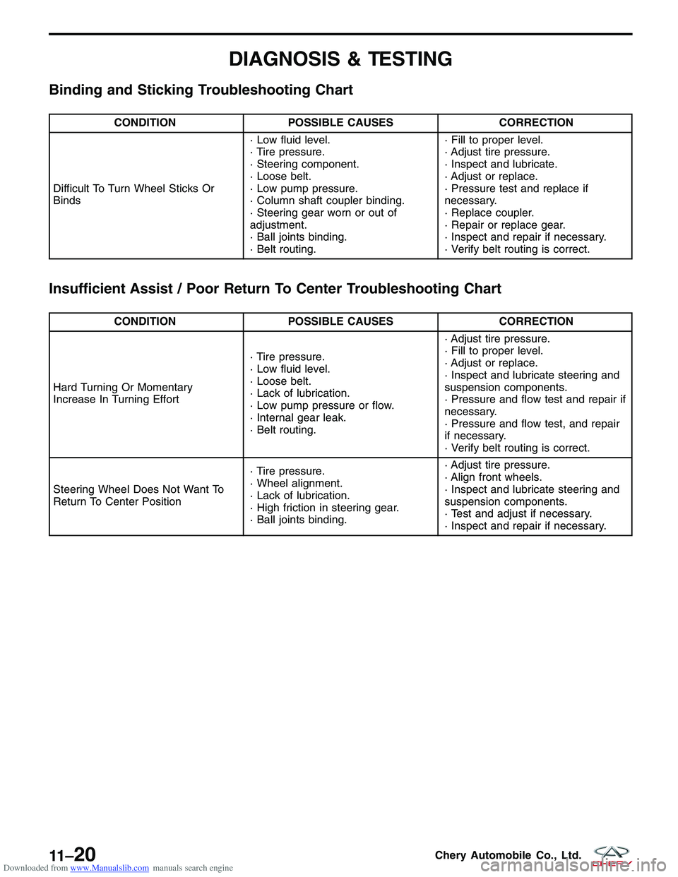
Binding and Sticking Troubleshooting Chart
CONDITIONPOSSIBLE CAUSES CORRECTION
Difficult To Turn Wheel Sticks Or
Binds · Low fluid level.
· Tire pressure.
· Steering component.
· Loose belt.
· Low pump pressure.
· Column shaft coupler binding.
· Steering gear worn or out of
adjustment.
· Ball joints binding.
· Belt routing.· Fill to proper level.
· Adjust tire pressure.
· Inspect and lubricate.
· Adjust or replace.
· Pressure test and replace if
necessary.
· Replace coupler.
· Repair or replace gear.
· Inspect and repair if necessary.
· Verify belt routing is correct.
Insufficient Assist / Poor Return To Center Troubleshooting Chart
CONDITION
POSSIBLE CAUSES CORRECTION
Hard Turning Or Momentary
Increase In Turning Effort · Tire pressure.
· Low fluid level.
· Loose belt.
· Lack of lubrication.
· Low pump pressure or flow.
· Internal gear leak.
· Belt routing.· Adjust tire pressure.
· Fill to proper level.
· Adjust or replace.
· Inspect and lubricate steering and
suspension components.
· Pressure and flow test and repair if
necessary.
· Pressure and flow test, and repair
if necessary.
· Verify belt routing is correct.
Steering Wheel Does Not Want To
Return To Center Position · Tire pressure.
· Wheel alignment.
· Lack of lubrication.
· High friction in steering gear.
· Ball joints binding.· Adjust tire pressure.
· Align front wheels.
· Inspect and lubricate steering and
suspension components.
· Test and adjust if necessary.
· Inspect and repair if necessary.
11 –20Chery Automobile Co., Ltd.
Page 1379 of 1903
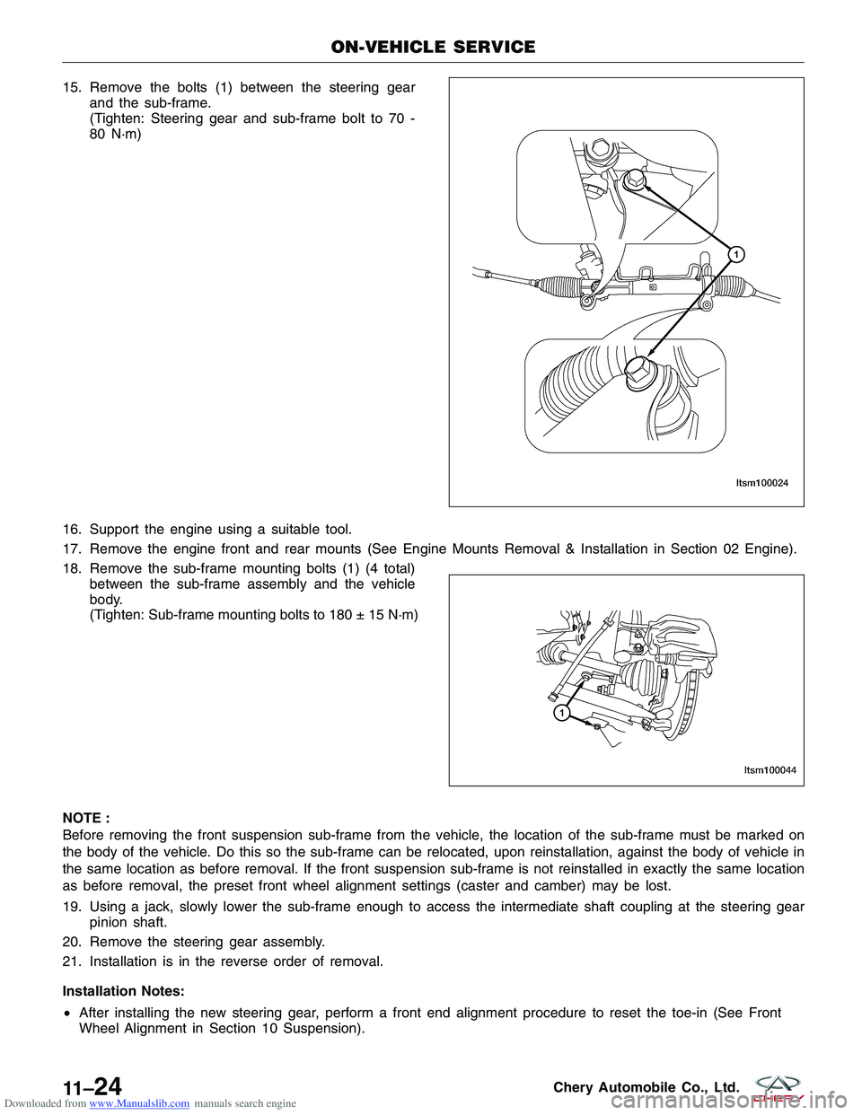
Downloaded from www.Manualslib.com manuals search engine 15. Remove the bolts (1) between the steering gearand the sub-frame.
(Tighten: Steering gear and sub-frame bolt to 70 -
80 N·m)
16. Support the engine using a suitable tool.
17. Remove the engine front and rear mounts (See Engine Mounts Removal & Installation in Section 02 Engine).
18. Remove the sub-frame mounting bolts (1) (4 total) between the sub-frame assembly and the vehicle
body.
(Tighten: Sub-frame mounting bolts to 180 ± 15 N·m)
180 ± 15 N·m)
NOTE :
Before removing the front suspension sub-frame from the vehicle, the location of the sub-frame must be marked on
the body of the vehicle. Do this so the sub-frame can be relocated, upon reinstallation, against the body of vehicle in
the same location as before removal. If the front suspension sub-frame is not reinstalled in exactly the same location
as before removal, the preset front wheel alignment settings (caster and camber) may be lost.
19. Using a jack, slowly lower the sub-frame enough to access the intermediate shaft coupling at the steering gear pinion shaft.
20. Remove the steering gear assembly.
21. Installation is in the reverse order of removal.
Installation Notes:
• After installing the new steering gear, perform a front end alignment procedure to reset the toe-in (See Front
Wheel Alignment in Section 10 Suspension).
ON-VEHICLE SERVICE
LTSM100024
LTSM100044
11 –24Chery Automobile Co., Ltd.
Page 1383 of 1903
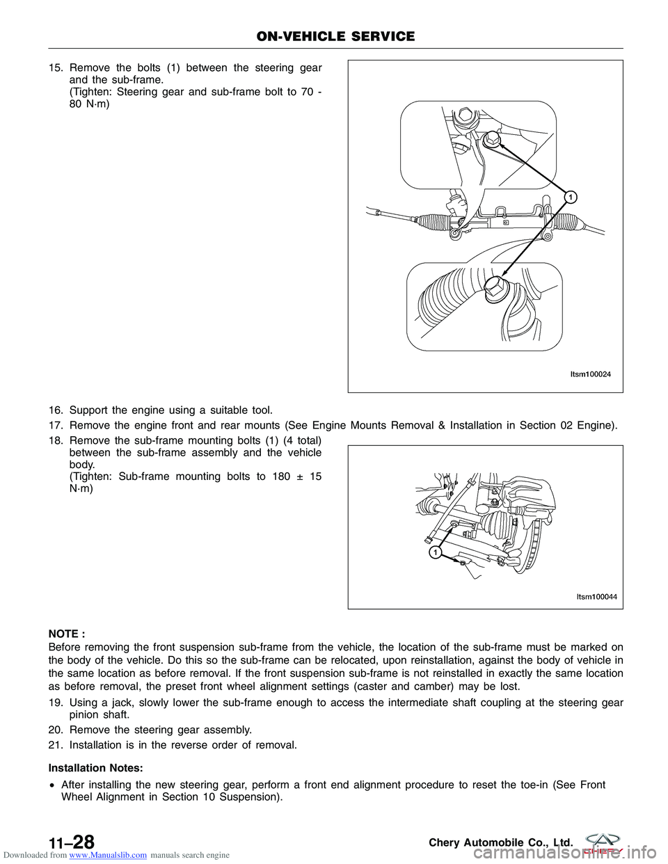
Downloaded from www.Manualslib.com manuals search engine 15. Remove the bolts (1) between the steering gearand the sub-frame.
(Tighten: Steering gear and sub-frame bolt to 70 -
80 N·m)
16. Support the engine using a suitable tool.
17. Remove the engine front and rear mounts (See Engine Mounts Removal & Installation in Section 02 Engine).
18. Remove the sub-frame mounting bolts (1) (4 total) between the sub-frame assembly and the vehicle
body.
(Tighten: Sub-frame mounting bolts to 180 ± 15
N·m)
NOTE :
Before removing the front suspension sub-frame from the vehicle, the location of the sub-frame must be marked on
the body of the vehicle. Do this so the sub-frame can be relocated, upon reinstallation, against the body of vehicle in
the same location as before removal. If the front suspension sub-frame is not reinstalled in exactly the same location
as before removal, the preset front wheel alignment settings (caster and camber) may be lost.
19. Using a jack, slowly lower the sub-frame enough to access the intermediate shaft coupling at the steering gear pinion shaft.
20. Remove the steering gear assembly.
21. Installation is in the reverse order of removal.
Installation Notes:
• After installing the new steering gear, perform a front end alignment procedure to reset the toe-in (See Front
Wheel Alignment in Section 10 Suspension).
ON-VEHICLE SERVICE
LTSM100024
LTSM100044
11 –28Chery Automobile Co., Ltd.