Page 544 of 1903

Downloaded from www.Manualslib.com manuals search engine 10.CHECK STARTER RELAY CONTROL CIRCUIT
• Disconnect ECM harness connector.
• Disconnect front fuse and relay box harness connector A.
• Check harness continuity between ECM terminal 14 and front fuse and relay box terminal A1.
• Check harness continuity between front fuse and relay box terminal G2 and G5.
• Continuity should exist.
• Also check harness for short to ground and short to power.
Is the check result normal?
Ye s>>Go to the next step.
No
>>Repair circuit for an open or short to ground or short to power in harness or connectors.
11 .CHECK FUSE
• Disconnect fuse 23 (10A), fuse 24 (5A) in front fuse and relay box.
• Check fuses.
Is the check result normal?
Ye s>>Go to the next step.
No
>>Replace fuse 23 or 24.
12.CHECK FRONT FUSE AND RELAY BOX
• Check the front fuse and relay box for damage.
Is the check result normal?
Ye s>>Go to the next step.
No
>>Replace front fuse and relay box.
13.REPLACE AND PROGRAM ECM
• Replace the ECM.
NOTE :
The Immobilizer control module must be matched to the new ECM (See ECM Removal & Installation in Section 03
Electronic Engine Controls).
DIAGNOSIS & TESTING
03–260Chery Automobile Co., Ltd.
Page 549 of 1903

Downloaded from www.Manualslib.com manuals search engine 4.DETECT MALFUNCTIONING PART
• Check the following:
� Harness connectors A-102, E-105
� Front fuse and relay box F3
� Fuse 22, Fuse 12
� Check harness for open or short between CMP sensor and fuse.
• With the X-431 scan tool, read ECM DTCs.
Is DTC P0016 still present?
Ye s>>Go to the next step.
No
>>The system is now operating properly.
Reassemble the vehicle and road test to verify the customers complaint is repaired.
5.CHECK CMP SENSOR GROUND CIRCUIT FOR AN OPEN AND SHORT
• Turn ignition switch off.
• Check harness continuity between CMP sensor terminal 1 and ground.
• Continuity should exist.
Is the check result normal?
Ye s>>Go to the next step.
No
>>Repair or replace circuit for an open or short to power in harness or connectors.
6.CHECK CMP SENSOR INPUT SIGNAL CIRCUIT FOR AN OPEN AND SHORT
• Turn ignition switch on.
• Check voltage between CMP sensor terminal 2 and ground.
• 11 V should exist.
Is the check result normal?
Ye s>>Go to the next step.
No
>>Repair or replace circuit for an open or short to power or short to ground in harness or connectors.
If circuit is normal, go to the next step.
DIAGNOSIS & TESTING
03
03–265Chery Automobile Co., Ltd.
Page 559 of 1903

Downloaded from www.Manualslib.com manuals search engine 4.DETECT MALFUNCTIONING PART
• Check the following:
� Harness connectors A-102, E-105
� Front fuse and relay box H2, H5
� Fuse 25, fuse 12, fuse 23, fuse 24
• Check harness for an open or short between O
2sensor and fuse.
• Repair or replace malfunctioning part.
• With the X-431, select view DTC.
Is DTC P0031 still present?
Ye s>>Go to the next step.
No
>>The system is normal now.
5.CHECK O2SENSOR HEATER CONTROL CIRCUIT FOR OPEN OR SHORT
• Turn ignition switch off.
• Disconnect ECM connector.
• Check harness continuity between ECM terminal and O
2sensor terminal.
COMPONENT ECMUPSTREAM O2SENSOR
TERMINAL •
48 (With EOBD)
• 1 (Without EOBD) 1
• Continuity should exist.
• Check harness for short to ground.
Is the check result normal?
Ye s>>Go to the next step.
No
>>Repair the circuit for an open or short in harness or connectors.
6.CHECK O2SENSOR HEATER
• Check resistance between O
2sensor heater terminals.
TERMINAL NO. RESISTANCE
1 and 2 (including cable
and connector) Approximately 9
�
DIAGNOSIS & TESTING
03
03–275Chery Automobile Co., Ltd.
Page 564 of 1903

Downloaded from www.Manualslib.com manuals search engine 4.DETECT MALFUNCTIONING PART
• Check the following:
� Harness connectors A-102, E-105
� Front fuse and relay box H2, H5
� Fuse 25, Fuse 12, Fuse 23, Fuse 24
• Check harness for open or short between O
2sensor and fuse.
• Repair or replace malfunctioning part.
• With the X-431, select view DTC.
Is DTC P0032 still present?
Ye s>>Go to the next step.
No
>>The system is now operating properly.
Reassemble the vehicle and road test to verify the customers complaint is repaired.
5.CHECK O2SENSOR HEATER CONTROL CIRCUIT FOR A SHORT
• Turn ignition switch off.
• Disconnect ECM connector.
• Check harness continuity between ECM terminal and O
2sensor terminal.
COMPONENT ECMUPSTREAM O2SENSOR
TERMINAL •
48 (With EOBD)
• 1 (Without EOBD) 1
• Continuity should exist.
• Check harness short to power supply circuit.
Is the check result normal?
Ye s>>Go to the next step.
No
>>Repair circuit for a short to power in harness or connectors.
6.CHECK THE O2SENSOR HEATER
• Check resistance between O
2sensor heater terminals.
TERMINAL NO. RESISTANCE
1 & 2 (including
cable and connector) Approximately 9
�
DIAGNOSIS & TESTING
03–280Chery Automobile Co., Ltd.
Page 569 of 1903

Downloaded from www.Manualslib.com manuals search engine 5.DETECT MALFUNCTIONING PART
• Check the following parts:
� Relay
� Fuse 23, fuse 24, fuse 12
� Harness connectors A-102, E-105
• Check harness for an open or short between MAF sensor and fuse.
• Repair an open circuit or short to ground in harness or connectors.
• With the X-431, view DTC in ECM.
Is DTC P0102 present?
Ye s>>Go to the next step.
No
>>The system is now operating properly.
Reassemble the vehicle and road test to verify the customers complaint is repaired.
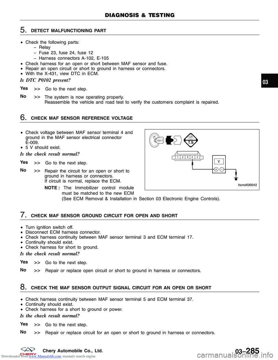
6.CHECK MAF SENSOR REFERENCE VOLTAGE
• Check voltage between MAF sensor terminal 4 and
ground in the MAF sensor electrical connector
E-009.
• 5 V should exist.
Is the check result normal?
Ye s>>Go to the next step.
No
>>Repair the circuit for an open or short to
ground in harness or connectors.
If circuit is normal, replace the ECM.
NOTE : The Immobilizer control module
must be matched to the new ECM
(See ECM Removal & Installation in Section 03 Electronic Engine Controls).
7.CHECK MAF SENSOR GROUND CIRCUIT FOR OPEN AND SHORT
• Turn ignition switch off.
• Disconnect ECM harness connector.
• Check harness continuity between MAF sensor terminal 3 and ECM terminal 17.
• Continuity should exist.
• Check harness for short to ground.
Is the check result normal?
Ye s>>Go to the next step.
No
>>Repair or replace open circuit or short to ground in harness or connectors.
8.CHECK THE MAF SENSOR OUTPUT SIGNAL CIRCUIT FOR AN OPEN OR SHORT
• Check harness continuity between MAF sensor terminal 5 and ECM terminal 37.
• Continuity should exist.
• Check harness for a short to ground or power.
Is the check result normal?
Ye s>>Go to the next step.
No
>>Repair or replace circuit for an open or short to ground in harness or connectors.
DIAGNOSIS & TESTING
LTSMD030042
03
03–285Chery Automobile Co., Ltd.
Page 633 of 1903
Downloaded from www.Manualslib.com manuals search engine 6.CHECK INJECTOR POWER SUPPLY CIRCUIT FOR OPEN
• Turn ignition switch on.
• Check injector supply voltage between sensor ter-
minal and ground in the electrical connector.
• Battery voltage should exist.
Is the check result normal?
Ye s>>Go to step 8.
No
>>Go to the next step.
7.DETECT MALFUNCTIONING PART
• Check the following:
� Harness connectors A-102, E-105
� Front fuse and relay box F3
� Fuse 12, fuse 23, fuse 24
� Check harness for an open or short to ground between injector and fuse.
Is the check result normal?
Ye s>>With the X-431, check the system, If OK, go to the next step.
No
>>Repair or replace malfunctioning part.
8.CHECK INJECTOR CONTROL CIRCUITS FOR AN OPEN
• Check injector control circuit voltage.
• 3.6 V should exist.
Is the check result normal?
Ye s>>Go to step 10.
No
>>Go to the next step.
DIAGNOSIS & TESTING
LTSMD030024
03
03–349Chery Automobile Co., Ltd.
Page 647 of 1903
Downloaded from www.Manualslib.com manuals search engine 6.CHECK INJECTOR POWER SUPPLY CIRCUIT FOR AN OPEN
• Turn ignition switch on.
• Check injector supply voltage between sensor ter-
minal and ground in the electrical connector.
• Battery voltage should exist.
Is the check result normal?
Ye s>>Go to step 8.
No
>>Go to the next step.
7.DETECT MALFUNCTIONING PART
• Check the following:
� Harness connectors A-102, E-105
� Front fuse and relay box F3
� Fuse 12, fuse 23, fuse 24
� Harness for shorted between injector and fuse
Is the check result normal?
Ye s>>Go to the next step.
No
>>Repair malfunctioning part.
8.CHECK INJECTOR CONTROL CIRCUITS FOR A SHORT
• Check injector control circuit voltage.
• 3.6 V should exist.
Is the check result normal?
Ye s>>Go to step 10.
No
>>Go to the next step.
DIAGNOSIS & TESTING
LTSMD030024
03
03–363Chery Automobile Co., Ltd.
Page 654 of 1903

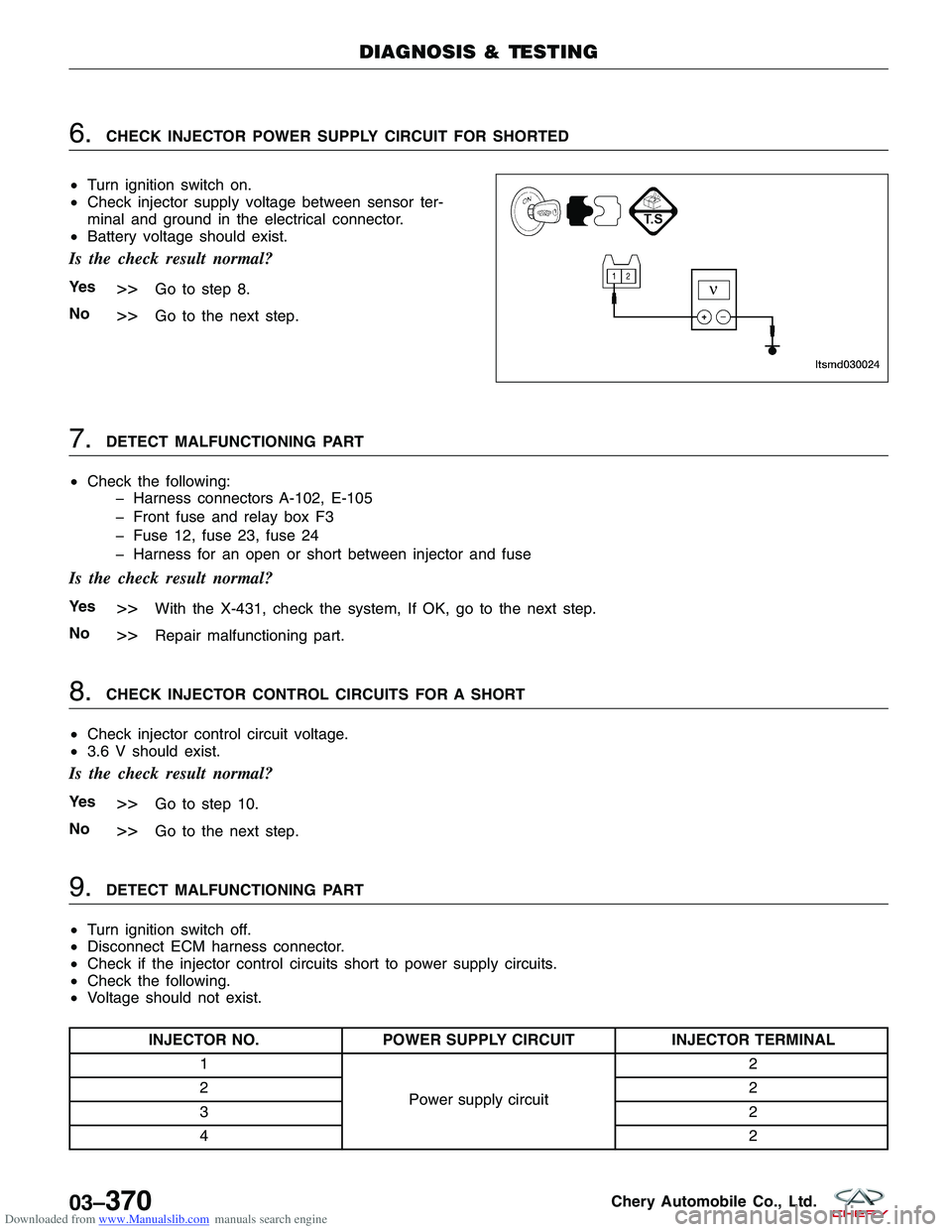
Downloaded from www.Manualslib.com manuals search engine 6.CHECK INJECTOR POWER SUPPLY CIRCUIT FOR SHORTED
• Turn ignition switch on.
• Check injector supply voltage between sensor ter-
minal and ground in the electrical connector.
• Battery voltage should exist.
Is the check result normal?
Ye s>>Go to step 8.
No
>>Go to the next step.
7.DETECT MALFUNCTIONING PART
• Check the following:
� Harness connectors A-102, E-105
� Front fuse and relay box F3
� Fuse 12, fuse 23, fuse 24
� Harness for an open or short between injector and fuse
Is the check result normal?
Ye s>>With the X-431, check the system, If OK, go to the next step.
No
>>Repair malfunctioning part.
8.CHECK INJECTOR CONTROL CIRCUITS FOR A SHORT
• Check injector control circuit voltage.
• 3.6 V should exist.
Is the check result normal?
Ye s>>Go to step 10.
No
>>Go to the next step.
9.DETECT MALFUNCTIONING PART
• Turn ignition switch off.
• Disconnect ECM harness connector.
• Check if the injector control circuits short to power supply circuits.
• Check the following.
• Voltage should not exist.
INJECTOR NO. POWER SUPPLY CIRCUIT INJECTOR TERMINAL
1
Power supply circuit 2
2 2
3 2
4 2
DIAGNOSIS & TESTING
LTSMD030024
03–370Chery Automobile Co., Ltd.