Page 934 of 1903

Downloaded from www.Manualslib.com manuals search engine Operation
The radiator cooling fan operation is controlled by the Engine Control Module (ECM) and the fan relays, with inputs
from the following:
•Engine coolant temperature
• Automatic transaxle fluid temperature (with DP0 transaxle)
• A/C signal
Inspect the cooling fan for proper low speed and high speed operation:
• The low speed fan should be switched on at 98°C and switched off at 94°C.
• The high speed fan should be switched on at 105°C and switched off at 101°C.
• If the water temperature is greater than 101°C after the fan is switched off, the fan will continue to operate for
1 minute.
• If the water temperature is greater than 94°C after the fan is switched off, the fan will continue to operate for
0.5 minute.
• If the water temperature is less than 85°C after the fan is switched off, the fan will stop operating.
Removal & Installation
WARNING!
Always allow the engine to cool before opening the cooling system. Do not remove the coolant pressure relief
cap when the engine is operating or the cooling system is hot. The cooling system is under pressure; steam and
hot liquid can come out forcefully when the cap is loosened slightly. Failure to follow these instructions may
result in serious personal injury.
1. Disconnect the negative battery cable.
2. Drain the cooling system (See Cooling System Draining Procedure in Section 06 Cooling System).
3. Disconnect the upper radiator hose from the radiator.
4. Disconnect the cooling fan electrical connector and the cooling fan ground cable connected to the body.
5. Remove the cooling fan mounting bolts (1) to the
radiator.
(Tighten: Cooling fan mounting bolts to 5 N·m)
6. Remove the radiator fan from the engine compartment.
7. Remove the cooling fan from its support, if necessary.
8. Installation is in the reverse order of removal.
Installation Notes:
• Verify the cooling system is filled to proper specifications.
Cooling Fan Inspection
1. Using the following table, apply battery voltage to the specified connector terminals.
2. Verify that the fan motor operates smoothly when voltage is applied.
3. If the test results are not as specified, replace the fan motor.
ON-VEHICLE SERVICE
LTSM060008
06
06–19Chery Automobile Co., Ltd.
Page 950 of 1903
Downloaded from www.Manualslib.com manuals search engine Specifications
Torque Specifications
DESCRIPTIONTORQUE (N·m)
Drain Plug 33
Engine To Transaxle Bolts 80
Side Sill To Vehicle Body Bolts 120
Front Mount Bolts 60
Rear Mount Bolts 40
Fluid Pan Bolts 50
Transaxle Mount Nuts 120
Transaxle Mount Bolts 40
Drive Plate Bolts (automatic transaxle) 75
Gear Ratio Specifications
GEAR SELECTOR POSITIONRATIO
First 2.75
Second 1.5
Third 1
Overdrive 0.71
Reverse 2.45
Lubrication Specifications
DESCRIPTIONITEM
Transaxle Fluid Quantity 6.0L
Transaxle Fluid Change Quantity 3.0L
Fluid Type DEXTRON III
Fluid Change Cycle 40000 Km
GENERAL INFORMATION
08
08–7Chery Automobile Co., Ltd.
Page 1183 of 1903

Downloaded from www.Manualslib.com manuals search engine ON-VEHICLE SERVICE
F4A4 Automatic Transaxle Assembly
Removal & Installation
1. Raise and support the vehicle.
2. Disconnect the negative battery cable.
3. Remove the battery and battery tray (See Battery Removal & Installation in Section 05 Starting & Charging).
4. Remove the air cleaner and air duct assembly.
5. Drain the cooling system (See Cooling System Draining Procedure in Section 06 Cooling System).
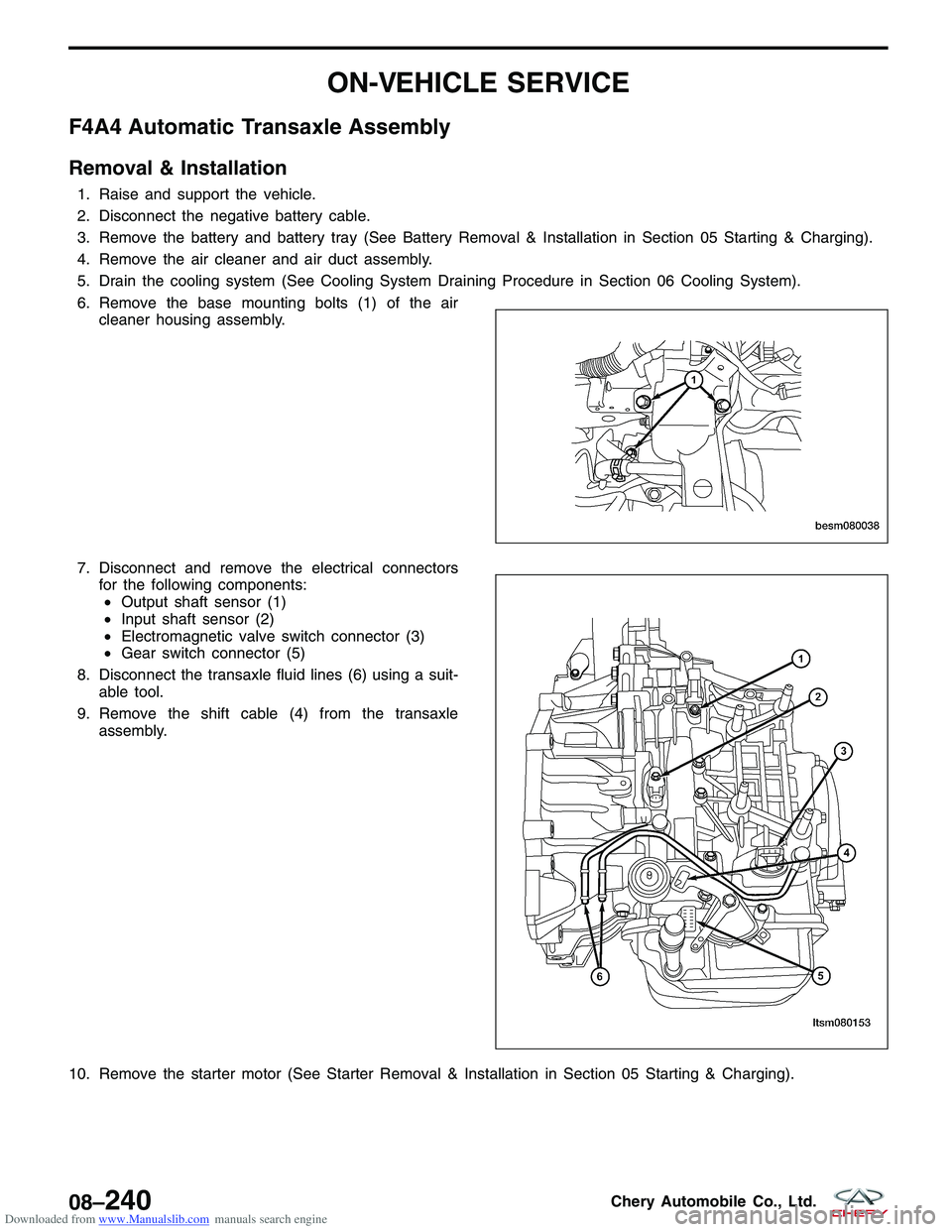
6. Remove the base mounting bolts (1) of the aircleaner housing assembly.
7. Disconnect and remove the electrical connectors for the following components:• Output shaft sensor (1)
• Input shaft sensor (2)
• Electromagnetic valve switch connector (3)
• Gear switch connector (5)
8. Disconnect the transaxle fluid lines (6) using a suit- able tool.
9. Remove the shift cable (4) from the transaxle assembly.
10. Remove the starter motor (See Starter Removal & Installation in Section 05 Starting & Charging).
BESM080038
LTSM080153
08–240Chery Automobile Co., Ltd.
Page 1184 of 1903
Downloaded from www.Manualslib.com manuals search engine 11. Remove the bolts (1) attaching the drive plate tothe torque converter.
(Tighten: Drive plate bolts to 75 N·m)
12. Support the engine using an engine support fixture or suitable jack.
13. Remove the engine to transaxle upper bolts and remove the bracket. (Tighten: Engine to transaxle upper bolts to 80 N·m)
14. Remove transaxle mount nuts (2) and the transaxle mount bracket bolts (1).
(Tighten: Transaxle mount nuts to 120 N·m)
15. Raise the vehicle.
16. Remove the drain plug (1) and drain the transaxle fluid.
ON-VEHICLE SERVICE
BESM080058
LTSM020156
LTSM080190
08
08–241Chery Automobile Co., Ltd.
Page 1205 of 1903
Downloaded from www.Manualslib.com manuals search engine 14. Remove transaxle mount nuts (2) and the transaxlemount bracket bolts (1).
(Tighten: Transaxle mount nuts to 120 N·m)
15. Raise the vehicle.
16. Remove the transaxle drain plug (1) and drain the transaxle fluid.
17. Remove both front axle shafts (See Front Axle Shaft Removal & Installation in Section 09 Driveline & Axle).
18. Remove the engine undercover and splash shields.
19. Remove the front engine mount bolts (1). (Tighten: Front mount bolts to 60 N·m)
ON-VEHICLE SERVICE
LTSM020156
VISM030007
BESM080035
08–262Chery Automobile Co., Ltd.
Page 1271 of 1903
Downloaded from www.Manualslib.com manuals search engine ON-VEHICLE SERVICE
Transfer Case
Removal & Installation
1. Drain the gear fluid from the transfer case.•Fluid-filling plug (1)
• Fluid-limiting plug (2)
• Fluid-drain plug (3)
2. Remove the front intermediate drive shaft assembly.
3. Remove the sub-frame assembly.
4. Remove the left and right front axle shaft mounting bolts (1).
5. Remove the transaxle and transfer case assembly (See Transaxle Assembly Removal & Installation in Section 08 Transaxle).
6. Remove the transfer case from the transaxle (8 bolts). (Tighten: Transaxle and transfer case bolts to 80 N·m)
7. Installation is in the reverse order of removal.
LTSM160011
LTSM160012
08–328Chery Automobile Co., Ltd.
Page 1285 of 1903

Downloaded from www.Manualslib.com manuals search engine DIAGNOSIS & TESTING
Vehicle Inspection
Inspect the rear axle for the following:
•Check the rear axle for loose bearings.
• Check the rear axle hub for any damage or excessive runout.
Shudder Or Vibration During Acceleration
This problem could be a result of:
•A worn or damaged half shaft inner tripod joint (4x4).
• Improper wheel alignment.
Vehicle Inspection
Inspect the following for leaks or damage:
•Check for grease in the vicinity of the inboard tripod joint and outboard CV joint (4x4).
• Check the inner or outer joint seal boot or seal boot clamp for damage (4x4).
Noise Or Vibration On Turns
A clicking noise or a vibration in turns could be caused by one of the following conditions:
•Damaged outer CV joint or damaged CV seal boot or seal boot clamps (4x4).
• Damaged inner CV joint or damaged CV seal boot or seal boot clamps (4x4).
• Noise may also be caused by another component of the vehicle coming in contact with the half shafts (4x4).
NOTE :
If the CV seal boot is damaged, this will result in the loss and/or contamination of the joint grease, resulting in inad-
equate lubrication of the joint.
Clunking Noise During Acceleration
This noise may be a result of one of the following conditions:
• A torn seal boot on the inner or outer joint of the half shaft assembly (4x4).
• A loose or missing clamp on the inner or outer joint of the half shaft assembly (4x4).
• A damaged or worn half shaft CV joint (4x4).
Shudder Or Vibration During Acceleration
This problem could be a result of:
•A worn or damaged half shaft inner tripod joint (4x4).
• Improper wheel alignment.
Vibration At High Speeds
This problem could be a result of:
•Foreign material (mud, etc.) packed on the backside of the wheel(s).
• Out of balance tires or wheels.
• Improper tire or wheel runout.
Visual Inspection For Fluid Leaks (4x4)
This problem could be a result of:
•Where seals are used: There should be no appearance of fluid leakage or abnormal abrasions.
• Where sealant is applied: There should be no appearance of fluid leakage or fluid seepage.
• Where attaching bolts are used, fluid-fill and fluid-draining plugs are used: There should be no appearance of
fluid leakage, fluid seepage or loose bolts.
• The housing: There should be no appearance of fluid leakage or fluid seepage.
09
09–11Chery Automobile Co., Ltd.
Page 1288 of 1903

Downloaded from www.Manualslib.com manuals search engine Operation
The axle receives power from the transaxle through the rear intermediate drive shaft. The drive shaft is connected to
the pinion gear which rotates the differential through the gear mesh with the ring gear bolted to the differential case.
The engine power is transmitted to the axle shafts through the pinion mate and side gears.
Removal & Installation
1. Drain the differential gear fluid.
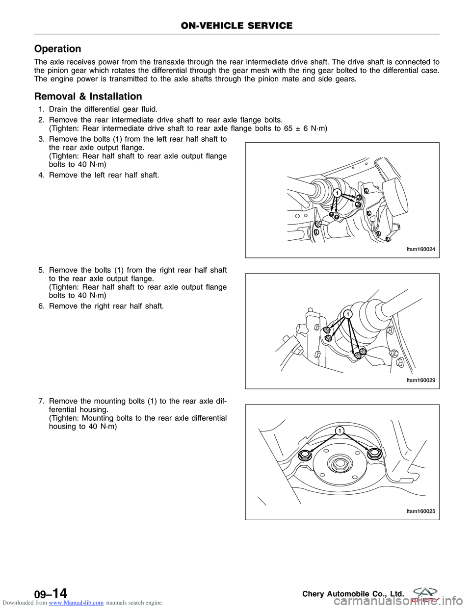
2. Remove the rear intermediate drive shaft to rear axle flange bolts.(Tighten: Rear intermediate drive shaft to rear axle flange bolts to 65 ± 6 N·m)
3. Remove the bolts (1) from the left rear half shaft to the rear axle output flange.
(Tighten: Rear half shaft to rear axle output flange
bolts to 40 N·m)
4. Remove the left rear half shaft.
5. Remove the bolts (1) from the right rear half shaft to the rear axle output flange.
(Tighten: Rear half shaft to rear axle output flange
bolts to 40 N·m)
6. Remove the right rear half shaft.
7. Remove the mounting bolts (1) to the rear axle dif- ferential housing.
(Tighten: Mounting bolts to the rear axle differential
housing to 40 N·m)
ON-VEHICLE SERVICE
LTSM160024
LTSM160029
LTSM160025
09–14Chery Automobile Co., Ltd.