Page 1472 of 1903

Downloaded from www.Manualslib.com manuals search engine Antilock Brake System (ABS) Hydraulic Control Module
Removal & Installation
NOTE :
The following special tools are required to perform the repair procedure:
•Diagnostic Scan Tool X-431
NOTE :
The ABS hydraulic control module is comprised of the Hydraulic Control Unit (HCU) and the Electronic Control Unit
(ECU). These are serviced as a complete unit and cannot be serviced separately. 1. Disconnect the negative battery cable.
2. Turn the ignition switch off.
3. Using a brake pedal holding tool, depress the brake pedal past its first 25 mm of travel and hold it in this posi- tion. This will isolate the master cylinder from the brake hydraulic system and will not allow the brake fluid to
drain out of the master cylinder reservoir while the lines are disconnected.
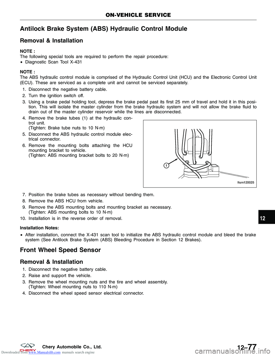
4. Remove the brake tubes (1) at the hydraulic con- trol unit.
(Tighten: Brake tube nuts to 10 N·m)
5. Disconnect the ABS hydraulic control module elec- trical connector.
6. Remove the mounting bolts attaching the HCU mounting bracket to vehicle.
(Tighten: ABS mounting bracket bolts to 20 N·m)
7. Position the brake tubes as necessary without bending them.
8. Remove the ABS HCU from vehicle.
9. Remove the ABS mounting bolts and mounting bracket as necessary. (Tighten: ABS mounting bolts to 10 N·m)
10. Installation is in the reverse order of removal.
Installation Notes:
• After installation, connect the X-431 scan tool to initialize the ABS hydraulic control module and bleed the brake
system (See Antilock Brake System (ABS) Bleeding Procedure in Section 12 Brakes).
Front Wheel Speed Sensor
Removal & Installation
1. Disconnect the negative battery cable.
2. Raise and support the vehicle.
3. Remove the wheel mounting nuts and the tire and wheel assembly.
(Tighten: Wheel mounting nuts to 110 N·m)
4. Disconnect the wheel speed sensor electrical connector.
ON-VEHICLE SERVICE
LTSM120025
12
12–77Chery Automobile Co., Ltd.
Page 1502 of 1903

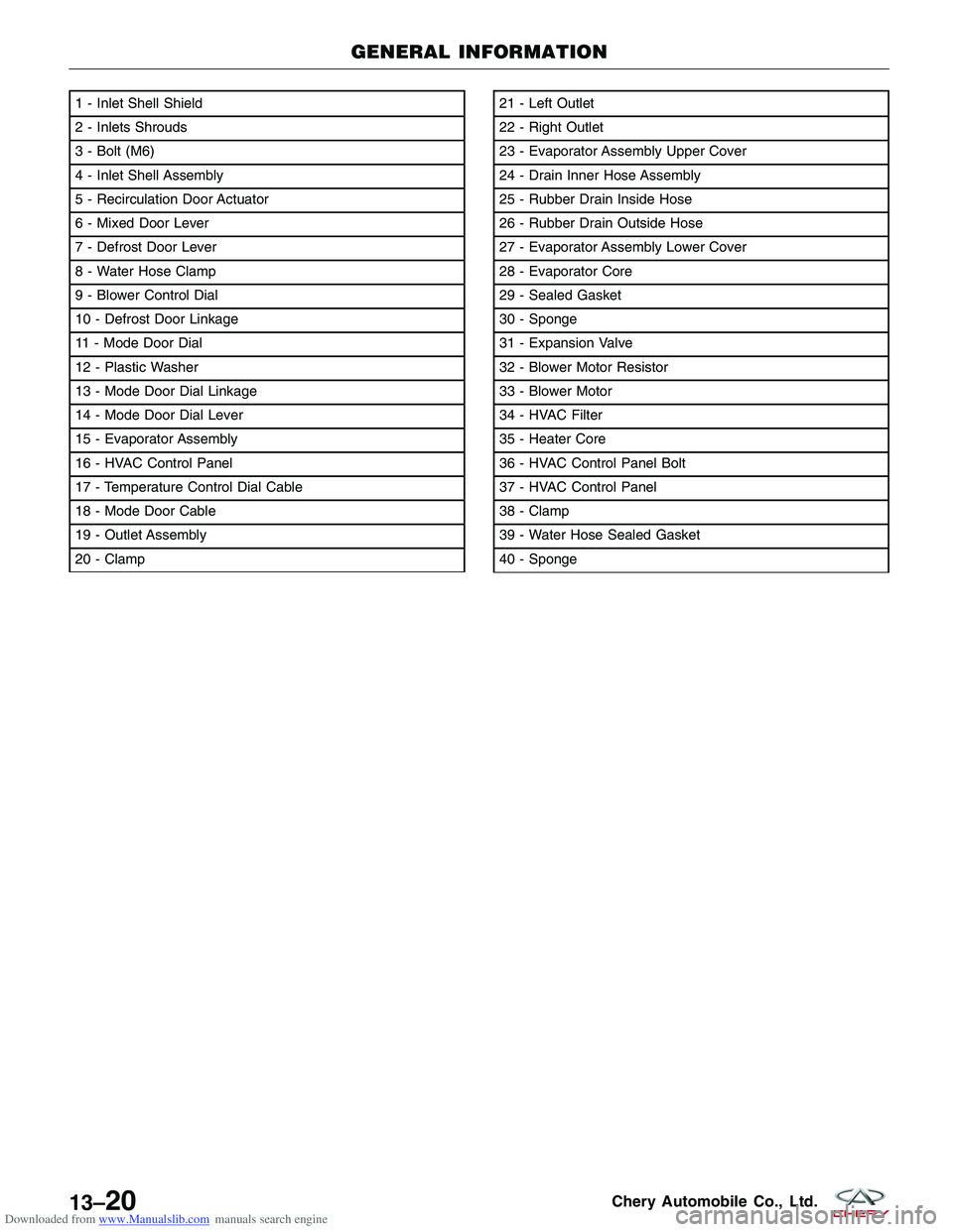
Downloaded from www.Manualslib.com manuals search engine 1 - Inlet Shell Shield
2 - Inlets Shrouds
3 - Bolt (M6)
4 - Inlet Shell Assembly
5 - Recirculation Door Actuator
6 - Mixed Door Lever
7 - Defrost Door Lever
8 - Water Hose Clamp
9 - Blower Control Dial
10 - Defrost Door Linkage
11 - Mode Door Dial
12 - Plastic Washer
13 - Mode Door Dial Linkage
14 - Mode Door Dial Lever
15 - Evaporator Assembly
16 - HVAC Control Panel
17 - Temperature Control Dial Cable
18 - Mode Door Cable
19 - Outlet Assembly
20 - Clamp21 - Left Outlet
22 - Right Outlet
23 - Evaporator Assembly Upper Cover
24 - Drain Inner Hose Assembly
25 - Rubber Drain Inside Hose
26 - Rubber Drain Outside Hose
27 - Evaporator Assembly Lower Cover
28 - Evaporator Core
29 - Sealed Gasket
30 - Sponge
31 - Expansion Valve
32 - Blower Motor Resistor
33 - Blower Motor
34 - HVAC Filter
35 - Heater Core
36 - HVAC Control Panel Bolt
37 - HVAC Control Panel
38 - Clamp
39 - Water Hose Sealed Gasket
40 - Sponge
GENERAL INFORMATION
LTSM130019
13–20Chery Automobile Co., Ltd.
Page 1511 of 1903
Downloaded from www.Manualslib.com manuals search engine ON-VEHICLE SERVICE
HVAC Housing
Removal & Installation
1. Evacuate the A/C system (See A/C System Evacuation and Recharge in Section 13 Heating & Air Conditioning).
2. Drain the cooling system and then disconnectheater hoses (1). (See Cooling System Draining &
Filling in Section 06 Cooling).
3. Remove the instrument panel (See Instrument Panel Removal & Installation in Section 15 Body & Accessories).
4. Remove the evaporator assembly upper retaining bolts (1).
LTSM130010
LTSM130011
13
13–29Chery Automobile Co., Ltd.
Page 1529 of 1903

Downloaded from www.Manualslib.com manuals search engine Heater Core
Description
The heater core is located in the HVAC housing. The heater core is a heat exchanger made of rows of tubes with
fins and is positioned within the air distribution housing so that only the selected amount of air entering the housing
passes through the heater core before it is distributed through the heating-A/C system ducts and outlets. One end of
the heater core is fitted with a tank that includes the fittings for the heater core tubes. The heater core can only be
serviced by removing the HVAC housing from the vehicle.
Operation
Engine coolant is circulated through the heater hoses to the heater core at all times. As the coolant flows through the
heater core, heat is removed from the engine and is transferred to the heater core tubes and fins. Air directed
through the heater core picks up the heat from the heater core fins. The blend-air door allows control of the heater
output air temperature by regulating the amount of air flowing through the heater core. The blower motor speed con-
trols the volume of air flowing through the HVAC housing.
Removal & Installation
1. Drain the cooling system (See Cooling System Draining Procedure in Section 06 Cooling System).
2. Evacuate the A/C system (See A/C System Evacuation and Recharge in Section 13 Heating & Air Conditioning).
3. Remove the HVAC housing assembly and place it on a workbench (See HVAC Housing Removal & Installationin Section 13 Heating & Air Conditioning).
4. Remove the retaining bolts and clamps.
5. Remove the heater core.
6. Installation is in the reverse order of removal.
Installation Notes:
• Verify the cooling system is filled to proper specifications.
ON-VEHICLE SERVICE
13
13–47Chery Automobile Co., Ltd.
Page 1825 of 1903

Downloaded from www.Manualslib.com manuals search engine Front Wiper Link
Removal & Installation
1. Disconnect the negative battery cable.
2. Remove the left lower trim panel of the front wind-shield.
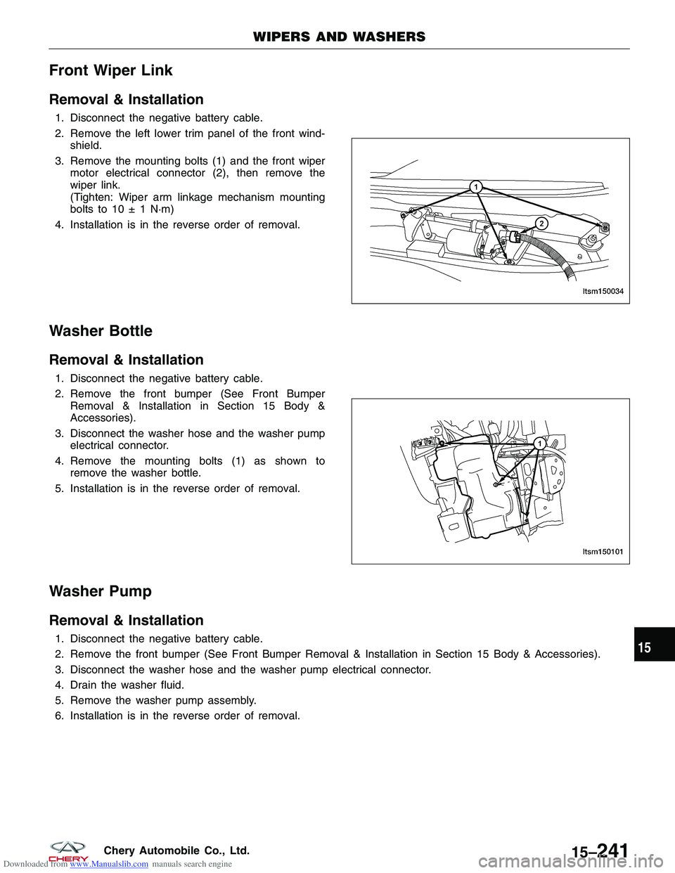
3. Remove the mounting bolts (1) and the front wiper motor electrical connector (2), then remove the
wiper link.
(Tighten: Wiper arm linkage mechanism mounting
bolts to 10 ± 1 N·m)
4. Installation is in the reverse order of removal.
Washer Bottle
Removal & Installation
1. Disconnect the negative battery cable.
2. Remove the front bumper (See Front Bumper Removal & Installation in Section 15 Body &
Accessories).
3. Disconnect the washer hose and the washer pump electrical connector.
4. Remove the mounting bolts (1) as shown to remove the washer bottle.
5. Installation is in the reverse order of removal.
Washer Pump
Removal & Installation
1. Disconnect the negative battery cable.
2. Remove the front bumper (See Front Bumper Removal & Installation in Section 15 Body & Accessories).
3. Disconnect the washer hose and the washer pump electrical connector.
4. Drain the washer fluid.
5. Remove the washer pump assembly.
6. Installation is in the reverse order of removal.
WIPERS AND WASHERS
LTSM150034
LTSM150101
15
15–241Chery Automobile Co., Ltd.