Page 1293 of 1903

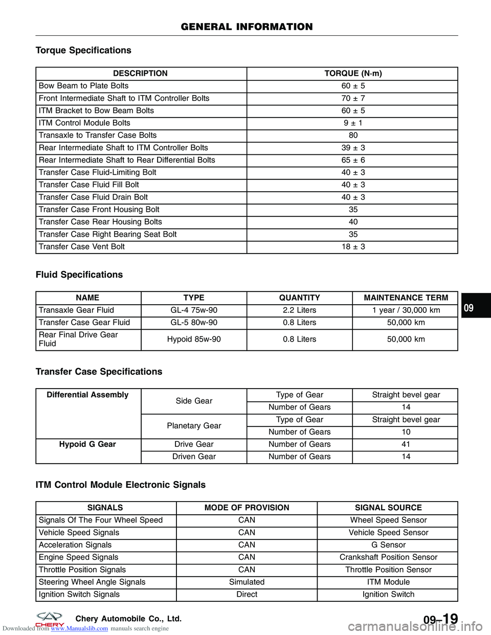
Downloaded from www.Manualslib.com manuals search engine Torque Specifications
DESCRIPTIONTORQUE (N·m)
Bow Beam to Plate Bolts 60 ± 5
Front Intermediate Shaft to ITM Controller Bolts 70 ± 7
ITM Bracket to Bow Beam Bolts 60 ± 5
ITM Control Module Bolts 9 ± 1
Transaxle to Transfer Case Bolts 80
Rear Intermediate Shaft to ITM Controller Bolts 39 ± 3
Rear Intermediate Shaft to Rear Differential Bolts 65 ± 6
Transfer Case Fluid-Limiting Bolt 40 ± 3
Transfer Case Fluid Fill Bolt 40 ± 3
Transfer Case Fluid Drain Bolt 40 ± 3
Transfer Case Front Housing Bolt 35
Transfer Case Rear Housing Bolts 40
Transfer Case Right Bearing Seat Bolt 35
Transfer Case Vent Bolt 18 ± 3
Fluid Specifications
NAMETYPEQUANTITYMAINTENANCE TERM
Transaxle Gear Fluid GL-4 75w-902.2 Liters1 year / 30,000 km
Transfer Case Gear Fluid GL-5 80w-900.8 Liters50,000 km
Rear Final Drive Gear
Fluid Hypoid 85w-90
0.8 Liters50,000 km
Transfer Case Specifications
Differential Assembly
Side GearType of Gear Straight bevel gear
Number of Gears 14
Planetary Gear Type of Gear
Straight bevel gear
Number of Gears 10
Hypoid G Gear Drive GearNumber of Gears 41
Driven Gear Number of Gears 14
ITM Control Module Electronic Signals
SIGNALSMODE OF PROVISION SIGNAL SOURCE
Signals Of The Four Wheel Speed CANWheel Speed Sensor
Vehicle Speed Signals CANVehicle Speed Sensor
Acceleration Signals CANG Sensor
Engine Speed Signals CANCrankshaft Position Sensor
Throttle Position Signals CANThrottle Position Sensor
Steering Wheel Angle Signals SimulatedITM Module
Ignition Switch Signals DirectIgnition Switch
GENERAL INFORMATION
09
09–19Chery Automobile Co., Ltd.
Page 1320 of 1903
Downloaded from www.Manualslib.com manuals search engine 12. Remove the exhaust pipe assembly (See Exhaust Pipe Removal & Installation in Section 07 Exhaust).
13. Remove the high pressure and low pressure lines(1) from the steering gear (drain steering fluid from
lines).
(Tighten: High pressure line to power steering
pump 27 - 33 N·m)
(Tighten: Low pressure line to power steering pump
27 - 33 N·m)
14. Remove the two bolts (1) between the steering gearing and the sub-frame.
(Tighten: Steering gear to sub-frame bolts to 70 -
80 N·m)
ON-VEHICLE SERVICE
LTSM110007
LTSM100024
10
10–19Chery Automobile Co., Ltd.
Page 1389 of 1903
Downloaded from www.Manualslib.com manuals search engine ON-VEHICLE SERVICE
Power Steering Pump - 1.6L & 1.8L & 2.0L
Removal & Installation
1. Siphon as much steering fluid as possible from the power steering fluid reservoir.
2. Raise and support the vehicle.
3. Remove the engine cover.
4. Remove the drive belt (See Accessory Drive Belt Removal & Installation in Section 02 Engine).
5. Remove the high pressure (1) and low pressurelines (2) from the power steering pump (drain
steering fluid from lines).
(Tighten: High pressure line to power steering
pump 40 - 50 N·m)
(Tighten: Low pressure line to power steering pump
40 - 50 N·m)
6. Remove the three power steering pump mounting bolts (1).
(Tighten: Power steering pump bolts to 20 - 30
N·m)
7. Remove the power steering pump.
8. Installation is in the reverse order of removal.
BESM110011
LTSM110045
11 –34Chery Automobile Co., Ltd.
Page 1390 of 1903
Downloaded from www.Manualslib.com manuals search engine Power Steering Pump - 2.4L
Removal & Installation
1. Siphon out as much power steering fluid as possible from the reservoir.
2. Raise and support the vehicle.
3. Remove the return hose clamp (1) from the steer-ing liquid reservoir and insert the end of the hose
into a container.
4. Start the engine and turn the steering wheel from lock-to-lock until all power steering fluid has been drained from the system.
5. Stop the engine.
6. Remove the engine lower shield.
7. Loosen the power steering pump belt adjustment bolt (1).
ON-VEHICLE SERVICE
LTSM110042
LTSM020185
11
11 –35Chery Automobile Co., Ltd.
Page 1393 of 1903
Downloaded from www.Manualslib.com manuals search engine 5. Remove the high pressure and low pressure lines(1) from the steering gear (drain steering fluid from
lines).
(Tighten: High pressure line to power steering
pump 27 - 33 N·m)
(Tighten: Low pressure line to power steering pump
27 - 33 N·m)
6. Remove the power steering line clamp bracket bolt (1) from the pressure and return lines.
(Tighten: Power steering line clamp bracket bolt to
10 N·m)
7. Remove the pressure and return lines.
8. Installation is in the reverse order of removal.
Installation Notes:
• Fill the power steering reservoir to the proper level.
• Check the system for leaks.
ON-VEHICLE SERVICE
LTSM110007
BESM110013
11 –38Chery Automobile Co., Ltd.
Page 1402 of 1903

Downloaded from www.Manualslib.com manuals search engine DIAGNOSIS & TESTING
Diagnostic Help
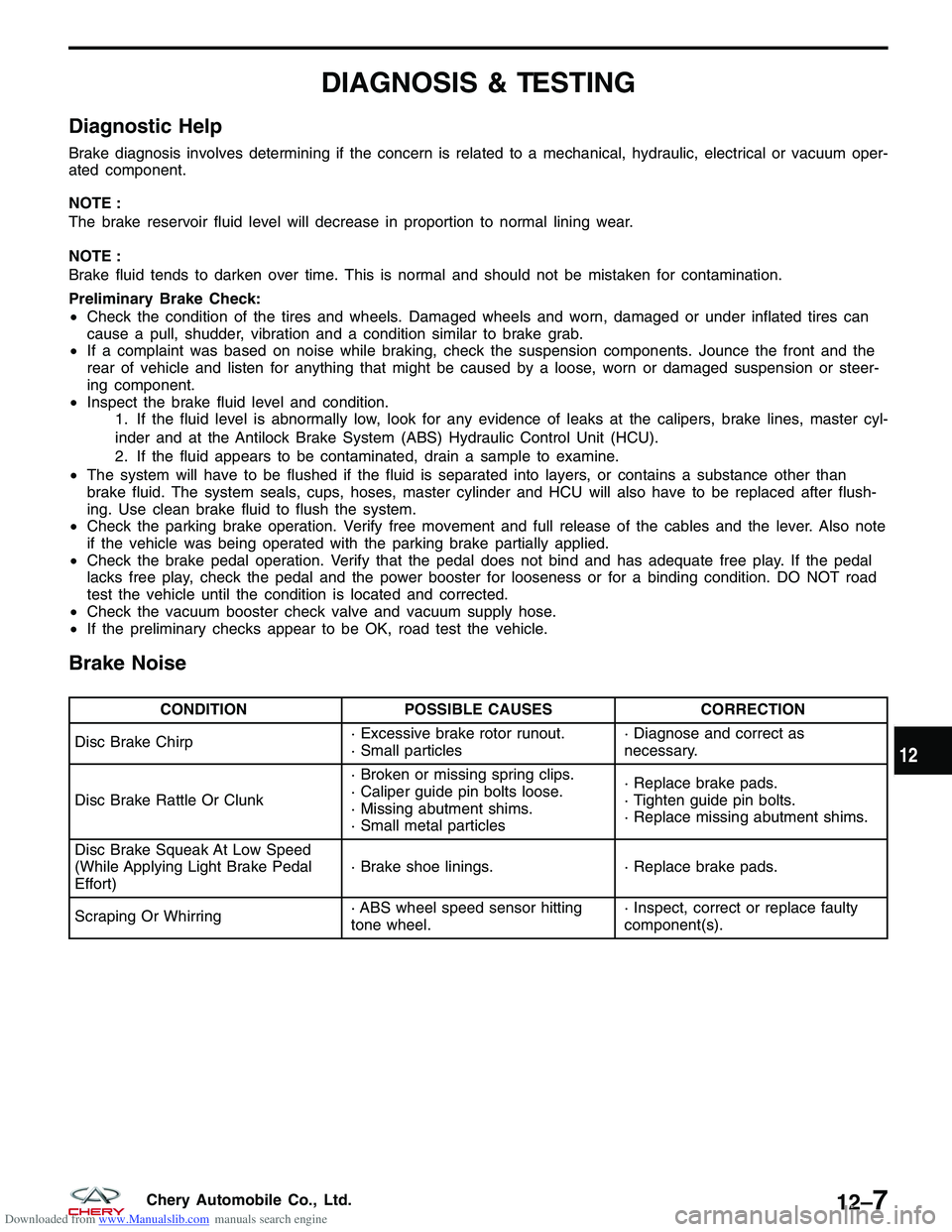
Brake diagnosis involves determining if the concern is related to a mechanical, hydraulic, electrical or vacuum oper-
ated component.
NOTE :
The brake reservoir fluid level will decrease in proportion to normal lining wear.
NOTE :
Brake fluid tends to darken over time. This is normal and should not be mistaken for contamination.
Preliminary Brake Check:
•Check the condition of the tires and wheels. Damaged wheels and worn, damaged or under inflated tires can
cause a pull, shudder, vibration and a condition similar to brake grab.
• If a complaint was based on noise while braking, check the suspension components. Jounce the front and the
rear of vehicle and listen for anything that might be caused by a loose, worn or damaged suspension or steer-
ing component.
• Inspect the brake fluid level and condition.
1. If the fluid level is abnormally low, look for any evidence of leaks at the calipers, brake lines, master cyl-
inder and at the Antilock Brake System (ABS) Hydraulic Control Unit (HCU).
2. If the fluid appears to be contaminated, drain a sample to examine.
• The system will have to be flushed if the fluid is separated into layers, or contains a substance other than
brake fluid. The system seals, cups, hoses, master cylinder and HCU will also have to be replaced after flush-
ing. Use clean brake fluid to flush the system.
• Check the parking brake operation. Verify free movement and full release of the cables and the lever. Also note
if the vehicle was being operated with the parking brake partially applied.
• Check the brake pedal operation. Verify that the pedal does not bind and has adequate free play. If the pedal
lacks free play, check the pedal and the power booster for looseness or for a binding condition. DO NOT road
test the vehicle until the condition is located and corrected.
• Check the vacuum booster check valve and vacuum supply hose.
• If the preliminary checks appear to be OK, road test the vehicle.
Brake Noise
CONDITION POSSIBLE CAUSES CORRECTION
Disc Brake Chirp · Excessive brake rotor runout.
· Small particles· Diagnose and correct as
necessary.
Disc Brake Rattle Or Clunk · Broken or missing spring clips.
· Caliper guide pin bolts loose.
· Missing abutment shims.
· Small metal particles· Replace brake pads.
· Tighten guide pin bolts.
· Replace missing abutment shims.
Disc Brake Squeak At Low Speed
(While Applying Light Brake Pedal
Effort) · Brake shoe linings.
· Replace brake pads.
Scraping Or Whirring · ABS wheel speed sensor hitting
tone wheel.· Inspect, correct or replace faulty
component(s).
12
12–7Chery Automobile Co., Ltd.
Page 1414 of 1903

Downloaded from www.Manualslib.com manuals search engine lining against the inner surface of the disc brake rotor. At the same time, fluid pressure within the piston bore forces
the caliper to slide inward on the slide pins. This action brings the outboard brake pad lining into contact with the
outer surface of the disc brake rotor.
Removal & Installation
1. Using a brake pedal holding tool, depress the brake pedal past its first 25 mm of travel and hold it in this posi-tion. This will isolate the master cylinder from the brake hydraulic system and will not allow the brake fluid to
drain out of the master cylinder reservoir when the lines are opened.
2. Raise and support the vehicle.
3. Remove the wheel mounting nuts and the tire and wheel assembly. (Tighten: Wheel mounting nuts to 110 N·m)
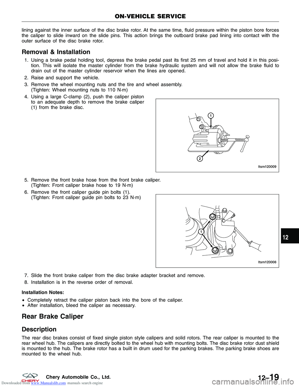
4. Using a large C-clamp (2), push the caliper piston to an adequate depth to remove the brake caliper
(1) from the brake disc.
5. Remove the front brake hose from the front brake caliper. (Tighten: Front caliper brake hose to 19 N·m)
6. Remove the front caliper guide pin bolts (1). (Tighten: Front caliper guide pin bolts to 23 N·m)
7. Slide the front brake caliper from the disc brake adapter bracket and remove.
8. Installation is in the reverse order of removal.
Installation Notes:
• Completely retract the caliper piston back into the bore of the caliper.
• After installation, bleed the caliper as necessary.
Rear Brake Caliper
Description
The rear disc brakes consist of fixed single piston style calipers and solid rotors. The rear caliper is mounted to the
rear wheel hub. The calipers are directly bolted to the wheel hub with mounting bolts. The disc brake rotor dust shield
is mounted to the hub. The brake rotor has a built in drum used for the parking brakes. The parking brake shoes are
mounted to the wheel hub.
ON-VEHICLE SERVICE
LTSM120009
LTSM120008
12
12–19Chery Automobile Co., Ltd.
Page 1415 of 1903

Downloaded from www.Manualslib.com manuals search engine Operation
When the brakes are applied, fluid pressure is exerted against the caliper piston. The fluid pressure is exerted
equally and in all directions. This means pressure exerted against the caliper piston and within the caliper bores will
be equal. Fluid pressure applied to the pistons is transmitted directly to the inboard brake pad. This forces the pad
lining against the inner surface of the brake rotor. At the same time, fluid pressure within the piston bore forces the
caliper to slide inward on the slide pins. This action brings the outboard brake pad lining into contact with the outer
surface of the disc brake rotor.
Removal & Installation
1. Using a brake pedal holding tool, depress the brake pedal past its first 25 mm of travel and hold it in this posi-tion. This will isolate the master cylinder from the brake hydraulic system and will not allow the brake fluid to
drain out of the master cylinder reservoir when the lines are opened.
2. Raise and support the vehicle.
3. Remove the wheel mounting nuts and the tire and wheel assembly. (Tighten: Wheel mounting nuts to 110 N·m)
4. Remove the banjo bolt connecting the brake hose to the rear brake caliper. (Tighten: Rear caliper banjo bolt to 20 N·m)
5. Remove the rear caliper guide pin bolts. (Tighten: Rear caliper guide pin bolts to 23 N·m)
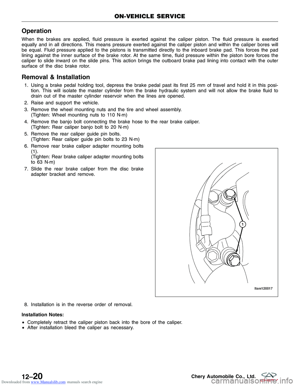
6. Remove rear brake caliper adapter mounting bolts (1).
(Tighten: Rear brake caliper adapter mounting bolts
to 63 N·m)
7. Slide the rear brake caliper from the disc brake adapter bracket and remove.
8. Installation is in the reverse order of removal.
Installation Notes:
• Completely retract the caliper piston back into the bore of the caliper.
• After installation bleed the caliper as necessary.
ON-VEHICLE SERVICE
LTSM120017
12–20Chery Automobile Co., Ltd.