Page 1329 of 1903

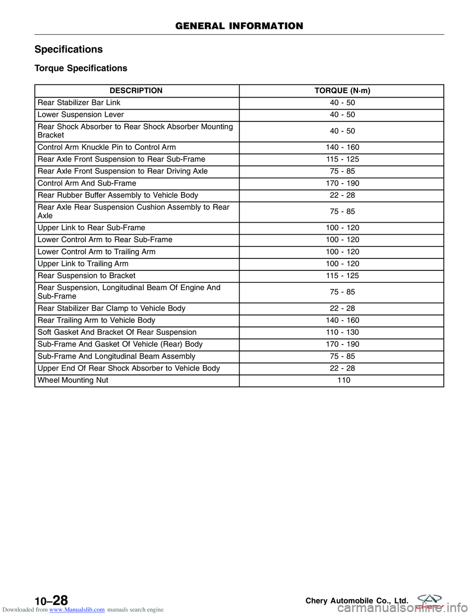
Downloaded from www.Manualslib.com manuals search engine Specifications
Torque Specifications
DESCRIPTIONTORQUE (N·m)
Rear Stabilizer Bar Link 40 - 50
Lower Suspension Lever 40 - 50
Rear Shock Absorber to Rear Shock Absorber Mounting
Bracket 40-50
Control Arm Knuckle Pin to Control Arm 140 - 160
Rear Axle Front Suspension to Rear Sub-Frame 115 - 125
Rear Axle Front Suspension to Rear Driving Axle 75 - 85
Control Arm And Sub-Frame 170 - 190
Rear Rubber Buffer Assembly to Vehicle Body 22 - 28
Rear Axle Rear Suspension Cushion Assembly to Rear
Axle 75-85
Upper Link to Rear Sub-Frame 100 - 120
Lower Control Arm to Rear Sub-Frame 100 - 120
Lower Control Arm to Trailing Arm 100 - 120
Upper Link to Trailing Arm 100 - 120
Rear Suspension to Bracket 115 - 125
Rear Suspension, Longitudinal Beam Of Engine And
Sub-Frame 75-85
Rear Stabilizer Bar Clamp to Vehicle Body 22 - 28
Rear Trailing Arm to Vehicle Body 140 - 160
Soft Gasket And Bracket Of Rear Suspension 110 - 130
Sub-Frame And Gasket Of Vehicle (Rear) Body 170 - 190
Sub-Frame And Longitudinal Beam Assembly 75 - 85
Upper End Of Rear Shock Absorber to Vehicle Body 22 - 28
Wheel Mounting Nut \
11
0
GENERAL INFORMATION
10–28Chery Automobile Co., Ltd.
Page 1330 of 1903
Downloaded from www.Manualslib.com manuals search engine DIAGNOSIS & TESTING
Vehicle Inspection
Inspect the rear axle for the following:
•Check the rear axle for loose bearings.
• Check the rear axle hub for any damage or excessive runout.
Vibration At High Speed
This problem could be a result of the following:
•Foreign material (mud, etc.) packed on the backside of the wheel(s).
• Out of balance tires or wheels.
• Improper tire or wheel runout.
10
10–29Chery Automobile Co., Ltd.
Page 1331 of 1903
Downloaded from www.Manualslib.com manuals search engine ON-VEHICLE SERVICE
Rear Lower Control Arm
Removal & Installation
1. Raise and support the vehicle.
2. Remove the bolt that joins rear stabilizer bar and rear suspension lower control arm (See Rear Stabilizer BarLink Removal & Installation in Section 10 Suspension).
3. Remove the retaining bolt (1) connecting the lower control arm and rear trailing arm.
(Tighten: Lower control arm to rear trailing arm bolt
to 80 - 100 N·m)
4. Remove the retaining bolt (1) connecting the upper control arm and rear sub-frame assembly.
(Tighten: Upper control arm and rear sub-frame
assembly bolt to 80 - 100 N·m)
5. Installation is in the reverse order of removal.
Installation Notes:
• After installation, each bolt must be tightened to the
required tightening torque.
LTSM100061
LTSM100066
10–30Chery Automobile Co., Ltd.
Page 1332 of 1903
Downloaded from www.Manualslib.com manuals search engine Rear Upper Control Arm
Removal & Installation
1. Raise and support the vehicle.
2. Remove the retaining bolt (1) connecting the uppercontrol arm and rear trailing arm.
(Tighten: Upper control arm to rear trailing arm bolt
to 80 - 100 N·m)
3. Remove the retaining bolt (1) connecting the upper control arm and rear sub-frame assembly.
(Tighten: Upper control arm to rear sub-frame
assembly bolt to 80 - 100 N·m)
4. Installation is in the reverse order of removal.
Installation Notes:
• After installation, each bolt must be tightened to the
required tightening torque.
ON-VEHICLE SERVICE
LTSM100068
LTSM10006510
10–31Chery Automobile Co., Ltd.
Page 1333 of 1903

Downloaded from www.Manualslib.com manuals search engine Rear Stabilizer Bar Link
Removal & Installation
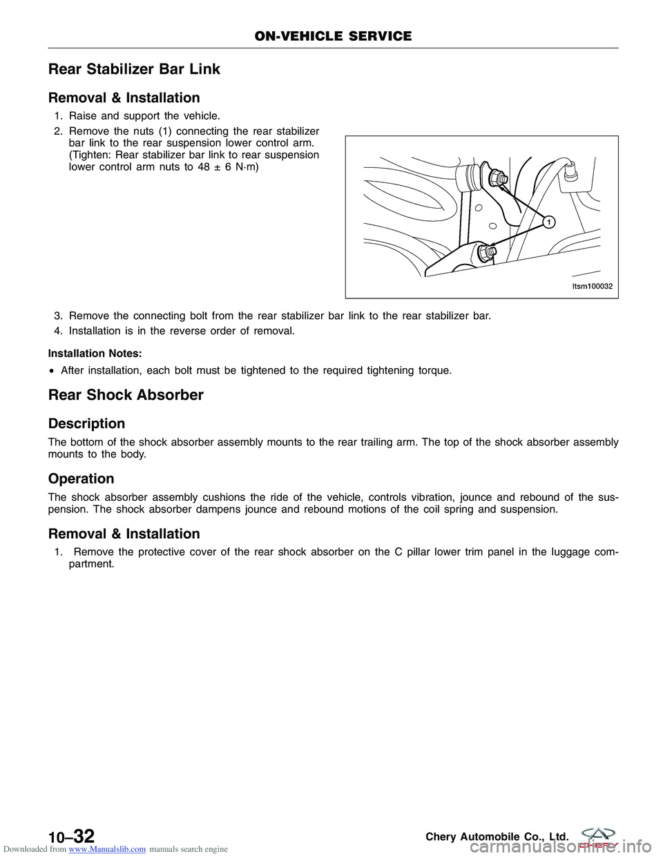
1. Raise and support the vehicle.
2. Remove the nuts (1) connecting the rear stabilizerbar link to the rear suspension lower control arm.
(Tighten: Rear stabilizer bar link to rear suspension
lower control arm nuts to 48 ± 6 N·m)
3. Remove the connecting bolt from the rear stabilizer bar link to the rear stabilizer bar.
4. Installation is in the reverse order of removal.
Installation Notes:
• After installation, each bolt must be tightened to the required tightening torque.
Rear Shock Absorber
Description
The bottom of the shock absorber assembly mounts to the rear trailing arm. The top of the shock absorber assembly
mounts to the body.
Operation
The shock absorber assembly cushions the ride of the vehicle, controls vibration, jounce and rebound of the sus-
pension. The shock absorber dampens jounce and rebound motions of the coil spring and suspension.
Removal & Installation
1. Remove the protective cover of the rear shock absorber on the C pillar lower trim panel in the luggage com-
partment.
ON-VEHICLE SERVICE
LTSM100032
10–32Chery Automobile Co., Ltd.
Page 1334 of 1903

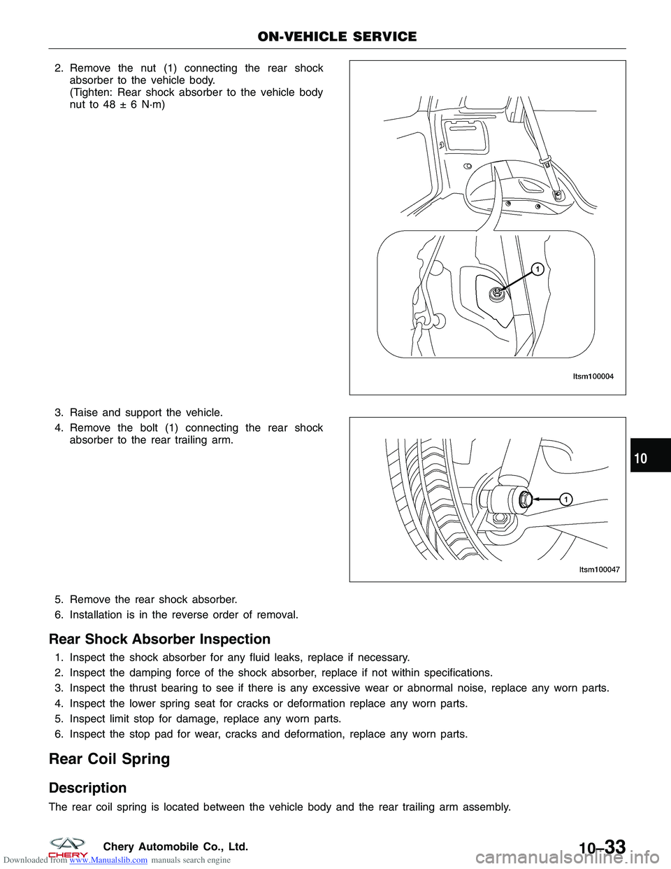
Downloaded from www.Manualslib.com manuals search engine 2. Remove the nut (1) connecting the rear shockabsorber to the vehicle body.
(Tighten: Rear shock absorber to the vehicle body
nut to 48 ± 6 N·m)
3. Raise and support the vehicle.
4. Remove the bolt (1) connecting the rear shock absorber to the rear trailing arm.
5. Remove the rear shock absorber.
6. Installation is in the reverse order of removal.
Rear Shock Absorber Inspection
1. Inspect the shock absorber for any fluid leaks, replace if necessary.
2. Inspect the damping force of the shock absorber, replace if not within specifications.
3. Inspect the thrust bearing to see if there is any excessive wear or abnormal noise, replace any worn parts.
4. Inspect the lower spring seat for cracks or deformation replace any worn parts.
5. Inspect limit stop for damage, replace any worn parts.
6. Inspect the stop pad for wear, cracks and deformation, replace any worn parts.
Rear Coil Spring
Description
The rear coil spring is located between the vehicle body and the rear trailing arm assembly.
ON-VEHICLE SERVICE
LTSM100004
LTSM100047
10
10–33Chery Automobile Co., Ltd.
Page 1335 of 1903
Downloaded from www.Manualslib.com manuals search engine Operation
Coil springs are designed to store energy and subsequently release it, and to absorb shock and maintain a force
between contacting surfaces. Coil springs are rated for specific vehicle applications.
Removal & Installation
1. Raise and support the vehicle.
2. Remove the wheel mounting nuts and the wheel assembly.(Tighten: Wheel mounting nuts to 110 N·m)
3. Use a jack to support the rear trailing arm.
4. Remove the retaining bolt (1) that connects the lower control arm to rear trailing arm.
(Tighten: Lower control arm to rear trailing arm bolt
to 80-100 N·m)
5. Remove the bolt (1) connecting the rear shock absorber to the rear trailing arm.
6. Release the jack slowly.
7. Remove the coil spring.
8. Installation is in the reverse order of removal.
ON-VEHICLE SERVICE
LTSM100061
LTSM100047
10–34Chery Automobile Co., Ltd.
Page 1336 of 1903
Downloaded from www.Manualslib.com manuals search engine Rear Trailing Arm Assembly
Removal & Installation
1. Raise and support the vehicle.
2. Remove the wheel mounting nuts and the wheel assembly.(Tighten: Wheel mounting nuts to 110 N·m)
3. Use a jack to support the rear trailing arm.
4. Remove the connecting bolts (1) that joins the rear trailing arm and the shock absorber bracket.
(Tighten: Rear trailing arm to shock absorber
bracket bolts to 80 - 100 N·m)
5. Lower the jack and remove the rear spring.
6. Remove the connecting bolt that joins the rear trailing arm to the upper control arm (See Rear Upper Control Arm Removal & installation in Section 10 Suspension).
7. Remove the connecting bolt that joins the rear trailing arm to the lower control arm (See Rear Lower Control Arm Removal & installation in Section 10 Suspension).
ON-VEHICLE SERVICE
LTSM100060
10
10–35Chery Automobile Co., Ltd.