Page 1297 of 1903
Downloaded from www.Manualslib.com manuals search engine Interactive Torque Management (ITM) Control Module
Description
The ITM control module is located under the driver seat.
Operation
The ITM control module collects signals from the Engine Control Module (ECM) and Antilock Brake System (ABS)
controller, judges the vehicle driving state, controls the working electric current of the ITM controller and distributes
the torque of the front axle and the rear axle intelligently according to such signals.
Removal & Installation
1. Disconnect the negative battery cable.
2. Adjust the left front seat fully backward.
3. Remove the ITM control module mounting bolts.
4. Remove the ITM control module electrical connec-tor.
5. Remove the ITM control module (1).
6. Installation is in the reverse order of removal.
ON-VEHICLE SERVICE
LTSM16002809
09–23Chery Automobile Co., Ltd.
Page 1298 of 1903
Downloaded from www.Manualslib.com manuals search engine DRIVE SHAFT (4X4)
GENERAL INFORMATION09-25
Description 09-25
Operation 09-25
Specifications 09-25
DIAGNOSIS & TESTING09-26
Vehicle Inspection 09-26
Shudder Or Vibration During Acceleration 09-26
Clunking Noise During Acceleration 09-26 Shudder Or Vibration During Acceleration 09-26
Vibration At High Speeds 09-26
ON-VEHICLE SERVICE09-27
Front Intermediate Drive Shaft 09-27
Removal & Installation 09-27
Rear Intermediate Drive Shaft 09-27
Removal & Installation 09-27
09–24Chery Automobile Co., Ltd.
Page 1299 of 1903
Downloaded from www.Manualslib.com manuals search engine GENERAL INFORMATION
Description
The drive shafts for the 4x4 are separated into the front intermediate drive shaft and the rear intermediate drive shaft.
The front intermediate drive shaft is installed between the transfer case and the Interactive Torque Management
(ITM) controller. The rear intermediate drive shaft is installed between the ITM controller and the rear axle.
Operation
The drive shafts transfer the torque from the transaxle to the rear axle.
Specifications
Torque Specifications
DESCRIPTIONTORQUE (N·m)
Front Intermediate Drive Shaft to ITM Controller Bolts 70 ± 7
Rear Intermediate Drive Shaft to ITM Controller Bolts 39 ± 3
Rear Intermediate Drive Shaft to Body Bolts 60 ± 5
Rear Intermediate Drive Shaft to Rear Axle Flange 65 ± 6
09
09–25Chery Automobile Co., Ltd.
Page 1300 of 1903
Downloaded from www.Manualslib.com manuals search engine DIAGNOSIS & TESTING
Vehicle Inspection
Inspect the drive shaft for the following:
•Check the drive shaft for loose bearings.
• Check the drive shaft for any damage or excessive runout.
Shudder Or Vibration During Acceleration
This problem could be a result of:
•A worn or damaged drive shaft joint.
• Improper wheel alignment.
Clunking Noise During Acceleration
This noise may be a result of one of the following conditions:
•A worn drive shaft assembly.
• A loose drive shaft assembly.
• A damaged or worn drive shaft joint.
Shudder Or Vibration During Acceleration
This problem could be a result of:
•A worn or damaged drive shaft joint.
• Improper wheel alignment.
Vibration At High Speeds
This problem could be a result of:
•Foreign material (mud, etc.) packed on the backside of the wheel(s).
• Out of balance tires or wheels.
• Improper tire or wheel runout.
09–26Chery Automobile Co., Ltd.
Page 1301 of 1903

Downloaded from www.Manualslib.com manuals search engine ON-VEHICLE SERVICE
Front Intermediate Drive Shaft
Removal & Installation
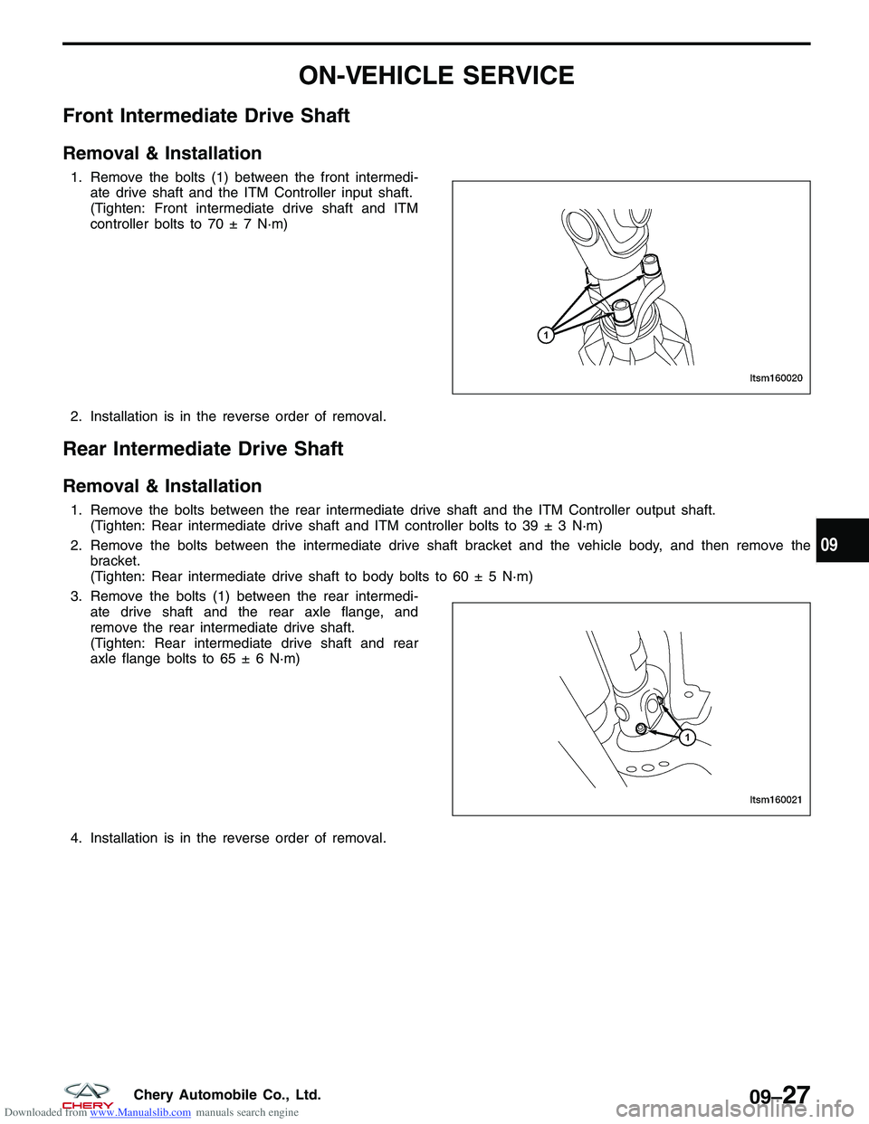
1. Remove the bolts (1) between the front intermedi-ate drive shaft and the ITM Controller input shaft.
(Tighten: Front intermediate drive shaft and ITM
controller bolts to 70 ± 7 N·m)
2. Installation is in the reverse order of removal.
Rear Intermediate Drive Shaft
Removal & Installation
1. Remove the bolts between the rear intermediate drive shaft and the ITM Controller output shaft. (Tighten: Rear intermediate drive shaft and ITM controller bolts to 39 ± 3 N·m)
2. Remove the bolts between the intermediate drive shaft bracket and the vehicle body, and then remove the bracket.
(Tighten: Rear intermediate drive shaft to body bolts to 60 ± 5 N·m)
3. Remove the bolts (1) between the rear intermedi- ate drive shaft and the rear axle flange, and
remove the rear intermediate drive shaft.
(Tighten: Rear intermediate drive shaft and rear
axle flange bolts to 65 ± 6 N·m)
4. Installation is in the reverse order of removal.
LTSM160020
LTSM160021
09
09–27Chery Automobile Co., Ltd.
Page 1302 of 1903

Downloaded from www.Manualslib.com manuals search engine SUSPENSION
10
CONTENTSpage
Front Suspension ..................................................................... 10-1
Rear Suspension .................................................................... 10-25
Alignment ........................................................................\
.. 10-38
Wheels and Tires ................................................................... 10-47
FRONT SUSPENSION
GENERAL INFORMATION10-2
Description 10-2
Operation 10-4
Specifications 10-4
Special Tools 10-5
DIAGNOSIS & TESTING10-6
Vehicle Suspension Troubleshooting Chart 10-6
ON-VEHICLE SERVICE10-7
Front Steering Knuckle 10-7
Description 10-7
Operation 10-7
Removal & Installation 10-7
Front Lower Control Arm 10-9
Description 10-9
Operation 10-9
Removal & Installation 10-9
Front Stabilizer Bar Link 10-11
Removal & Installation 10-11Front Stabilizer Bar
10-12
Removal & Installation 10-12
Front Strut Assembly 10-13
Description 10-13
Operation 10-14
Diagnosis & Testing 10-14
Removal & Installation 10-14
Front Coil Spring 10-16
Description 10-16
Operation 10-16
Removal & Installation 10-16
Front Sub-Frame Assembly 10-17
Removal & Installation 10-17
UNIT REPAIR10-21
Front Strut 10-21
Disassemble 10-21
Inspection 10-22
Strut Disposal Procedure 10-22
Assembly 10-23
10
10–1Chery Automobile Co., Ltd.
Page 1303 of 1903
Downloaded from www.Manualslib.com manuals search engine GENERAL INFORMATION
Description
The front suspension system incorporates a strut assembly that takes the place of the upper control arm and upper
ball joint. The strut carries out the function of a shock absorber and is encompassed by a coil spring. The strut
assembly supports the weight of the vehicle and is also the pivot point for the steering knuckle. This system uses a
lower control arm and ball joint for the lower pivot point of the steering knuckle.
10–2Chery Automobile Co., Ltd.
Page 1304 of 1903
Downloaded from www.Manualslib.com manuals search engine The front suspension consists of the following components:
GENERAL INFORMATION
LTSM100008
10
10–3Chery Automobile Co., Ltd.