Page 1305 of 1903
Downloaded from www.Manualslib.com manuals search engine WARNING!
Do not remove the strut rod nut while the strut assembly is installed in the vehicle, or before the coil spring is
compressed with a spring compressor. The spring is held under high pressure and must be compressed before
the strut rod nut can be removed.
CAUTION:
At no time when servicing a vehicle can a sheet metal screw, bolt, or other metal fastener be
installed in the shock tower to replace the original plastic clamp. It may come in contact with the
strut or coil spring.
CAUTION:
The wheel bearing will be damaged if the vehicle is rolled with the axle shaft hub nut loose.
Operation
The front suspension utilizes a MacPherson strut system. This suspension system incorporates a strut assembly that
takes the place of the upper arm and ball joint. The strut performs the function of a shock absorber and is encom-
passed by a coil spring.
Specifications
Torque Specifications
DESCRIPTIONTORQUE (N·m)
Connecting Rod And Front Stabilizer Bar 40 - 50
Connect The Right And Left Assembly Of Front Drive
Shaft With Brake Disc 260 - 270
Control Arm And Sub-Frame 170 - 190
Connect Intermediate Propeller Shaft With Vehicle Body 58 - 68
Connecting Rod With Lower Suspension Lever 40 - 50
Connect Control Arm Knuckle Pin With Knuckle
Assembly 110 - 130
Connect Control Arm Knuckle Pin With Control Arm 140 - 160
Front Connecting Rod And Front Shock Absorber 40 - 50
Front Axle Shaft Nut 135
Fix Stabilizer Bar Clamp To Sub-Frame 22 - 28
Front Shock Absorber and Coil Spring 100 - 120
Front Suspension Strut And Vehicle Body 45 - 55
Front Suspension And Bracket 75 - 85
Insert From The Lower Part Of Sub-Frame, And The
Bolt Is On The Suspension. The Middle Part Shall Be
Clamped To The Main Longitudinal Beam Of Engine 110 - 130
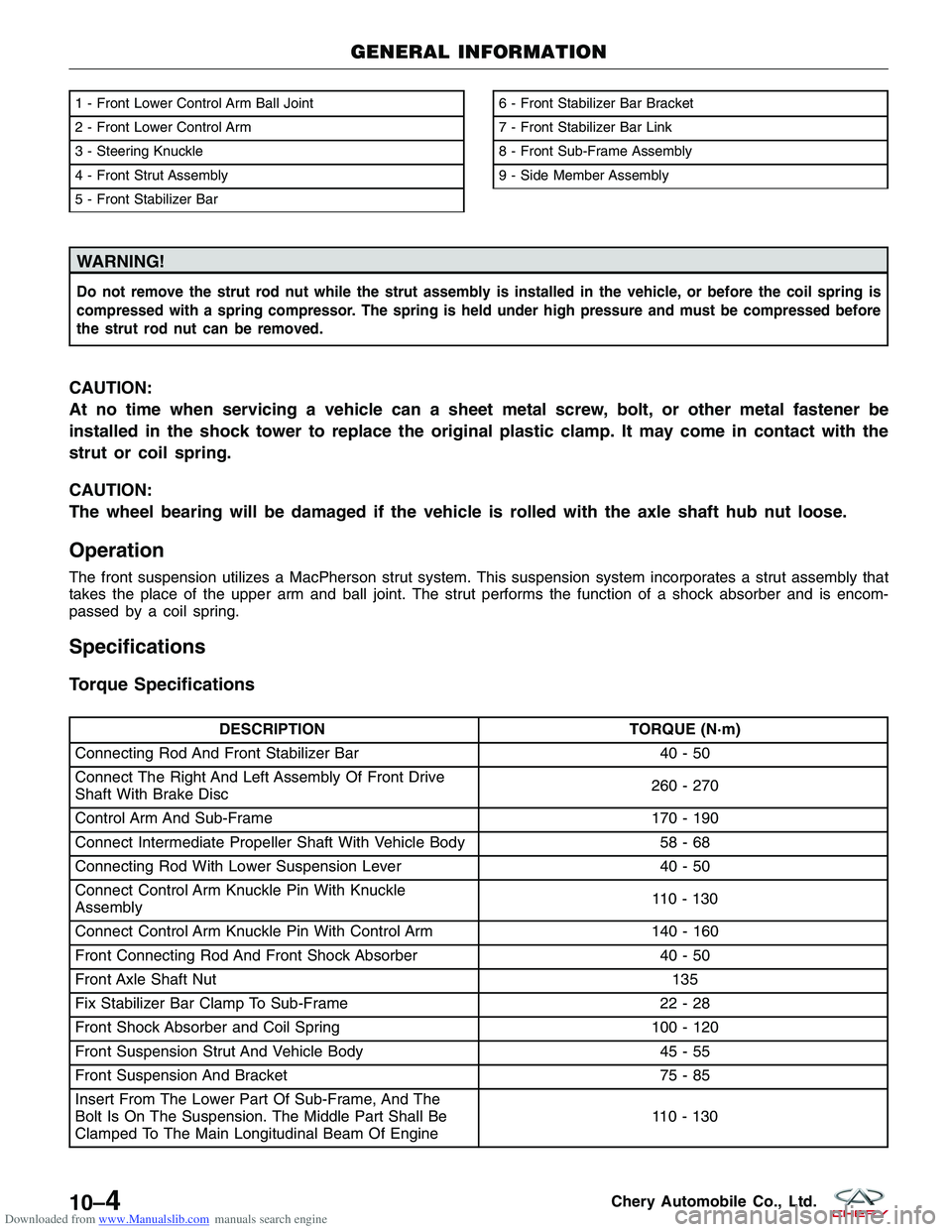
1 - Front Lower Control Arm Ball Joint
2 - Front Lower Control Arm
3 - Steering Knuckle
4 - Front Strut Assembly
5 - Front Stabilizer Bar6 - Front Stabilizer Bar Bracket
7 - Front Stabilizer Bar Link
8 - Front Sub-Frame Assembly
9 - Side Member Assembly
GENERAL INFORMATION
LTSM100008
10–4Chery Automobile Co., Ltd.
Page 1306 of 1903
Downloaded from www.Manualslib.com manuals search engine DESCRIPTIONTORQUE (N·m)
Longitudinal Beam And Flat Gasket Of Vehicle (Front)
Body 74-86
One On Each Side To Connect Upper Link With Towing
Arm 100 - 120
One On Each Side To Connect Lower Control Arm With
Towing Arm 100 - 120
Steering Knuckle And Suspension Strut 110 - 130
Soft Gasket And Bracket Of Front Suspension 75 - 85
Steering Knuckle Tie Rod And Steering Knuckle 32 - 38
Sub-Frame And Gasket Of Vehicle (Front) Body 170 - 190
Sub-Frame And Longitudinal Beam Welding Assembly 75 - 85
Steering Gear And Sub-Frame 75 - 85
Wheel Mounting Nut \
\
110
Special Tools
Ball Joint Separator
CH-10002
GENERAL INFORMATION
10
10–5Chery Automobile Co., Ltd.
Page 1307 of 1903
Downloaded from www.Manualslib.com manuals search engine DIAGNOSIS & TESTING
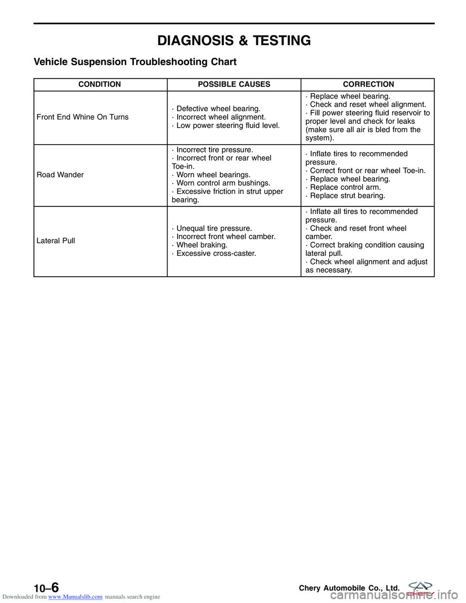
Vehicle Suspension Troubleshooting Chart
CONDITIONPOSSIBLE CAUSES CORRECTION
Front End Whine On Turns · Defective wheel bearing.
· Incorrect wheel alignment.
· Low power steering fluid level.· Replace wheel bearing.
· Check and reset wheel alignment.
· Fill power steering fluid reservoir to
proper level and check for leaks
(make sure all air is bled from the
system).
Road Wander · Incorrect tire pressure.
· Incorrect front or rear wheel
Toe-in.
· Worn wheel bearings.
· Worn control arm bushings.
· Excessive friction in strut upper
bearing.· Inflate tires to recommended
pressure.
· Correct front or rear wheel Toe-in.
· Replace wheel bearing.
· Replace control arm.
· Replace strut bearing.
Lateral Pull · Unequal tire pressure.
· Incorrect front wheel camber.
· Wheel braking.
· Excessive cross-caster.· Inflate all tires to recommended
pressure.
· Check and reset front wheel
camber.
· Correct braking condition causing
lateral pull.
· Check wheel alignment and adjust
as necessary.
10–6Chery Automobile Co., Ltd.
Page 1308 of 1903
Downloaded from www.Manualslib.com manuals search engine ON-VEHICLE SERVICE
Front Steering Knuckle
Description
The steering knuckle is a single casting with legs machined for attachment to the front strut assembly on the top and
steering linkage on the trailing leading end. The steering knuckle also has two machined, drilled legs on the end
casting to support and align the front disc brake caliper adapter.
Operation
The steering knuckle supports the hub and bearing. The front suspension steering knuckle is not a repairable com-
ponent of the front suspension. It must be replaced if damaged in any way. If it is determined that the steering
knuckle is bent when servicing the vehicle, no attempt should be made to straighten the steering knuckle.
Removal & Installation
NOTE :
The following special tools are required to perform the repair procedure:
•CH-10002 - Ball Joint Separator
1. Raise and support the vehicle.
2. Remove the wheel mounting nuts and the wheel assembly. (Tighten: Wheel mounting nuts to 110 N·m)
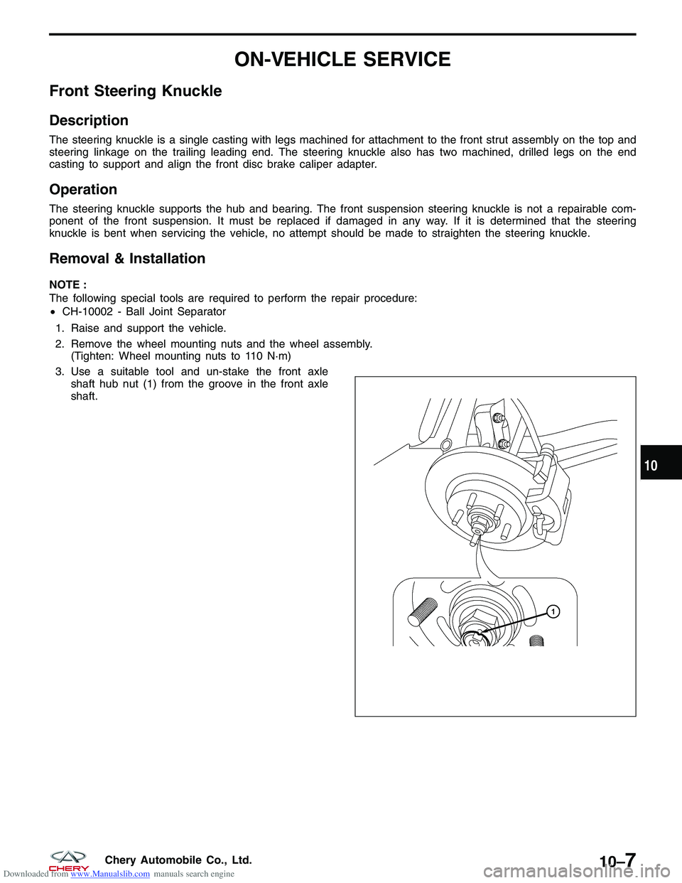
3. Use a suitable tool and un-stake the front axle shaft hub nut (1) from the groove in the front axle
shaft.
??????
10
10–7Chery Automobile Co., Ltd.
Page 1309 of 1903
Downloaded from www.Manualslib.com manuals search engine 4. While a helper applies the brakes to keep the hubfrom rotating, remove the front axle shaft nut (1).
(Tighten: Front axle shaft nut to 135 N·m)
5. Access and remove the front brake rotor (See Front Brake Rotor Remove & Installation in Section 12 Brakes).
6. Remove the wheel speed sensor mounting bolt (1). (Tighten: Wheel speed sensor mounting bolt to 10
± 1 N·m)
7. Remove the wheel speed sensor and set it aside.
8. Remove the lower ball joint mounting nut (1) attaching the lower control arm to the knuckle.
(Tighten: Control arm to steering knuckle nut to
120 ± 10 N·m)
9. Remove the nut (1) attaching the outer tie rod end to the steering knuckle.
(Tighten: Outer tie rod end nut to 32 - 38 N·m)
ON-VEHICLE SERVICE
LTSM090006
LTSM100045
LTSM100006
LTSM110034
10–8Chery Automobile Co., Ltd.
Page 1310 of 1903
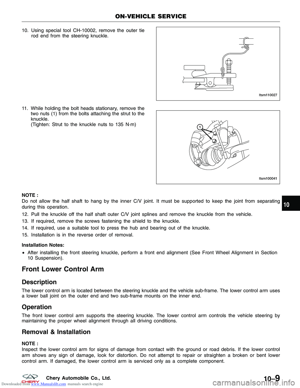
Downloaded from www.Manualslib.com manuals search engine 10. Using special tool CH-10002, remove the outer tierod end from the steering knuckle.
11. While holding the bolt heads stationary, remove the two nuts (1) from the bolts attaching the strut to the
knuckle.
(Tighten: Strut to the knuckle nuts to 135 N·m)
NOTE :
Do not allow the half shaft to hang by the inner C/V joint. It must be supported to keep the joint from separating
during this operation.
12. Pull the knuckle off the half shaft outer C/V joint splines and remove the knuckle from the vehicle.
13. If required, remove the screws fastening the shield to the knuckle.
14. If required, use a suitable tool to press the hub and bearing out of the knuckle.
15. Installation is in the reverse order of removal.
Installation Notes:
• After installing the front steering knuckle, perform a front end alignment (See Front Wheel Alignment in Section
10 Suspension).
Front Lower Control Arm
Description
The lower control arm is located between the steering knuckle and the vehicle sub-frame. The lower control arm uses
a lower ball joint on the outer end and two sub-frame mounts on the inner end.
Operation
The front lower control arm supports the steering knuckle. The lower control arm controls the vehicle steering by
maintaining the proper wheel alignment through all driving conditions.
Removal & Installation
NOTE :
Inspect the lower control arm for signs of damage from contact with the ground or road debris. If the lower control
arm shows any sign of damage, look for distortion. Do not attempt to repair or straighten a broken or bent lower
control arm. If damaged, the lower control arm is serviced only as a complete component.
ON-VEHICLE SERVICE
LTSM110027
LTSM100041
10
10–9Chery Automobile Co., Ltd.
Page 1311 of 1903
Downloaded from www.Manualslib.com manuals search engine 1. Raise and support the vehicle.
2. Remove the wheel mounting nuts and the wheel assembly.(Tighten: Wheel mounting nuts to 110 N·m)
3. Remove the bolt (1) between the control arm and the sub-frame.
(Tighten: Control arm to sub-frame bolt to
180 ± 10 N·m)
4. Remove the nut (1) between the control arm and the steering knuckle.
(Tighten: Control arm to steering knuckle nut to
120 ± 10 N·m)
5. Remove the bolt (1) between the rear rubber sleeve of the control arm and the sub-frame.
(Tighten: Rear rubber sleeve control arm to sub-
frame bolt to 180 ± 10 N·m)
6. Remove the control arm from the vehicle.
7. Perform the following inspection procedure before installation.
ON-VEHICLE SERVICE
LTSM100055
LTSM100006
LTSM100057
10–10Chery Automobile Co., Ltd.
Page 1312 of 1903
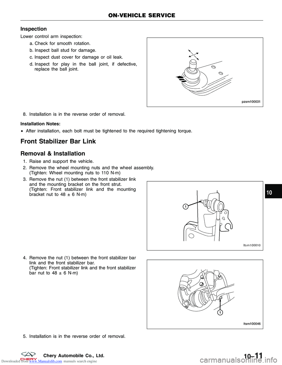
Downloaded from www.Manualslib.com manuals search engine Inspection
Lower control arm inspection:a. Check for smooth rotation.
b. Inspect ball stud for damage.
c. Inspect dust cover for damage or oil leak.
d. Inspect for play in the ball joint, if defective,
replace the ball joint.
8. Installation is in the reverse order of removal.
Installation Notes:
• After installation, each bolt must be tightened to the required tightening torque.
Front Stabilizer Bar Link
Removal & Installation
1. Raise and support the vehicle.
2. Remove the wheel mounting nuts and the wheel assembly.
(Tighten: Wheel mounting nuts to 110 N·m)
3. Remove the nut (1) between the front stabilizer link and the mounting bracket on the front strut.
(Tighten: Front stabilizer link and the mounting
bracket nut to 48 ± 6 N·m)
4. Remove the nut (1) between the front stabilizer bar link and the front stabilizer bar.
(Tighten: Front stabilizer link and the front stabilizer
bar nut to 48 ± 6 N·m)
5. Installation is in the reverse order of removal.
ON-VEHICLE SERVICE
PZSM100031
LTSM100010
LTSM100046
10
10–11Chery Automobile Co., Ltd.