Page 1345 of 1903

Downloaded from www.Manualslib.com manuals search engine ON-VEHICLE SERVICE
Front Wheel Alignment
Front Wheel Alignment Specifications
NOTE :
If the vehicle has been in an accident causing the front axle components to be damaged, the damaged components
must be replaced before performing a front wheel alignment.
FRONT WHEEL ALIGNMENT
FRONT WHEEL ALIGNMENT PREFERRED SETTINGACCEPTABLE RANGE
Camber -51’+9’ to -1°51’
Caster +2°50’+3°30’ to +2°5’
Inclination +11°30’+12°15’ to +10°45’
Toe-Individual 0’+5’ to -5’
Front Axle Toe-In Adjustment
CAUTION:
Do not twist the inner tie rod steering gear boot (bellows) while turning the inner tie rod during
front toe-in adjustment. It may be necessary to remove the clamp where the boot meets the inner
tie rod.
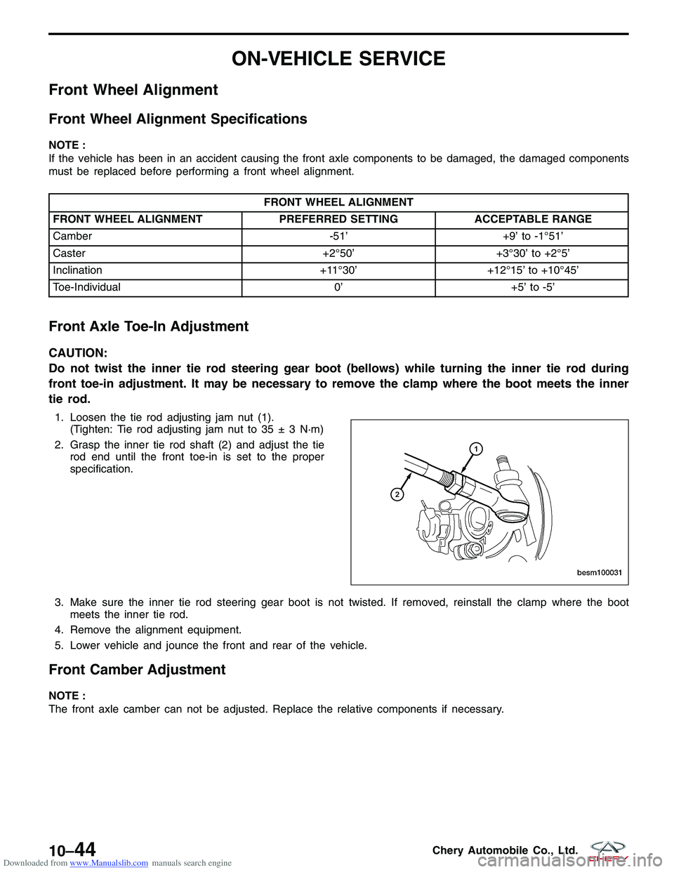
1. Loosen the tie rod adjusting jam nut (1).
(Tighten: Tie rod adjusting jam nut to 35 ± 3 N·m)
2. Grasp the inner tie rod shaft (2) and adjust the tie rod end until the front toe-in is set to the proper
specification.
3. Make sure the inner tie rod steering gear boot is not twisted. If removed, reinstall the clamp where the boot meets the inner tie rod.
4. Remove the alignment equipment.
5. Lower vehicle and jounce the front and rear of the vehicle.
Front Camber Adjustment
NOTE :
The front axle camber can not be adjusted. Replace the relative components if necessary.
BESM100031
10–44Chery Automobile Co., Ltd.
Page 1346 of 1903
Downloaded from www.Manualslib.com manuals search engine Rear Wheel Alignment
Rear Wheel Alignment Specifications
NOTE :
If the vehicle has been in an accident causing the rear axle components to be damaged, the damaged components
must be replaced before performing a rear wheel alignment.
REAR WHEEL ALIGNMENT
REAR WHEEL ALIGNMENT PREFERRED SETTINGACCEPTABLE RANGE
Camber -54’-24’ to -1°24’
Toe-Individual -5’+5’ to -15’
Rear Axle Toe-In Adjustment
1. While holding the cam bolt stationary, loosen the
lower control arm mounting cam nut (1).
(Tighten: Lower control arm mounting cam nut to
80 - 100 N·m)
2. Rotate the cam bolt head left or right until the rear wheel Toe-in for that rear wheel is set to the pre-
ferred specification.
3. While holding the cam bolt head stationary, tighten the Toe-in link mounting cam bolt to the specified
torque.
ON-VEHICLE SERVICE
BESM100031
10
10–45Chery Automobile Co., Ltd.
Page 1347 of 1903
Downloaded from www.Manualslib.com manuals search engine Rear Camber Adjustment
1. While holding the cam bolt stationary, loosen theupper control arm bolt (1).
(Tighten: Upper control arm bolt to 80 - 100 N·m)
2. Rotate the cam bolt head left or right until the rear wheel camber for that rear wheel is set to the pre-
ferred specification.
3. While holding the cam bolt head stationary, tighten the upper control arm bolt to the specified torque.
ON-VEHICLE SERVICE
BESM100031
10–46Chery Automobile Co., Ltd.
Page 1348 of 1903
Downloaded from www.Manualslib.com manuals search engine WHEELS AND TIRES
GENERAL INFORMATION10-48
Description 10-48
Operation 10-48
Specifications 10-48
DIAGNOSIS & TESTING10-50
Vehicle Inspection 10-50
Tire and Wheel Vibration 10-50
Tire Wear Patterns 10-50
Wheel Out-Of-Round Inspection 10-50
ON-VEHICLE SERVICE10-51
Tire Repair 10-51
Description 10-51 Replacement Procedure 10-51
Repair Procedure 10-51
Wheel Assembly 10-52
Description 10-52
Removal & Installation 10-52
Wheel Balance 10-52
Description 10-52
Wheel Balance Procedure 10-53
Tire Rotation 10-53
Description 10-53
Non-Directional Tires 10-54
Directional Tires 10-54
10
10–47Chery Automobile Co., Ltd.
Page 1349 of 1903

Downloaded from www.Manualslib.com manuals search engine GENERAL INFORMATION
Description
Tires are designed and engineered for each specific vehicle. They provide the best overall performance for normal
operation. The ride and handling characteristics match the vehicle’s requirements. With proper care they will give
excellent reliability, traction, skid resistance, and tread life.
Tire Identification
•Tire type, size, load index and speed rating are encoded in the letters and numbers imprinted on the side wall
of the tire.
Spare Tire
• A full size spare tire and wheel assembly is standard equipment on this vehicle. The original tire should be
repaired or replaced at the first opportunity, then reinstalled.
Operation
Driving habits have more effect on tire life than any other factor. Careful drivers will obtain, in most cases, much
greater mileage than severe use or careless drivers. A few of the driving habits which will shorten the life of any tire
are:
•Rapid acceleration
• Severe application of brakes
• High-speed driving
• Taking turns at excessive speeds
• Striking curbs and other obstacles
• Operating vehicle with over or under inflated tire pressures
Specifications
Torque Specifications
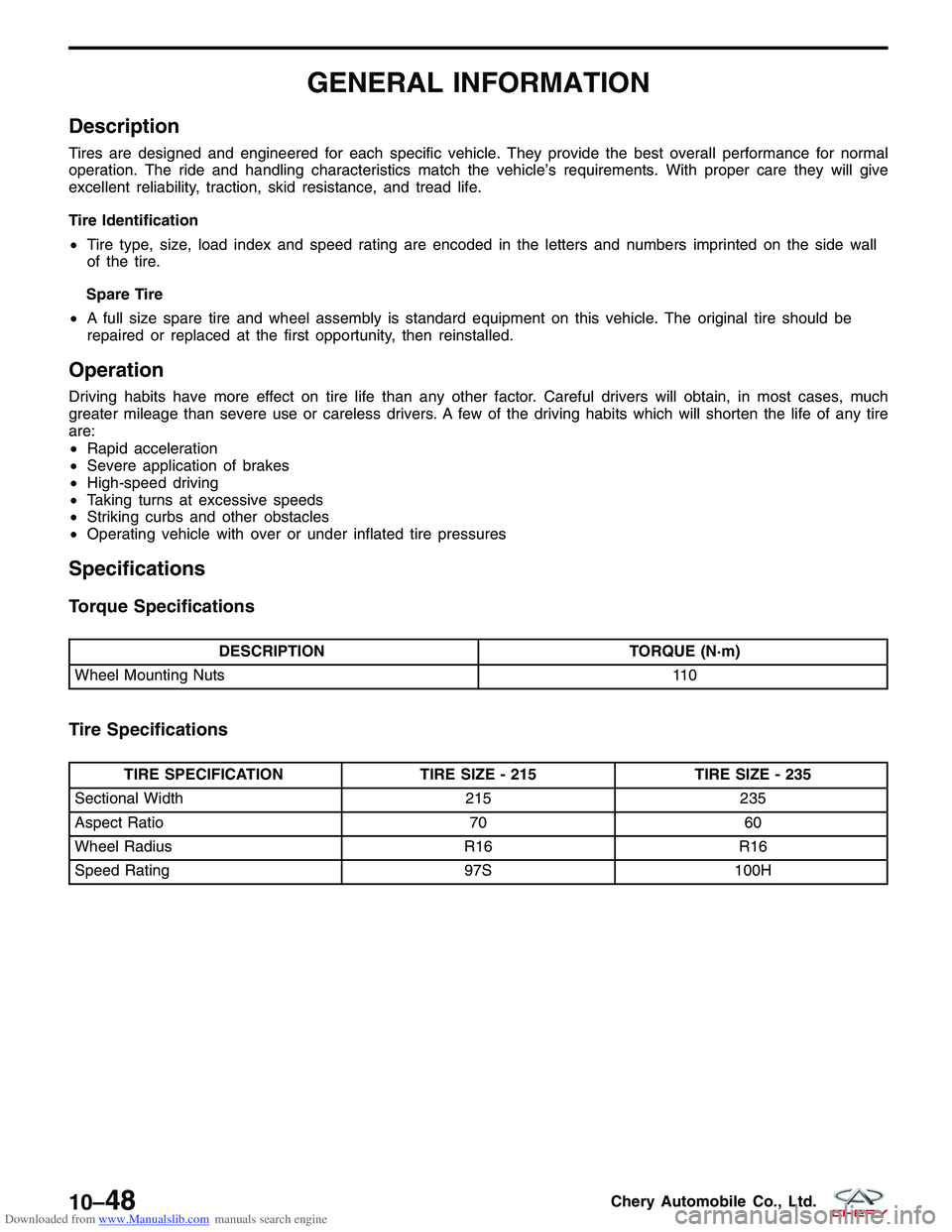
DESCRIPTION TORQUE (N·m)
Wheel Mounting Nuts 110
Tire Specifications
TIRE SPECIFICATIONTIRE SIZE - 215TIRE SIZE - 235
Sectional Width 215235
Aspect Ratio 7060
Wheel Radius R16R16
Speed Rating 97S100H
10–48Chery Automobile Co., Ltd.
Page 1350 of 1903
Downloaded from www.Manualslib.com manuals search engine Tire Pressure Specifications of Cold Tire (kPa)
TIRE (235/60 R16)PRESSURE
Front Tires 200
Rear Tires 200
Spare Tire 250
Rim Out-Of-Round Specifications
DESCRIPTIONMAXIMUM RUN-OUT (mm)
Aluminum Rim 3
GENERAL INFORMATION
10–49Chery Automobile Co., Ltd.
Page 1351 of 1903

Downloaded from www.Manualslib.com manuals search engine DIAGNOSIS & TESTING
Vehicle Inspection
Visual inspection of the vehicle is recommended prior to road testing or performing any other procedure. Raise the
vehicle on a suitable hoist.
Inspect the following:
•Inspect tires and wheels for damage, mud packing and unusual wear; correct as necessary.
• Check and adjust tire pressure to the pressure listed on the label attached to the driver’s door opening.
Tire and Wheel Vibration
Tire and wheel imbalance, runout and force variation can cause vehicles to exhibit steering wheel vibration.
NOTE :
Balance equipment must be calibrated and maintained per equipment manufacturer’s specifications.
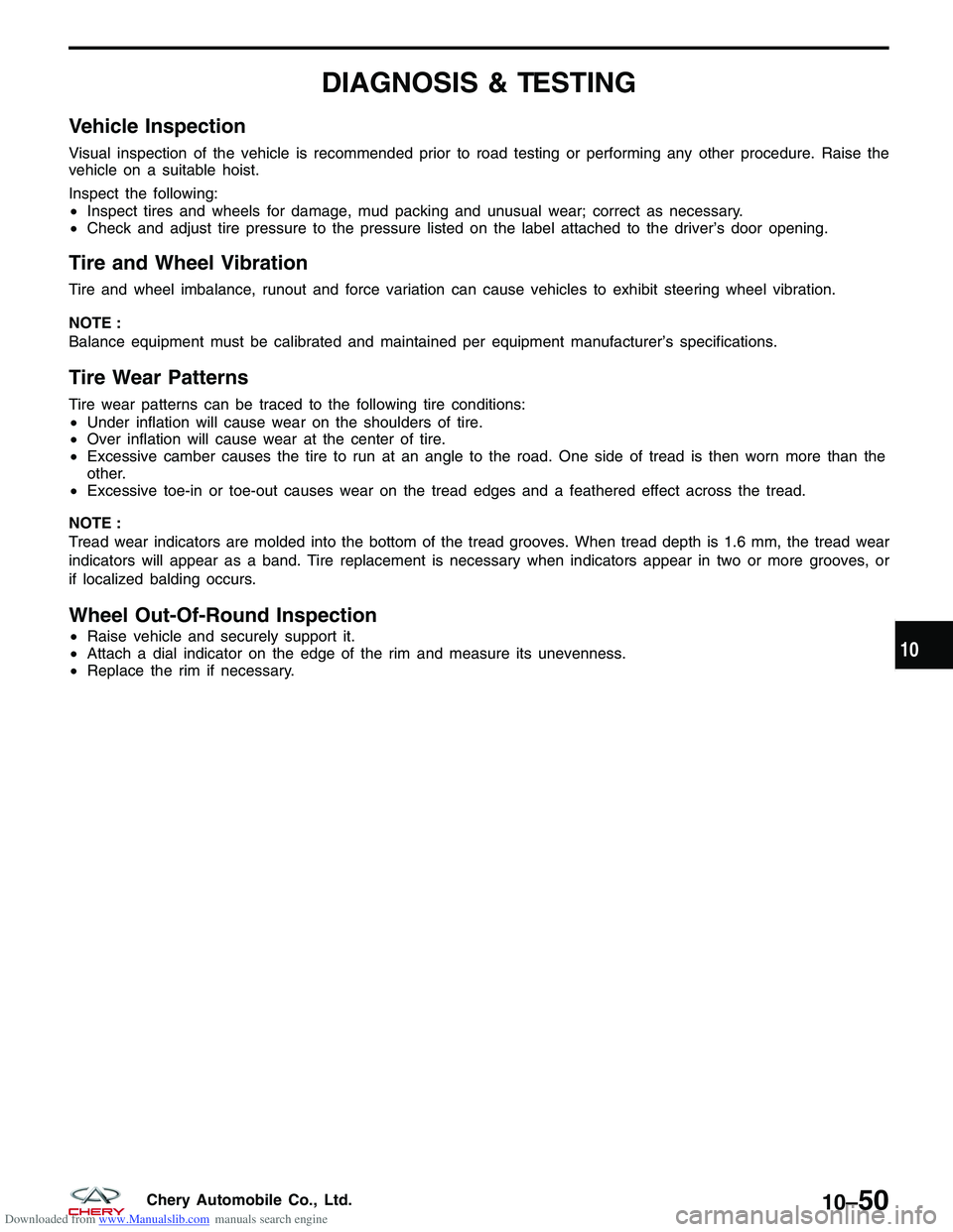
Tire Wear Patterns
Tire wear patterns can be traced to the following tire conditions:
•Under inflation will cause wear on the shoulders of tire.
• Over inflation will cause wear at the center of tire.
• Excessive camber causes the tire to run at an angle to the road. One side of tread is then worn more than the
other.
• Excessive toe-in or toe-out causes wear on the tread edges and a feathered effect across the tread.
NOTE :
Tread wear indicators are molded into the bottom of the tread grooves. When tread depth is 1.6 mm, the tread wear
indicators will appear as a band. Tire replacement is necessary when indicators appear in two or more grooves, or
if localized balding occurs.
Wheel Out-Of-Round Inspection
• Raise vehicle and securely support it.
• Attach a dial indicator on the edge of the rim and measure its unevenness.
• Replace the rim if necessary.10
10–50Chery Automobile Co., Ltd.
Page 1352 of 1903

Downloaded from www.Manualslib.com manuals search engine ON-VEHICLE SERVICE
Tire Repair
Description
Tires are designed and engineered for each specific vehicle. They provide the best overall performance for normal
operation. The ride and handling characteristics match the vehicle’s requirements. With proper care they will give
excellent reliability, traction, skid resistance, and tread life.
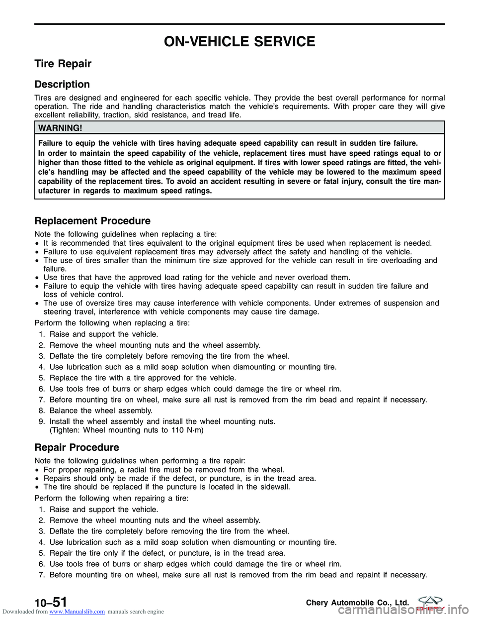
WARNING!
Failure to equip the vehicle with tires having adequate speed capability can result in sudden tire failure.
In order to maintain the speed capability of the vehicle, replacement tires must have speed ratings equal to or
higher than those fitted to the vehicle as original equipment. If tires with lower speed ratings are fitted, the vehi-
cle’s handling may be affected and the speed capability of the vehicle may be lowered to the maximum speed
capability of the replacement tires. To avoid an accident resulting in severe or fatal injury, consult the tire man-
ufacturer in regards to maximum speed ratings.
Replacement Procedure
Note the following guidelines when replacing a tire:
•It is recommended that tires equivalent to the original equipment tires be used when replacement is needed.
• Failure to use equivalent replacement tires may adversely affect the safety and handling of the vehicle.
• The use of tires smaller than the minimum tire size approved for the vehicle can result in tire overloading and
failure.
• Use tires that have the approved load rating for the vehicle and never overload them.
• Failure to equip the vehicle with tires having adequate speed capability can result in sudden tire failure and
loss of vehicle control.
• The use of oversize tires may cause interference with vehicle components. Under extremes of suspension and
steering travel, interference with vehicle components may cause tire damage.
Perform the following when replacing a tire: 1. Raise and support the vehicle.
2. Remove the wheel mounting nuts and the wheel assembly.
3. Deflate the tire completely before removing the tire from the wheel.
4. Use lubrication such as a mild soap solution when dismounting or mounting tire.
5. Replace the tire with a tire approved for the vehicle.
6. Use tools free of burrs or sharp edges which could damage the tire or wheel rim.
7. Before mounting tire on wheel, make sure all rust is removed from the rim bead and repaint if necessary.
8. Balance the wheel assembly.
9. Install the wheel assembly and install the wheel mounting nuts. (Tighten: Wheel mounting nuts to 110 N·m)
Repair Procedure
Note the following guidelines when performing a tire repair:
•For proper repairing, a radial tire must be removed from the wheel.
• Repairs should only be made if the defect, or puncture, is in the tread area.
• The tire should be replaced if the puncture is located in the sidewall.
Perform the following when repairing a tire: 1. Raise and support the vehicle.
2. Remove the wheel mounting nuts and the wheel assembly.
3. Deflate the tire completely before removing the tire from the wheel.
4. Use lubrication such as a mild soap solution when dismounting or mounting tire.
5. Repair the tire only if the defect, or puncture, is in the tread area.
6. Use tools free of burrs or sharp edges which could damage the tire or wheel rim.
7. Before mounting tire on wheel, make sure all rust is removed from the rim bead and repaint if necessary.
10–51Chery Automobile Co., Ltd.