2009 AUDI S6 engine
[x] Cancel search: enginePage 324 of 398

-Tires and wheels
PW-------------------
If you wish to improve comfo rt when operating the vehicle at
normal load (up to 3 occupants) , you can adjust tire pressures to
those spec ified for normal vehi cle load . Before operating the vehi cle
at maximum load, you must in crease the tire pressures to those
specified for ma ximum vehi cle load =>
&.
Bear in mind that the tire pressure monitoring system can on ly
m onito r the t ire pressures you have stored. The syste m does not
recognize the load condition of your vehic le .
The effect iveness of the tir e pr essure moni toring syste m will be
impaired if you store normal load pressures but then operate the
veh ic le a t its ma ximum load=>& . See the
illustrat ion=>
page 321, fig. 247 for the location of the label
on driver's sid e 8-pi llar (c olor of the actual label and exac t loca tion
on the veh ic le wi ll vary slight ly) .
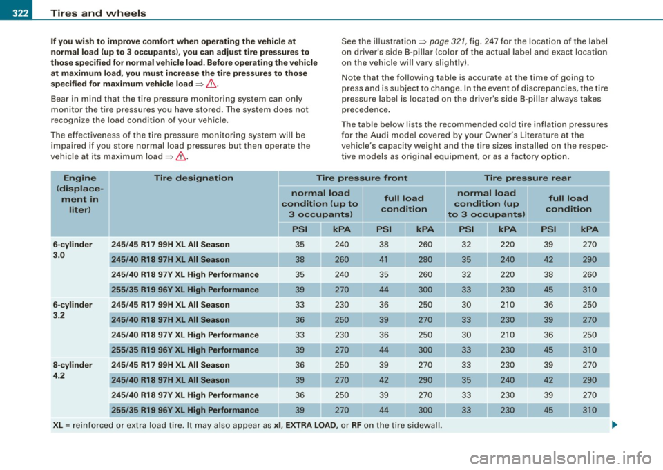
N ote that the fol lowing tab le is accurate at the time of going to
press and is subject to cha nge . In the eve nt of d iscrepa nc ies, t he tire
pressure label is located on the driver's side 8 -pi llar always takes
p recedence .
T he tab le below lists the recommended cold tire inflation pressures
fo r th e A udi m odel co ve red by you r Owner 's Litera ture at the
vehic le's capacity weight and the tire sizes installed on the respec
t ive mode ls as o rigi nal equipment, o r as a fac to ry o ption.
Engine Tire designation Tire pressure front Tire pressure rear
(displace- normal load normal load
ment in condition (up to full load
condition (up full load
liter ) condition
condition
3 occupants) to 3 occupants)
PSI kPA
PSI kPA
PSI kPA PSI
kPA
6-cylinder
245/45 R17 99H XL All Season 35 240 38 260 32 220 39 270
3 .0
245/40 R18 97H XL All Season 38 41 280 35 240 290
245 /40 R18 97V XL High Performance
35 240
35 260 32 220 38 2 60
255 /35 R19 96V XL High Performance 39 270 44 300 33 230 45 3 10
6 -cylinder 245 /45 R17 99H XL All Season 33 230 36 250 3 0 210 36 250
3 .2
245/40 R18 97H XL All Season
36 250 39 270 33 230 39 270
245 /40 R18 97V XL High Performance 33 230 36 250 3 0 21 0 36 250
255 /35 R19 96V XL High Performance 39 270 44 300 33 230 45 310
8 -cylinder 245 /45 R17 99H XL All Season
36 250 39 270
33 230 39 270
4 .2
245/40 R18 97H XL All Season 39 270 42 290 35 2 40 42 2 90
245 /40 R18 97V XL High Performance 36 250 39 270 33 230 39 270
255 /35 R19 96V XL High Performan ce
39 270
44 300 33 230 45 310
XL= reinforce d or ex tra load tire . It may als o ap pear as xi, EXTRA LOAD, or RF o n the tire s ide wall.
Page 345 of 398

What do I do now? 111111 _______________________________ ....:..:..:..:..:.:..:--=.:..::....:.....:.:...::..___;__ _ __,J
& WARNING !continued)
• Never start or run the engine while the vehicle is supported by
the jack.
• If you must work under the vehicle, always use safety stands
specifically designed for this purpose.
• Never use the hexagonal socket in the handle of the screw
driver to loosen or tighten the wheel bolts.
• Always make sure the spare tire and even a flat tire are secured
in place and not loose, otherwise they could fly forward, causing
personal injury to passengers in the vehicle in an accident or
sudden maneuver. •
Tools
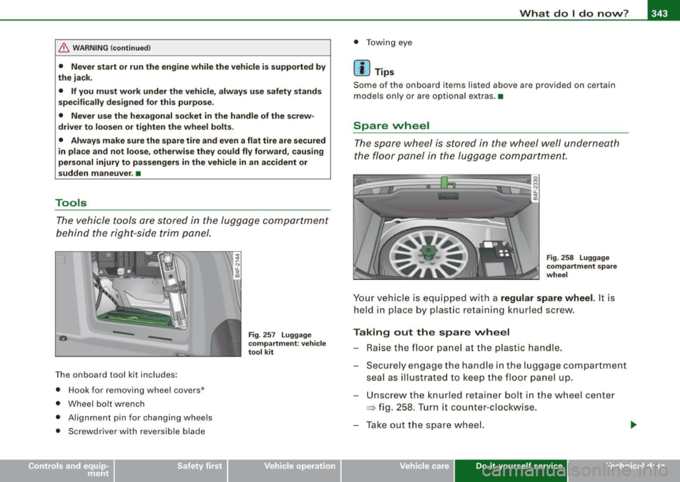
The vehicle tools are stored in the luggage compartment
behind the right-side trim panel.
-
-
The onboard tool kit includes:
• Hook for removing wheel covers *
• Wheel bolt wrench
• Alignment pin for changing wheels
• Screwdriver with reversible blade
Fig. 257 Luggage
compartment: vehicle
tool kit
• Towing eye
[ i] Tips
Some of the on board items listed above are provided on certain
models only or are optional extras.•
Spare wheel
The spare wheel is stored in the wheel well underneath
the floor panel in the luggage compartment.
Fig. 258 Luggage
compartment spare
wheel
Your vehicle is equipped with a regular spare wheel. It is
held in place by plastic retaining knurled screw.
Taking out the spare wheel
- Raise the floor panel at the plastic handle.
- Securely engage the handle in the luggage compartment
seal as illustrated to keep the floor panel up.
Unscrew the knurled retainer bolt in the wheel center
=> fig. 258. Turn it counter-clockwise.
- Take out the spare wheel.
Vehicle care Do-it-yourself service irechnical data
Page 346 of 398

1111!1.___W_ h_ a_ t_ d_o_ l_ d_ o _ n_ o_w _ ? ____________________________________________ _
- Disengage and lower the floor panel before you close the
luggage compartment lid again.
Storing the replaced wheel
- Place the replaced wheel inside the spare wheel well in
the luggage compartment .
Tighten the knurled retaining screw clockwise to secure the wheel in place.
- Disengage and lower the floor panel before you close the
luggage compartment lid again.
& WARNING
Loose items in the passenger compartment can cause serious
personal injury during hard braking or in an accident .
• Never store the spare wheel or jack and tools in the passenger
compartment.
• Always store all jacking equipment, tools, and the spare wheel
in the luggage compartment.
• Tighten the knurled retaining screw for the spare wheel
securely.
[ i] Tips
Check the inflation pressure of the spare tire periodically to keep the
tire ready for use. •
Changing a wheel
Before changing a wheel
Observe the following precautions for your own and your
passenger's safety when changing a wheel.
- After you experience a tire failure, pull the car well away
from moving traffic and try to reach level ground before
you stop :::;. & .
- All passengers should leave the car and move to a safe
location (for instance, behind the guardrail) :::;,& .
- Engage the parking brake to prevent your vehicle from
rol ling unintentionally :::;.& .
- Move selector lever to position P :::;. & .
-If you are towing a trailer: unhitch the trailer from your
vehicle.
- Take the jack and the spare tire out of the luggage
compartment:::;.
page 342.
& WARNING
You or your passengers could be injured while changing a wheel if
you do not follow these safety precautions:
• If you have a flat tire, move a safe distance off the road. Turn off
the engine, turn the emergency flashers on and use other warning
devices to alert other motorists.
• Make sure that passengers wait
in a safe place away from the
vehicle and well away from the road and traffic.
• To help prevent the vehicle from moving suddenly and possibly
slipping off the jack, always fully set the parking brake and block
the wheel diagonally opposite the wheel being changed. When one ...
Page 354 of 398

-Fuses and bulbs Pffl..._ _____________________ _
[ i J Tip s
You are wel l advised to keep a supply of spare fuses in your vehicle .
Fuses with the proper ampere ratings are availab le at your Audi
dea ler. •
Fuse Location , Instrument Panel left
Fig . 267 Fuse pa nel
l ayo ut
Some of the equipment items listed are optional or only ava ilable on
certain model configurations .
Note th at t he fo llo wi ng t able i s acc urat e at th e time of goin g to
pr ess and is subject t o ch ang e. In th e eve nt of d iscrep ancie s, th e
labe l on th e in side of th e cover always ta kes prece de nce .
The power seats are protected by cir cuit br eaker s, which automati
cally reset after a few seconds after the overload has been reme
died.
N o. Equipm ent
1 Not used
2
3
4
Not used
Engine management
Oil level sensor Amps
5
5
No
.
5
6
..
7
8
9
10
1 1
12
13
14
15
16
17
18
19
20
21
22
23
24
25
26
27
28
Equipm ent
Climate cont rol , tire pressure monitoring sys
tem
Electronic Stabilization Program (ESP), clutch
sensor
Diagnostic connector
Homelink control unit
Automa tic dimming interior mirror
Adaptive Cruise Control
Not used
Diagnostic connector
Switch modu le steering column
Not used
I nstrument c luster, control module Ga teway
Telephone, cell phone E lectronic Stabilization Program (ESP)
Headlight electronics, left -side
Rain sensor
Heated washer nozzles
Seat adjustment (driver)
MMI display
E lectromechanica l parking brake
Not used
Not used
Not used
N ot used
Not used Amps
5
5
5
5
5
5
10
10
10
5
10
5
5
5
10
5
5
-
Page 355 of 398

Fuses and bul bs -_____________ -----=----.;....:..::.:....:.::;______J
No. Equipm ent
29 Not used
30 Not used
31 Back-up light switch, transmission, engine
components
Intelligent power mo dule driver (footwell l ight
32 and front headlights, horn, wiper system, elec
trically adjusta ble steering wheel)
33 Intelligent power modu le driver
(lights left-side)
---,--
34
35
36
37
38
39
I nte lligent power module driver
(lights right-side)
Not used
Headlight washer system
E lectronic Stabilization Program (ESP)
Wip er system
Door control module left -side
Horn
41 Heater fan
42 Control module electronic ignition lock/electri
cally adjustable steering wheel
43 Rear windsh iel d wiper (Avant)
44 Power window opener (left-side) Amps
15
30
25
25
30 25
30
15
25
40
30
15
35
-
•
Fuse Location , Instrument Panel right
Fig. 2 68 F use pan el
la yo ut
Some of the equipment items listed are optional or on ly available on
certain model configu rations.
Note that the following table is ac curate at the time of g oing to
press and is subject t o change . In the eve nt of d iscrepan cies , th e
l a b el on t he in side of the cover alw ay s take s prec eden ce.
The power seats are protected by cir cuit breaker s, which automati
ca lly reset after a few seconds a fter the ove rload has been reme
died.
No . Equipment Amps
Fu se holder (bla ck )
1 Control module Convenience key 15
2
Cigarette lighter front 20
3
Tire pressure moni tor ing system 5
4 E lectrica l outlet front (center conso le) 20
5
Intelligent power module passenger 15 (glove box lock)
6 Door control module right -side 15
Sunroof 20
Vehicle care Do-it-yourself service irechnical data
Page 357 of 398

Fuses and bulbs -
----------------
•
No. Equipment
Fuse holder (brown)
1 R ear vi ew
2 Elect ric rea r lid (Ava nt)
3 Elect ric rea r lid (Avant)
4 Ele ctr ic rea r lid (Ava nt)
5 Communication, Antenna amplifier
6 N ot used
7 M MI
8 Not used
9 Digital Tuner
10 Not u sed
11 Not used
1 2 Not u sed
Bulbs
Replacing light bulbs
Amps
5
30
30
20
5
5
5
5
Fo r yo ur sa fe ty, we rec om mend t hat yo u have your a utho
rize d Audi d ea le r r ep la ce b urned out bul bs fo r you.
It is becoming increasing ly more and more difficult to replace
ve hicle light bu lbs s ince i n many cases, ot her parts of the car mus t
f irst be removed before you are able to get to the bu lb . T his applies
es pecia lly to the ligh t bu lb s in th e fro nt of y our ca r which you can
only reach through the engine compartment .
Sheet meta l and b ulb ho lders can have s harp edge s that can cause
ser ious c uts, and parts must be cor rectl y taken apart a nd t hen p ro p
erly put back together to he lp prevent breakage of parts and long
•
term damage from water that can enter housings that have not
b ee n properly resea led .
For your safety , we recommend that you have your authorized Audi
dea ler replace any bu lbs for you, since your dealer has the proper
t ools, the cor rect bulbs and the expertise.
Gas di scharge lamps (Xenon lights )*:
Due to the high e lectrica l voltage, have the bulbs replaced by a qual
ified technician . H eadlights with Xenon light can be identified by the
high voltage sticker .
& WARNING
Contact with high-voltage components of the ele ctrical system
and imprope r repla cement of gas discharge (Xenon) headlight
bulbs can cause serious personal injury and death.
• Xenon bulbs are pressurized and can explode when being
changed.
• Chang ing Xenon lamps requires the special training , instruc
tions and equipment .
• Only an authorized Audi dealer or other qualified workshop
s hould change the bulbs in ga s di scharge lamps.
& WARNING
The re are parts with sharp edges on the openings and on the bulb
holders that can cause serious cuts.
• If you are uncertain about what to do , have the work performed
by an authorized Audi dealer or other qualified workshop. Serious
per sonal injury may result from improperly performed work .
[ i ] Tips
• I f you must replace the light bu lbs yourself, a lways remember
that the engine compartment of any vehicle is a hazardous area to .,,
Do-it-yourself service
Page 358 of 398

11111.___F_ u_ s _ e_s _ a_n _ d_ b_ u_lb _ s _______________________________________________ _
work in. Always read and heed al l WARNI NGS=> page 293, "Engine
c ompartment" =>& .
• It is best to ask your authorized Audi dealer whenever you need
to change a bulb. •
Page 359 of 398

________________________________________________ E _m_ e_r.:g :;,. e_ n_c ...: y:.- s_ i_ t _u _a_ t_ i_ o _ n_ s __ lll
•
Emergency situations
General
This chapter is intended for trained emergency crews and working
pe rsonnel who have the necessary tools and equ ipment to perform
these operations. •
Starting by pushing or towing
(D Note
You r ve hicle is eq uipped w ith an automatic trans missi on. C o nse
quent ly, the engine cannot be started by pushing or towing .•
Starting with jumper cables
If necess ary, the en gine can b e sta rted by conn ectin g it to
the battery of anothe r vehicle.
If th e engine should fail to start because of a discharged or weak
b at te ry, the batt ery ca n be co nnected t o the ba ttery of
another
vehicle, using a pair of jumper cables to start the engine .
Jumper cables
Use
only jumper cables of sufficiently large cross section to carry the
s tarte r curre nt safely. Refer t o the manu fac tu rer 's specif ica tions.
Use only ju mper cabl es with
insulated terminal clamps whic h are
distinct ly marked:
plus (+l cable in mo st cas es c olored red
minus
(- 1 cable in most cases colored black.
& WARNING
Batteries contain electricity, acid , and gas. Any of the se can cause
very ser ious or fatal injury . Follow the instructions below for safe
handling of your vehicle 's battery .
• Always shield your eyes and avoid leaning over the battery
whenever possible .
• A discharged battery can freeze at temperatures just below
32 °F (0 °C l. Before connecting a jumper cable , you must thaw the
frozen battery completely , otherwise it could explode .
• Do not allow battery acid to conta ct eyes or skin. Flush any
contacted area with water immediately.
• Improper use of a booster battery to start a vehicle may cause
an explosion.
• Vehicle batteries generate explosive gases . Keep sparks , flame
and lighted c igarettes away from batteries.
• Do not try to jump start any vehicle with a low acid level in the
battery.
• The voltage of the booster battery must also have a 12-Volt
rating. The capacity (Ah l of the booster battery should not be
lower than that of the discharged battery . Use of batteries of
different voltage or substantially different "Ah" rating may cause
an explosion and personal injury .
• Never charge a frozen battery. Gas trapped in the ice may cause
an explosion.
• Never charge or use a battery that has been frozen . The battery
c ase may have be weakened .
• Use of batter ies of different voltage or substantially different
c apacity (Ah l rating may cause an explosion and injury . The
capacity (Ahl of the booster batte ry should not be lower than that
of the discharged battery. _..
Do-it -yourself service