Page 65 of 108

4. Remove the reservoir cap, add
coolant to the maximum level
ma")
PERIODIC MAINTENANCE AND MINOR REPAIR
6-16
6 3. If the coolant is at or below the
minimum level mark, remove pan-
el B. (See page 6-7.)
4. Remove the reservoir cap, add
coolant to the maximum level
mark, and then install the reservoir
cap.
CAUTION:
ECA10471
�
If coolant is not available, use
distilled water or soft tap water
instead. Do not use hard water
or salt water since it is harmful
to the engine.
�
If water has been used instead
of coolant, replace it with cool-
ant as soon as possible, other-
wise the cooling system will not
be protected against frost and
corrosion.
�
If water has been added to the
coolant, have a Yamaha dealer
check the antifreeze content of
the coolant as soon as possible,
otherwise the effectiveness ofthe coolant will be reduced.WARNING
EWA10380
Never attempt to remove the radiatorcap when the engine is hot.
5. Install the panel.NOTE:�
The radiator fans are automatically
switched on or off according to the
coolant temperature in the radia-
tor.
�
If the engine overheats, see page6-44 for further instructions.
EAU39002
To change the coolant
1. Place the vehicle on a level sur-
face and let the engine cool if nec-
essary.
2. Remove cowlings B and C. (See
page 6-7.)
1. Coolant reservoir
2. Maximum level mark
3. Minimum level mark
1. Coolant reservoir cap
Coolant reservoir capacity (up to the
maximum level mark):
0.25 L (0.26 US qt) (0.22 Imp.qt)
U13SE0E0.book Page 16 Monday, August 27, 2007 4:53 PM
Page 66 of 108

PERIODIC MAINTENANCE AND MINOR REPAIR
6-17
63. Place a container under the engine
to collect the used coolant.
4. Remove the radiator cap.
WARNING
EWA10380
Never attempt to remove the radiatorcap when the engine is hot.
5. Remove the coolant drain bolt to
drain the cooling system.
6. Move the hose clamp in the direc-
tion shown, and then disconnect
the radiator hose to drain the radi-
ator.7. Remove the coolant reservoir by
removing the bolts.
8. Remove the coolant reservoir cap,
and then turn the coolant reservoir
upside down to empty it.9. After the coolant is completely
drained, thoroughly flush the cool-
ing system with clean tap water.
10. Install the coolant reservoir by in-
stalling the bolts.
11. Connect the radiator hose, and
then move the hose clamp back to
its original position.
12. Install the coolant drain bolt, and
then tighten it to the specified
torque.
NOTE:Check the washer for damage and re-place it if necessary.
1. Radiator cap
1. Coolant drain bolt
2. Hose clamp
3. Radiator hose
1. Coolant reservoir cap
2. Coolant reservoir
3. Bolt
U13SE0E0.book Page 17 Monday, August 27, 2007 4:53 PM
Page 67 of 108

PERIODIC MAINTENANCE AND MINOR REPAIR
6-18
6 13. Pour the recommended coolant
into the reservoir to the maximum
level mark, and then install the
coolant reservoir cap.
14. Pour the recommended coolant
into the radiator until it is full.
CAUTION:
ECA10471
�
If coolant is not available, use
distilled water or soft tap water
instead. Do not use hard water
or salt water since it is harmful
to the engine.
�
If water has been used instead
of coolant, replace it with cool-
ant as soon as possible, other-
wise the cooling system will not
be protected against frost and
corrosion.
�
If water has been added to the
coolant, have a Yamaha dealer
check the antifreeze content of
the coolant as soon as possible,
otherwise the effectiveness ofthe coolant will be reduced.
15. Install the radiator cap, start the
engine, let it idle for several min-
utes, and then turn it off.
16. Remove the radiator cap to check
the coolant level in the radiator. If
necessary, add sufficient coolant
until it reaches the top of the radia-
tor, and then install the radiator
cap.17. Start the engine, and then check
the vehicle for coolant leakage. If
coolant is leaking, have a Yamaha
dealer check the cooling system.
18. Install the cowlings.
Tightening torque:
Coolant drain bolt:
10 Nm (1.0 m·kgf, 7.2 ft·lbf)
Antifreeze/water mixture ratio:
1:1
Recommended antifreeze:
High-quality ethylene glycol anti-
freeze containing corrosion inhibitors
for aluminum engines
Coolant quantity:
Radiator capacity (including all
routes):
2.30 L (2.43 US qt) (2.02 Imp.qt)
Coolant reservoir capacity (up to the
maximum level mark):
0.25 L (0.26 US qt) (0.22 Imp.qt)
U13SE0E0.book Page 18 Monday, August 27, 2007 4:53 PM
Page 68 of 108
PERIODIC MAINTENANCE AND MINOR REPAIR
6-19
6
EAU36762
Air filter element The air filter element must be replaced
at the intervals specified in the periodic
maintenance and lubrication chart.
Have a Yamaha dealer replace the air
filter element.
EAU44730
Checking the engine idling
speed The engine idling speed must be
checked as follows and, if necessary,
adjusted by a Yamaha dealer at the in-
tervals specified in the periodic mainte-
nance and lubrication chart.
Start the engine and warm it up for sev-
eral minutes at 1000–2000 r/min while
occasionally revving it to 4000–5000
r/min.
EAU21382
Checking the throttle cable
free play The throttle cable free play should mea-
sure 3.0–5.0 mm (0.12–0.20 in) at the
throttle grip. Periodically check the
throttle cable free play and, if neces-
sary, have a Yamaha dealer adjust it.
Engine idling speed:
1250–1350 r/min
1. Throttle cable free play
U13SE0E0.book Page 19 Monday, August 27, 2007 4:53 PM
Page 69 of 108

PERIODIC MAINTENANCE AND MINOR REPAIR
6-20
6
EAU21401
Valve clearance The valve clearance changes with use,
resulting in improper air-fuel mixture
and/or engine noise. To prevent this
from occurring, the valve clearance
must be adjusted by a Yamaha dealer
at the intervals specified in the periodic
maintenance and lubrication chart.
EAU21771
Tires To maximize the performance, durabil-
ity, and safe operation of your motor-
cycle, note the following points
regarding the specified tires.
Tire air pressure
The tire air pressure should be checked
and, if necessary, adjusted before each
ride.
WARNING
EWA10500
�
The tire air pressure must be
checked and adjusted on cold
tires (i.e., when the temperature
of the tires equals the ambient
temperature).
�
The tire air pressure must be ad-
justed in accordance with the
riding speed and with the total
weight of rider, passenger, car-
go, and accessories approvedfor this model.
WARNING
EWA11020
Because loading has an enormous
impact on the handling, braking,
performance and safety characteris-
tics of your motorcycle, you should
keep the following precautions in
mind.
Tire air pressure (measured on cold
tires):
0–90 kg (0–198 lb):
Fr o nt :
250 kPa (36 psi) (2.50 kgf/cm²)
Rear:
290 kPa (42 psi) (2.90 kgf/cm²)
90–190 kg (198–419 lb):
Fr o nt :
250 kPa (36 psi) (2.50 kgf/cm²)
Rear:
290 kPa (42 psi) (2.90 kgf/cm²)
High-speed riding:
Fr o nt :
250 kPa (36 psi) (2.50 kgf/cm²)
Rear:
290 kPa (42 psi) (2.90 kgf/cm²)
Maximum load*:
190 kg (419 lb)
* Total weight of rider, passenger, car-
go and accessories
U13SE0E0.book Page 20 Monday, August 27, 2007 4:53 PM
Page 70 of 108

PERIODIC MAINTENANCE AND MINOR REPAIR
6-21
6
�
NEVER OVERLOAD THE
MOTORCYCLE! Operation of an
overloaded motorcycle may re-
sult in tire damage, loss of con-
trol, or severe injury. Make sure
that the total weight of rider,
passenger, cargo, and accesso-
ries does not exceed the speci-
fied maximum load for the
vehicle.
�
Do not carry along loosely
packed items, which can shift
during a ride.
�
Securely pack the heaviest
items close to the center of the
motorcycle and distribute the
weight evenly on both sides.
�
Adjust the suspension and tire
air pressure with regard to the
load.
�
Check the tire condition and airpressure before each ride.Tire inspection
The tires must be checked before each
ride. If the center tread depth reaches
the specified limit, if the tire has a nail or
glass fragments in it, or if the sidewall is
cracked, have a Yamaha dealer re-
place the tire immediately.
NOTE:The tire tread depth limits may differ
from country to country. Always complywith the local regulations.
WARNING
EWA10470
�
Have a Yamaha dealer replace
excessively worn tires. Besides
being illegal, operating the vehi-
cle with excessively worn tires
decreases riding stability and
can lead to loss of control.
�
The replacement of all wheel
and brake related parts, includ-
ing the tires, should be left to a
Yamaha dealer, who has the
necessary professional knowl-edge and experience.
Tire information
1. Tire sidewall
2. Tire tread depthMinimum tire tread depth (front and
rear):
1.6 mm (0.06 in)
1. Tire air valve
2. Tire air valve core
3. Tire air valve cap with seal
U13SE0E0.book Page 21 Monday, August 27, 2007 4:53 PM
Page 71 of 108

PERIODIC MAINTENANCE AND MINOR REPAIR
6-22
6 This motorcycle is equipped with cast
wheels and tubeless tires with valves.
WARNING
EWA10480
�
The front and rear tires should
be of the same make and de-
sign, otherwise the handling
characteristics of the motor-
cycle cannot be guaranteed.
�
After extensive tests, only the
tires listed below have been ap-
proved for this model by
Yamaha Motor Co., Ltd.
�
Always make sure that the valve
caps are securely installed to
prevent air pressure leakage.
�
Use only the tire valves and
valve cores listed below to
avoid tire deflation during ahigh-speed ride.
WARNING
EWA10600
This motorcycle is fitted with super-
high-speed tires. Note the following
points in order to make the most ef-
ficient use of these tires.�
Use only the specified replace-
ment tires. Other tires may run
the danger of bursting at super
high speeds.
�
Brand-new tires can have a rela-
tively poor grip on certain road
surfaces until they have been“broken in”. Therefore, it is ad-
visable before doing any high-
speed riding to ride conserva-
tively for approximately 100 km
(60 mi) after installing a new tire.
�
The tires must be warmed up
before a high-speed run.
�
Always adjust the tire air pres-
sure according to the operatingconditions.
Front tire:
Size:
120/70 ZR17M/C (58W)
Manufacturer/model:
BRIDGESTONE/BT016F F
DUNLOP/Qualifier PT M
Rear tire:
Size:
180/55 ZR17M/C (73W)
Manufacturer/model:
BRIDGESTONE/BT016R F
DUNLOP/Qualifier PT M
FRONT and REAR:
Tire air valve:
TR412
Va l ve c o r e :
#9100 (original)
U13SE0E0.book Page 22 Monday, August 27, 2007 4:53 PM
Page 72 of 108

PERIODIC MAINTENANCE AND MINOR REPAIR
6-23
6
EAU21960
Cast wheels To maximize the performance, durabil-
ity, and safe operation of your vehicle,
note the following points regarding the
specified wheels.�
The wheel rims should be checked
for cracks, bends or warpage be-
fore each ride. If any damage is
found, have a Yamaha dealer re-
place the wheel. Do not attempt
even the smallest repair to the
wheel. A deformed or cracked
wheel must be replaced.
�
The wheel should be balanced
whenever either the tire or wheel
has been changed or replaced. An
unbalanced wheel can result in
poor performance, adverse han-
dling characteristics, and a short-
ened tire life.
�
Ride at moderate speeds after
changing a tire since the tire sur-
face must first be “broken in” for it
to develop its optimal characteris-
tics.
EAU33890
Adjusting the clutch lever free
play The clutch lever free play should mea-
sure 10.0–15.0 mm (0.39–0.59 in) as
shown. Periodically check the clutch le-
ver free play and, if necessary, adjust it
as follows.
To increase the clutch lever free play,
turn the adjusting bolt at the clutch lever
in direction (a). To decrease the clutch
lever free play, turn the adjusting bolt in
direction (b).
NOTE:If the specified clutch lever free play
cannot be obtained as describedabove, proceed as follows.
1. Fully turn the adjusting bolt at the
clutch lever in direction (a) to loos-
en the clutch cable.
2. Loosen the locknut at the crank-
case.
3. To increase the clutch lever free
play, turn the adjusting nut in direc-
tion (a). To decrease the clutch le-
ver free play, turn the adjusting nut
in direction (b).
4. Tighten the locknut.
1. Clutch lever free play adjusting bolt
2. Clutch lever free play
1. Locknut
2. Clutch lever free play adjusting nut (crank-
case)
U13SE0E0.book Page 23 Monday, August 27, 2007 4:53 PM
 1
1 2
2 3
3 4
4 5
5 6
6 7
7 8
8 9
9 10
10 11
11 12
12 13
13 14
14 15
15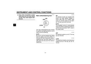 16
16 17
17 18
18 19
19 20
20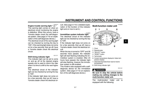 21
21 22
22 23
23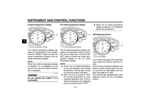 24
24 25
25 26
26 27
27 28
28 29
29 30
30 31
31 32
32 33
33 34
34 35
35 36
36 37
37 38
38 39
39 40
40 41
41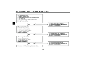 42
42 43
43 44
44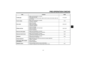 45
45 46
46 47
47 48
48 49
49 50
50 51
51 52
52 53
53 54
54 55
55 56
56 57
57 58
58 59
59 60
60 61
61 62
62 63
63 64
64 65
65 66
66 67
67 68
68 69
69 70
70 71
71 72
72 73
73 74
74 75
75 76
76 77
77 78
78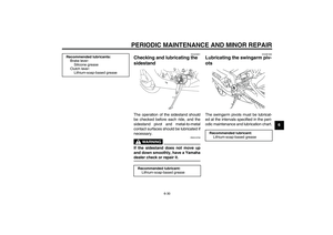 79
79 80
80 81
81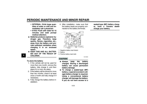 82
82 83
83 84
84 85
85 86
86 87
87 88
88 89
89 90
90 91
91 92
92 93
93 94
94 95
95 96
96 97
97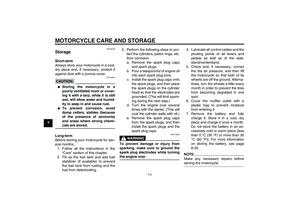 98
98 99
99 100
100 101
101 102
102 103
103 104
104 105
105 106
106 107
107