Page 33 of 108

INSTRUMENT AND CONTROL FUNCTIONS
3-19
3
EAU13442
Catalytic converters This vehicle is equipped with catalytic
converters in the exhaust system.
WARNING
EWA10860
The exhaust system is hot after op-
eration. Make sure that the exhaust
system has cooled down before do-ing any maintenance work.CAUTION:
ECA10700
The following precautions must be
observed to prevent a fire hazard or
other damages.�
Use only unleaded gasoline.
The use of leaded gasoline will
cause unrepairable damage to
the catalytic converter.
�
Never park the vehicle near pos-
sible fire hazards such as grass
or other materials that easily
burn.
�
Do not allow the engine to idletoo long.
EAU39031
Seats Rider seat
To remove the rider seatPull back the rear of the rider seat as
shown, remove the bolts, and then pull
the seat off.
To install the rider seatInsert the projection on the front of the
rider seat into the seat holder as
shown, place the seat in the original po-
sition, and then install the bolts.Passenger seat
To remove the passenger seat
1. Insert the key into the seat lock,
and then turn it clockwise.
1. Bolt
1. Projection
2. Seat holder
1. Passenger seat lock
2. Unlock.
U13SE0E0.book Page 19 Monday, August 27, 2007 4:53 PM
Page 34 of 108

INSTRUMENT AND CONTROL FUNCTIONS
3-20
32. While holding the key in that posi-
tion, lift the front of the passenger
seat and pull it forward.
To install the passenger seat
1. Insert the projections on the pas-
senger seat into the seat holders
as shown, and then push the front
of the seat down to lock it in place.
2. Remove the key.NOTE:Make sure that the seats are properlysecured before riding.
EAU39072
Helmet holding cable A helmet holding cable is provided in
the owner’s tool kit to secure two hel-
mets to the helmet cable holder
equipped on the bottom of the passen-
ger seat.
To secure a helmet with the helmet
holding cable
1. Remove the passenger seat. (See
page 3-19.)
2. Clip the middle snap hook of the
cable onto the cable holder.3. Pass one of the other snap hooks
of the cable through the helmet
strap buckle, and then clip the
snap hook onto the cable holder as
shown.
4. Install the passenger seat.
1. Projection
2. Seat holder
1. Helmet holding cable
2. Helmet cable holder
3. Middle snap hook
1. Helmet holding cable
2. Helmet
1. Helmet holding cable
2. Helmet
U13SE0E0.book Page 20 Monday, August 27, 2007 4:53 PM
Page 35 of 108

INSTRUMENT AND CONTROL FUNCTIONS
3-21
3
WARNING
EWA14330
Never ride with a helmet attached to
a helmet holding cable, since the
helmet may hit objects, causing lossof control and possibly an accident.
To release a helmet from the helmet
holding cable
1. Remove the passenger seat.
2. Unfasten the snap hooks from the
cable holder, and then remove the
cable from the helmet strap buck-
le.
3. Install the passenger seat.
EAU38942
Adjusting the front fork This front fork is equipped with spring
preload adjusting bolts, rebound damp-
ing force adjusting screws, compres-
sion damping force adjusting bolts (for
fast compression damping) and com-
pression damping force adjusting bolts
(for slow compression damping).
WARNING
EWA10180
Always adjust both fork legs equal-
ly, otherwise poor handling and lossof stability may result.
Spring preloadTo increase the spring preload and
thereby harden the suspension, turn
the adjusting bolt on each fork leg in di-
rection (a). To decrease the spring pre-
load and thereby soften the
suspension, turn the adjusting bolt on
each fork leg in direction (b).
NOTE:Align the appropriate groove on the ad-
justing mechanism with the top of thefront fork collar.
1. Spring preload adjusting bolt
1. Current setting
2. Front fork collar
U13SE0E0.book Page 21 Monday, August 27, 2007 4:53 PM
Page 36 of 108
")
INSTRUMENT AND CONTROL FUNCTIONS
3-22
3
Rebound damping force
To increase the rebound damping force
and thereby harden the rebound damp-
ing, turn the adjusting screw on each
fork leg in direction (a). To decrease the
rebound damping force and thereby
soften the rebound damping, turn the
adjusting screw on each fork leg in di-
rection (b).Compression damping force
To adjust the compression damping
force (for fast compression damping)To increase the compression damping
force and thereby harden the compres-
sion damping, turn the adjusting bolt on
each fork leg in direction (a). To de-crease the compression damping force
and thereby soften the compression
damping, turn the adjusting bolt on
each fork leg in direction (b).
To adjust the compression damping
force (for slow compression damping)
Spring preload setting:
Minimum (soft):
0
Standard:
2
Maximum (hard):
51. Rebound damping force adjusting screw
Rebound damping setting:
Minimum (soft):
25 click(s) in direction (b)*
Standard:
20 click(s) in direction (b)*
Maximum (hard):
1 click(s) in direction (b)*
* With the adjusting screw fully turned
in direction (a)1. Compression damping force adjusting bolt
(for fast compression damping)
Compression damping setting (for
fast compression damping):
Minimum (soft):
4 turn(s) in direction (b)*
Standard:
2 turn(s) in direction (b)*
Maximum (hard):
0 turn(s) in direction (b)*
* With the adjusting bolt fully turned in
direction (a)1. Compression damping force adjusting bolt
(for slow compression damping)
U13SE0E0.book Page 22 Monday, August 27, 2007 4:53 PM
Page 37 of 108
. To de-
crease")
INSTRUMENT AND CONTROL FUNCTIONS
3-23
3 To increase the compression damping
force and thereby harden the compres-
sion damping, turn the adjusting bolt on
each fork leg in direction (a). To de-
crease the compression damping force
and thereby soften the compression
damping, turn the adjusting bolt on
each fork leg in direction (b).
CAUTION:
ECA10100
Never attempt to turn an adjusting
mechanism beyond the maximum orminimum settings.NOTE:Although the total number of clicks of a
damping force adjusting mechanism
may not exactly match the above spec-
ifications due to small differences inproduction, the actual number of clicks
always represents the entire adjusting
range. To obtain a precise adjustment,
it would be advisable to check the num-
ber of clicks of each damping force ad-
justing mechanism and to modify the
specifications as necessary.
EAU42940
Adjusting the shock absorber
assembly This shock absorber assembly is
equipped with a spring preload adjust-
ing ring, a rebound damping force ad-
justing screw, a compression damping
force adjusting bolt (for fast compres-
sion damping) and a compression
damping force adjusting bolt (for slow
compression damping).CAUTION:
ECA10100
Never attempt to turn an adjusting
mechanism beyond the maximum orminimum settings.
Compression damping setting (for
slow compression damping):
Minimum (soft):
20 click(s) in direction (b)*
Standard:
15 click(s) in direction (b)*
Maximum (hard):
1 click(s) in direction (b)*
* With the adjusting bolt fully turned in
direction (a)
U13SE0E0.book Page 23 Monday, August 27, 2007 4:53 PM
Page 38 of 108
. To de-
crease the spring preload and t")
INSTRUMENT AND CONTROL FUNCTIONS
3-24
3Spring preload
To increase the spring preload and
thereby harden the suspension, turn
the adjusting ring in direction (a). To de-
crease the spring preload and thereby
soften the suspension, turn the adjust-
ing ring in direction (b).
NOTE:�
Align the appropriate notch in the
adjusting ring with the position in-
dicator on the shock absorber.
�
Use the special wrench included in
the owner’s tool kit to make the ad-justment.Rebound damping force
To increase the rebound damping force
and thereby harden the rebound damp-
ing, turn the adjusting screw in direction
(a). To decrease the rebound damping
force and thereby soften the rebound
damping, turn the adjusting screw in di-
rection (b).Compression damping force
Compression damping force (for fast
compression damping)To increase the compression damping
force and thereby harden the compres-
sion damping, turn the adjusting bolt in
1. Spring preload adjusting ring
2. Special wrench
3. Position indicator
Spring preload setting:
Minimum (soft):
1
Standard:
4
Maximum (hard):
91. Rebound damping force adjusting screw
Rebound damping setting:
Minimum (soft):
20 click(s) in direction (b)*
Standard:
16 click(s) in direction (b)*
Maximum (hard):
3 click(s) in direction (b)*
* With the adjusting screw fully turned
in direction (a)1. Compression damping force adjusting bolt
(for fast compression damping)
2. Compression damping force adjusting bolt
(for slow compression damping)
U13SE0E0.book Page 24 Monday, August 27, 2007 4:53 PM
Page 39 of 108
. To decrease the compres-
sion damping force and thereby soften
the compression damping, turn the ad-
justing bolt in direction (b).
Compression d")
INSTRUMENT AND CONTROL FUNCTIONS
3-25
3 direction (a). To decrease the compres-
sion damping force and thereby soften
the compression damping, turn the ad-
justing bolt in direction (b).
Compression damping force (for slow
compression damping)To increase the compression damping
force and thereby harden the compres-
sion damping, turn the adjusting bolt in
direction (a). To decrease the compres-
sion damping force and thereby soften
the compression damping, turn the ad-
justing bolt in direction (b).
NOTE:Although the total number of clicks or
turns of a damping force adjusting
mechanism may not exactly match the
specifications listed due to small differ-
ences in production, the actual number
of clicks or turns always represents the
entire adjustment range. To obtain a
precise adjustment, it would be advis-
able to check the number of clicks or
turns of each damping force adjusting
mechanism and to modify the specifi-cations as necessary.
WARNING
EWA10220
This shock absorber contains highly
pressurized nitrogen gas. For prop-
er handling, read and understandthe following information before
handling the shock absorber. The
manufacturer cannot be held re-
sponsible for property damage or
personal injury that may result from
improper handling.
�
Do not tamper with or attempt to
open the gas cylinder.
�
Do not subject the shock ab-
sorber to an open flame or other
high heat sources, otherwise it
may explode due to excessive
gas pressure.
�
Do not deform or damage the
gas cylinder in any way, as this
will result in poor damping per-
formance.
�
Always have a Yamaha dealerservice the shock absorber.
Compression damping setting (for
fast compression damping):
Minimum (soft):
4 turn(s) in direction (b)*
Standard:
3 turn(s) in direction (b)*
Maximum (hard):
0 turn(s) in direction (b)*
* With the adjusting bolt fully turned in
direction (a)
Compression damping setting (for
slow compression damping):
Minimum (soft):
20 click(s) in direction (b)*
Standard:
16 click(s) in direction (b)*
Maximum (hard):
1 click(s) in direction (b)*
* With the adjusting bolt fully turned in
direction (a)
U13SE0E0.book Page 25 Monday, August 27, 2007 4:53 PM
Page 40 of 108

INSTRUMENT AND CONTROL FUNCTIONS
3-26
3
EAU38961
Luggage strap holders There are six luggage strap holders,
four on the bottom of the passenger
seat and one on each passenger foot-
rest. To use the luggage strap holderson the passenger seat, remove the
passenger seat, unhook the straps
from the hooks, and then install the
seat with the straps hanging out from
under the passenger seat. (See page
3-19.)
EAU41940
EXUP system This model is equipped with Yamaha’s
EXUP (EXhaust Ultimate Power valve)
system. This system boosts engine
power by means of a valve that regu-
lates the diameter of the exhaust pipe.
The EXUP system valve is constantly
adjusted in accordance with the engine
speed by a computer-controlled servo-
motor.CAUTION:
ECA15610
The EXUP system has been set and
extensively tested at the Yamaha
factory. Changing these settings
without sufficient technical knowl-
edge may result in poor perfor-mance of or damage to the engine.
1. Luggage strap holder
2. Hook
1. Luggage strap holderU13SE0E0.book Page 26 Monday, August 27, 2007 4:53 PM
 1
1 2
2 3
3 4
4 5
5 6
6 7
7 8
8 9
9 10
10 11
11 12
12 13
13 14
14 15
15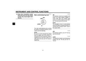 16
16 17
17 18
18 19
19 20
20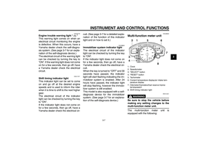 21
21 22
22 23
23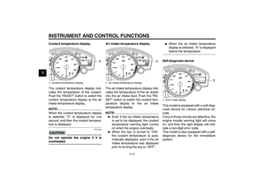 24
24 25
25 26
26 27
27 28
28 29
29 30
30 31
31 32
32 33
33 34
34 35
35 36
36 37
37 38
38 39
39 40
40 41
41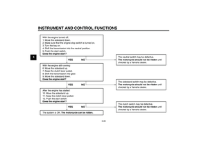 42
42 43
43 44
44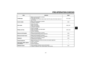 45
45 46
46 47
47 48
48 49
49 50
50 51
51 52
52 53
53 54
54 55
55 56
56 57
57 58
58 59
59 60
60 61
61 62
62 63
63 64
64 65
65 66
66 67
67 68
68 69
69 70
70 71
71 72
72 73
73 74
74 75
75 76
76 77
77 78
78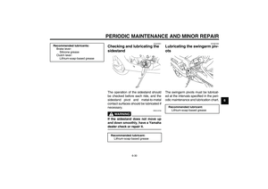 79
79 80
80 81
81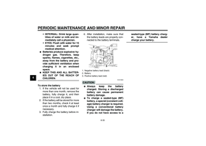 82
82 83
83 84
84 85
85 86
86 87
87 88
88 89
89 90
90 91
91 92
92 93
93 94
94 95
95 96
96 97
97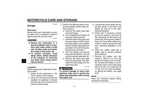 98
98 99
99 100
100 101
101 102
102 103
103 104
104 105
105 106
106 107
107