Page 57 of 108
PERIODIC MAINTENANCE AND MINOR REPAIR
6-8
6
2. Remove the projection on cowling
A from the hole in cowling B as
shown.3. Remove the forward-most projec-
tion from the slot, slide the cowling
forward, and then remove the re-
maining projections from the slots
as shown.
4. Disconnect the turn signal light
lead coupler.
1. Quick fastener screw
2. Quick fastener
1. Cowling B
2. Bolt
3. Quick fastener
1. Quick fastener
1. Quick fastener screw
2. Quick fastener
1. Cowling A
2. Cowling B
U13SE0E0.book Page 8 Monday, August 27, 2007 4:53 PM
Page 58 of 108
PERIODIC MAINTENANCE AND MINOR REPAIR
6-9
6
To install the cowling
1. Connect the turn signal light lead
coupler.2. Fit the projections into the slots,
slide the cowling rearward, and
then fit the forward-most projection
into the slot.3. Fit the projection on cowling A into
the hole in cowling B as shown.
4. Install the bolts, quick fasteners,
and quick fastener screw.
EAU39092
Cowling C
To remove the cowling1. Remove cowling B and panel B.
(See page 6-7.)
2. Unfasten the wire harness by
pressing on the projection to open
the plastic fastener.
1. Cowling A
2. Turn signal light lead coupler
1. Cowling B
2. Turn signal light lead coupler
1. Cowling A
2. Turn signal light lead coupler
1. Cowling B
2. Turn signal light lead coupler
1. Cowling A
2. Cowling B
U13SE0E0.book Page 9 Monday, August 27, 2007 4:53 PM
Page 59 of 108
PERIODIC MAINTENANCE AND MINOR REPAIR
6-10
6 3. Remove the bolts and the quick
fastener, and then pull the cowling
off as shown.To install the cowling
1. Fit the slot in cowling C over the
projection on the front cowling.
2. Install the bolts and the quick fas-
tener.
3. Place the wire harness in the orig-
inal position, and then close the
plastic fastener.
4. Install the cowling and the panel.
EAU39060
Panels A and B
To remove one of the panelsRemove the bolts, and then pull the
panel off as shown.To install the panel
Place the panel in the original position,
and then install the bolts.
1. Plastic fastener
2. Projection
3. Wire harness
1. Cowling C
2. Bolt
3. Quick fastener
1. Cowling C
2. Slot
3. Front cowling
4. Projection
1. Panel B
2. Bolt
U13SE0E0.book Page 10 Monday, August 27, 2007 4:53 PM
Page 60 of 108

PERIODIC MAINTENANCE AND MINOR REPAIR
6-11
6
EAU19652
Checking the spark plugs The spark plugs are important engine
components, which should be checked
periodically, preferably by a Yamaha
dealer. Since heat and deposits will
cause any spark plug to slowly erode,
they should be removed and checked
in accordance with the periodic mainte-
nance and lubrication chart. In addition,
the condition of the spark plugs can re-
veal the condition of the engine.
The porcelain insulator around the cen-
ter electrode of each spark plug should
be a medium-to-light tan (the ideal color
when the vehicle is ridden normally),
and all spark plugs installed in the en-
gine should have the same color. If any
spark plug shows a distinctly different
color, the engine could be operating im-
properly. Do not attempt to diagnose
such problems yourself. Instead, have
a Yamaha dealer check the vehicle.
If a spark plug shows signs of electrode
erosion and excessive carbon or other
deposits, it should be replaced.Before installing a spark plug, the spark
plug gap should be measured with a
wire thickness gauge and, if necessary,
adjusted to specification.
Clean the surface of the spark plug
gasket and its mating surface, and then
wipe off any grime from the spark plug
threads.
NOTE:If a torque wrench is not available when
installing a spark plug, a good estimate
of the correct torque is 1/4–1/2 turn
past finger tight. However, the spark
plug should be tightened to the speci-fied torque as soon as possible.CAUTION:
ECA10840
Do not use any tools to remove or in-
stall the spark plug cap, otherwise
the ignition coil coupler may get
damaged. The spark plug cap may
be difficult to remove because the
rubber seal on the end of the cap fits
tightly. To remove the spark plug
cap, simply twist it back and forth
while pulling it out; to install it, twistit back and forth while pushing it in.
Specified spark plug:
NGK/CR10EK
1. Spark plug gapSpark plug gap:
0.6–0.7 mm (0.024–0.028 in)
Tightening torque:
Spark plug:
12.5 Nm (1.25 m·kgf, 9.0 ft·lbf)
U13SE0E0.book Page 11 Monday, August 27, 2007 4:53 PM
Page 61 of 108

PERIODIC MAINTENANCE AND MINOR REPAIR
6-12
6
EAU38995
Engine oil and oil filter car-
tridge The engine oil level should be checked
before each ride. In addition, the oil
must be changed and the oil filter car-
tridge replaced at the intervals speci-
fied in the periodic maintenance and
lubrication chart.
To check the engine oil level
1. Place the vehicle on a level sur-
face and hold it in an upright posi-
tion.NOTE:
Make sure that the vehicle is positioned
straight up when checking the oil level.
A slight tilt to the side can result in afalse reading.
2. Start the engine, warm it up for
several minutes, and then turn it
off.
3. Wait a few minutes until the oil set-
tles.4. Remove the engine oil dipstick and
wipe it clean, insert it back into the
hole (without screwing it in), and
then remove it again to check the
oil level.
NOTE:The engine oil should be between theminimum and maximum level marks.
5. If the engine oil is at or below the
minimum level mark, remove the
oil filler cap, and then add sufficient
oil of the recommended type to
raise it to the correct level.6. Insert and tighten the engine oil
dipstick, and then install and tight-
en the oil filler cap.
To change the engine oil (with or
without oil filter cartridge replace-
ment)
1. Place the vehicle on a level sur-
face.
2. Remove cowling A. (See page
6-7.)
3. Start the engine, warm it up for
several minutes, and then turn it
off.
4. Place an oil pan under the engine
to collect the used oil.1. Dipstick
2. Maximum level mark
3. Minimum level mark
1. Engine oil filler cap
U13SE0E0.book Page 12 Monday, August 27, 2007 4:53 PM
Page 62 of 108
PERIODIC MAINTENANCE AND MINOR REPAIR
6-13
65. Remove the engine oil filler cap
and drain bolt to drain the oil from
the crankcase.
NOTE:
Skip steps 6–12 if the oil filter cartridgeis not being replaced.
6. Remove the shift arm by removing
the bolt and pulling it off its shaft.
7. Remove the fuel tank breath-
er/overflow hoses from the guides.8. Remove the oil filter cartridge with
an oil filter wrench.
NOTE:An oil filter wrench is available at aYamaha dealer.
9. Apply a thin coat of engine oil to
the O-ring of the new oil filter car-
tridge.NOTE:Make sure that the O-ring is properlyseated.
10. Install the new oil filter cartridge
with an oil filter wrench, and then
tighten it to the specified torque
with a torque wrench.
1. Engine oil drain bolt
1. Bolt
2. Shift arm
3. Engine oil filter cartridge
4. Guide
5. Fuel tank breather/overflow hose
1. Oil filter wrench
1. O-ring
U13SE0E0.book Page 13 Monday, August 27, 2007 4:53 PM
Page 63 of 108

PERIODIC MAINTENANCE AND MINOR REPAIR
6-14
6 11. Install the fuel tank breather/over-
flow hoses into the guides, then
place them in their original posi-
tion.
12. Install the shift arm by aligning the
match mark on the shift arm with
the match mark on the shift shaft
and installing the bolt, then tighten-
ing it to the specified torque.
CAUTION:
ECA15341
Be sure to align the match marks to
ensure proper shifting.If the match marks are not aligned,
the shift arm will not move correctly
and you may not be able to shift up
or down.
13. Install the engine oil drain bolt, and
then tighten it to the specified
torque.NOTE:Check the washer for damage and re-place it if necessary.14. Refill with the specified amount of
the recommended engine oil, and
then install and tighten the oil filler
cap.
NOTE:
Be sure to wipe off spilled oil on any
parts after the engine and exhaust sys-tem have cooled down.CAUTION:
ECA11620
�
In order to prevent clutch slip-
page (since the engine oil also
lubricates the clutch), do not
mix any chemical additives. Do
not use oils with a diesel speci-
1. Torque wrenchTightening torque:
Oil filter cartridge:
17 Nm (1.7 m·kgf, 12 ft·lbf)
1. Bolt
2. Shift shaft
3. Match marks
4. Shift arm
Tightening torque:
Shift arm bolt:
10 Nm (1.0 m·kgf, 7.2 ft·lbf)
Tightening torque:
Engine oil drain bolt:
43 Nm (4.3 m·kgf, 31 ft·lbf)
Recommended engine oil:
See page 8-1.
Oil quantity:
Without oil filter cartridge replace-
ment:
2.40 L (2.54 US qt) (2.11 Imp.qt)
With oil filter cartridge replacement:
2.60 L (2.75 US qt) (2.29 Imp.qt)
U13SE0E0.book Page 14 Monday, August 27, 2007 4:53 PM
Page 64 of 108

PERIODIC MAINTENANCE AND MINOR REPAIR
6-15
6fication of “CD” or oils of a high-
er quality than specified. In
addition, do not use oils labeled
“ENERGY CONSERVING II” or
higher.
�
Make sure that no foreign mate-rial enters the crankcase.
15. Start the engine, and then let it idle
for several minutes while checking
it for oil leakage. If oil is leaking, im-
mediately turn the engine off and
check for the cause.
NOTE:After the engine is started, the engine
oil level warning light should go off if theoil level is sufficient.CAUTION:
ECA10400
If the oil level warning light flickers
or remains on, immediately turn the
engine off and have a Yamaha dealercheck the vehicle.
16. Turn the engine off, and then
check the oil level and correct it if
necessary.
17. Install the cowling.
EAU20070
Coolant The coolant level should be checked
before each ride. In addition, the cool-
ant must be changed at the intervals
specified in the periodic maintenance
and lubrication chart.
EAU39084
To check the coolant level
1. Place the vehicle on a level sur-
face and hold it in an upright posi-
tion.NOTE:�
The coolant level must be checked
on a cold engine since the level
varies with engine temperature.
�
Make sure that the vehicle is posi-
tioned straight up when checking
the coolant level. A slight tilt to theside can result in a false reading.
2. Check the coolant level in the cool-
ant reservoir.
NOTE:The coolant should be between theminimum and maximum level marks.
1.“CD” specification
2.“ENERGY CONSERVING II”
1
2
U13SE0E0.book Page 15 Monday, August 27, 2007 4:53 PM
 1
1 2
2 3
3 4
4 5
5 6
6 7
7 8
8 9
9 10
10 11
11 12
12 13
13 14
14 15
15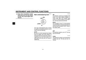 16
16 17
17 18
18 19
19 20
20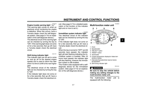 21
21 22
22 23
23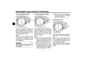 24
24 25
25 26
26 27
27 28
28 29
29 30
30 31
31 32
32 33
33 34
34 35
35 36
36 37
37 38
38 39
39 40
40 41
41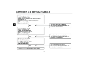 42
42 43
43 44
44 45
45 46
46 47
47 48
48 49
49 50
50 51
51 52
52 53
53 54
54 55
55 56
56 57
57 58
58 59
59 60
60 61
61 62
62 63
63 64
64 65
65 66
66 67
67 68
68 69
69 70
70 71
71 72
72 73
73 74
74 75
75 76
76 77
77 78
78 79
79 80
80 81
81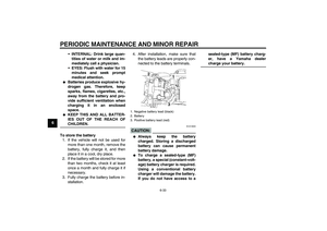 82
82 83
83 84
84 85
85 86
86 87
87 88
88 89
89 90
90 91
91 92
92 93
93 94
94 95
95 96
96 97
97 98
98 99
99 100
100 101
101 102
102 103
103 104
104 105
105 106
106 107
107


