Page 25 of 108

INSTRUMENT AND CONTROL FUNCTIONS
3-11
3 If any of the immobilizer system circuits
are defective, the immobilizer system
indicator light will flash, and then the
right display will indicate a two-digit er-
ror code.
NOTE:If the right display indicates error code
52, this could be caused by transpon-
der interference. If this error code ap-pears, try the following.
1. Use the code re-registering key to
start the engine.NOTE:Make sure there are no other immobi-
lizer keys close to the main switch, and
do not keep more than one immobilizer
key on the same key ring! Immobilizer
system keys may cause signal interfer-
ence, which may prevent the enginefrom starting.
2. If the engine starts, turn it off and
try starting the engine with the
standard keys.
3. If one or both of the standard keys
do not start the engine, take the
vehicle, the code re-registeringkey and both standard keys to a
Yamaha dealer and have the stan-
dard keys re-registered.
If the right display indicates any error
codes, note the code number, and then
have a Yamaha dealer check the vehi-
cle.
CAUTION:
ECA11590
If the display indicates an error
code, the vehicle should be checked
as soon as possible in order to avoidengine damage.Display brightness and shift timing
indicator light control mode
This mode cycles through five control
functions, allowing you to make the fol-
lowing settings in the order listed be-
low.
�
Display brightness:
This function allows you to adjust
the brightness of the displays and
tachometer to suit the outside
lighting conditions.
1. Display brightness
2. Shift timing indicator light activation/deacti-
vation
3. Shift timing indicator light
4. Brightness level
km/h
2
1
4
3
1
U13SE0E0.book Page 11 Monday, August 27, 2007 4:53 PM
Page 26 of 108

INSTRUMENT AND CONTROL FUNCTIONS
3-12
3
�
Shift timing indicator light activity:
This function allows you to choose
whether or not the indicator light
should be activated and whether it
should flash or stay on when acti-
vated.
�
Shift timing indicator light activa-
tion:
This function allows you to select
the engine speed at which the indi-
cator light will be activated.
�
Shift timing indicator light deactiva-
tion:
This function allows you to select
the engine speed at which the indi-
cator light will be deactivated.
�
Shift timing indicator light bright-
ness:
This function allows you to adjust
the brightness of the indicator light
to suit your preference.
NOTE:In this mode, the right display shows
the current setting for each function
(except the shift timing indicator lightactivity function).To adjust the brightness of the multi-
function meter displays and tachometer1. Turn the key to “OFF”.
2. Push and hold the “SELECT” but-
ton.
3. Turn the key to “ON”, and then re-
lease the “SELECT” button after
five seconds.
4. Push the “RESET” button to select
the desired brightness level.
5. Push the “SELECT” button to con-
firm the selected brightness level.
The control mode changes to the
shift timing indicator light activity
function.
To set the shift timing indicator light ac-tivity function1. Push the “RESET” button to select
one of the following indicator light
activity settings:
�
The indicator light will stay on
when activated. (This setting
is selected when the indicator
light stays on.)
�
The indicator light will flash
when activated. (This setting
is selected when the indicator
light flashes four times per
second.)
�
The indicator light is deacti-
vated; in other words, it will
not come on or flash. (This
setting is selected when the
indicator light flashes once
every two seconds.)
2. Push the “SELECT” button to con-
firm the selected indicator light ac-
tivity. The control mode changes to
the shift timing indicator light acti-
vation function.
To set the shift timing indicator light ac-
tivation functionNOTE:The shift timing indicator light activation
function can be set between 10000
r/min and 18000 r/min. From 10000
r/min to 13000 r/min, the indicator light
can be set in increments of 500 r/min.
From 13000 r/min to 18000 r/min, the
indicator light can be set in incrementsof 200 r/min.
U13SE0E0.book Page 12 Monday, August 27, 2007 4:53 PM
Page 27 of 108

INSTRUMENT AND CONTROL FUNCTIONS
3-13
3 1. Push the “RESET” button to select
the desired engine speed for acti-
vating the indicator light.
2. Push the “SELECT” button to con-
firm the selected engine speed.
The control mode changes to the
shift timing indicator light deactiva-
tion function.
To set the shift timing indicator light de-
activation functionNOTE:�
The shift timing indicator light de-
activation function can be set be-
tween 10000 r/min and 18000
r/min. From 10000 r/min to 13000
r/min, the indicator light can be set
in increments of 500 r/min. From
13000 r/min to 18000 r/min, the in-
dicator light can be set in incre-
ments of 200 r/min.
�
Be sure to set the deactivation
function to a higher engine speed
than for the activation function,
otherwise the shift timing indicatorlight will remain deactivated.1. Push the “RESET” button to select
the desired engine speed for deac-
tivating the indicator light.
2. Push the “SELECT” button to con-
firm the selected engine speed.
The control mode changes to the
shift timing indicator light bright-
ness function.
To adjust the shift timing indicator light
brightness1. Push the “RESET” button to select
the desired indicator light bright-
ness level.
2. Push the “SELECT” button to con-
firm the selected indicator light
brightness level. The right display
will return to the odometer or trip-
meter mode.
EAU12331
Anti-theft alarm (optional) This model can be equipped with an
optional anti-theft alarm by a Yamaha
dealer. Contact a Yamaha dealer for
more information.
U13SE0E0.book Page 13 Monday, August 27, 2007 4:53 PM
Page 28 of 108

INSTRUMENT AND CONTROL FUNCTIONS
3-14
3
EAU12347
Handlebar switches LeftRight
EAU12350
Pass switch“”
Press this switch to flash the headlight.
EAU12400
Dimmer switch“/”
Set this switch to“” for the high
beam and to“” for the low beam.
EAU12460
Turn signal switch“/”
To signal a right-hand turn, push this
switch to“”. To signal a left-hand
turn, push this switch to“”. When re-
leased, the switch returns to the centerposition. To cancel the turn signal
lights, push the switch in after it has re-
turned to the center position.
EAU12500
Horn switch“”
Press this switch to sound the horn.
EAU12660
Engine stop switch“/”
Set this switch to“” before starting
the engine. Set this switch to“” to
stop the engine in case of an emergen-
cy, such as when the vehicle overturns
or when the throttle cable is stuck.
EAU12710
Start switch“”
Push this switch to crank the engine
with the starter.CAUTION:
ECA10050
See page 5-1 for starting instruc-tions prior to starting the engine.
EAU41700
The engine trouble warning light will
come on when the key is turned to “ON”
and the start switch is pushed, but this
does not indicate a malfunction.
1. Pass switch“”
2. Dimmer switch“/”
3. Turn signal switch“/”
4. Horn switch“”
5. Hazard switch“”
1. Engine stop switch“/”
2. Start switch“”
U13SE0E0.book Page 14 Monday, August 27, 2007 4:53 PM
Page 29 of 108

INSTRUMENT AND CONTROL FUNCTIONS
3-15
3
EAU12733
Hazard switch“”
With the key in the “ON” or“” posi-
tion, use this switch to turn on the haz-
ard lights (simultaneous flashing of all
turn signal lights).
The hazard lights are used in case of
an emergency or to warn other drivers
when your vehicle is stopped where it
might be a traffic hazard.CAUTION:
ECA10061
Do not use the hazard lights for an
extended length of time with the en-
gine not running, otherwise the bat-tery may discharge.
EAU12820
Clutch lever The clutch lever is located at the left
handlebar grip. To disengage the
clutch, pull the lever toward the handle-
bar grip. To engage the clutch, release
the lever. The lever should be pulled
rapidly and released slowly for smooth
clutch operation.
The clutch lever is equipped with a
clutch switch, which is part of the igni-
tion circuit cut-off system. (See page
3-27.)
EAU12870
Shift pedal The shift pedal is located on the left
side of the engine and is used in com-
bination with the clutch lever when
shifting the gears of the 6-speed con-
stant-mesh transmission equipped on
this motorcycle.
1. Clutch lever
1. Shift pedal
U13SE0E0.book Page 15 Monday, August 27, 2007 4:53 PM
Page 30 of 108
INSTRUMENT AND CONTROL FUNCTIONS
3-16
3
EAU33850
Brake lever The brake lever is located at the right
handlebar grip. To apply the front
brake, pull the lever toward the handle-
bar grip.
The brake lever is equipped with a po-
sition adjusting knob. To adjust the dis-
tance between the brake lever and the
handlebar grip, turn the adjusting knob
while holding the lever pushed away
from the handlebar grip. When the de-
sired position is obtained, be sure to setit by aligning a groove on the adjusting
knob with the“” mark on the brake
lever.
EAU12941
Brake pedal The brake pedal is on the right side of
the motorcycle. To apply the rear
brake, press down on the brake pedal.
1. Brake lever
2.“” mark
3. Brake lever position adjusting knob
4. Distance between brake lever and handlebar
grip
1. Brake pedal
U13SE0E0.book Page 16 Monday, August 27, 2007 4:53 PM
Page 31 of 108

INSTRUMENT AND CONTROL FUNCTIONS
3-17
3
EAU13072
Fuel tank cap To open the fuel tank cap
Open the fuel tank cap lock cover, in-
sert the key into the lock, and then turn
it 1/4 turn clockwise. The lock will be re-
leased and the fuel tank cap can be
opened.
To close the fuel tank cap
1. Push the fuel tank cap into position
with the key inserted in the lock.
2. Turn the key counterclockwise to
the original position, remove it, and
then close the lock cover.
NOTE:The fuel tank cap cannot be closed un-
less the key is in the lock. In addition,
the key cannot be removed if the cap isnot properly closed and locked.
WARNING
EWA11090
Make sure that the fuel tank cap isproperly closed before riding.
EAU13220
Fuel Make sure that there is sufficient fuel in
the tank. When refueling, be sure to in-
sert the pump nozzle into the fuel tank
filler hole and to fill the tank to the bot-
tom of the filler tube as shown.
WARNING
EWA10880
�
Do not overfill the fuel tank, oth-
erwise it may overflow when the
fuel warms up and expands.
�
Avoid spilling fuel on the hot en-gine.
1. Fuel tank cap lock cover
2. Unlock.
1. Fuel tank filler tube
2. Fuel level
U13SE0E0.book Page 17 Monday, August 27, 2007 4:53 PM
Page 32 of 108

INSTRUMENT AND CONTROL FUNCTIONS
3-18
3
CAUTION:
ECA10070
Immediately wipe off spilled fuel
with a clean, dry, soft cloth, since
fuel may deteriorate painted surfac-es or plastic parts.
EAU13390
CAUTION:
ECA11400
Use only unleaded gasoline. The use
of leaded gasoline will cause severe
damage to internal engine parts,
such as the valves and piston rings,as well as to the exhaust system.
Your Yamaha engine has been de-
signed to use premium unleaded gaso-
line with a research octane number of
95 or higher. If knocking (or pinging) oc-curs, use a gasoline of a different
brand. Use of unleaded fuel will extend
spark plug life and reduce maintenance
costs.
EAU39450
Fuel tank breather/overflow
hose Before operating the motorcycle:�
Check the fuel tank breather/over-
flow hose connection.
�
Check the fuel tank breather/over-
flow hose for cracks or damage,
and replace it if damaged.
�
Make sure that the end of the fuel
tank breather/overflow hose is not
blocked, and clean it if necessary.
Recommended fuel:
PREMIUM UNLEADED GASOLINE
ONLY
Fuel tank capacity:
17.3 L (4.57 US gal) (3.81 Imp.gal)
Fuel reserve amount (when the fuel
level warning light comes on):
3.5 L (0.92 US gal) (0.77 Imp.gal)
1. Fuel tank breather/overflow hose
U13SE0E0.book Page 18 Monday, August 27, 2007 4:53 PM
 1
1 2
2 3
3 4
4 5
5 6
6 7
7 8
8 9
9 10
10 11
11 12
12 13
13 14
14 15
15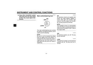 16
16 17
17 18
18 19
19 20
20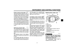 21
21 22
22 23
23 24
24 25
25 26
26 27
27 28
28 29
29 30
30 31
31 32
32 33
33 34
34 35
35 36
36 37
37 38
38 39
39 40
40 41
41 42
42 43
43 44
44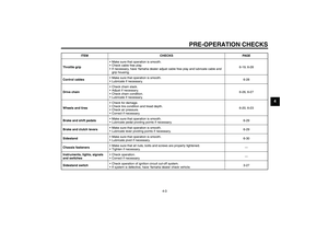 45
45 46
46 47
47 48
48 49
49 50
50 51
51 52
52 53
53 54
54 55
55 56
56 57
57 58
58 59
59 60
60 61
61 62
62 63
63 64
64 65
65 66
66 67
67 68
68 69
69 70
70 71
71 72
72 73
73 74
74 75
75 76
76 77
77 78
78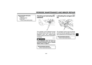 79
79 80
80 81
81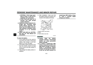 82
82 83
83 84
84 85
85 86
86 87
87 88
88 89
89 90
90 91
91 92
92 93
93 94
94 95
95 96
96 97
97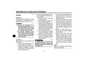 98
98 99
99 100
100 101
101 102
102 103
103 104
104 105
105 106
106 107
107