Page 250 of 496

Radio
Turn the knob clockwise to step up the
frequency. Turn the knob counterclockwise
to step down the frequency.
XM
� Satellite Radio∗�
Turn the �TUNE·FIL")
238
TUNE·FILE (Tuning and File up/down)
Radio
Turn the knob clockwise to step up the
frequency. Turn the knob counterclockwise
to step down the frequency.
XM
� Satellite Radio∗�
Turn the �TUNE·FILE" knob clockwise to
step up the channel. Turn the knob coun-
terclockwise to step down the channel.
∗: Use of satellite radio r equires XM�
tuner and service. Contact your Toyota
dealer for details.
MP3/WMA player
Turn the knob clockwise to file up. Turn
the knob counterclockwise to file down.
TYPE
XM
� Satellite Radio∗�
When you push the �� " or ��" side of
the �TYPE" button while receiving a XM
�
channel, the current channel category ap-
pears on the display.
When the channel category appears, push
either � �" or � �" side of the �TYPE" but-
ton to switch to the next or previous cate-
gory.
∗: Use of satellite radio r equires XM�
tuner and service. Contact your Toyota
dealer for details.
CY17029
Some parts of the audio system can be
adjusted using the switches on the steer-
ing wheel.
Details of the specific switches, controls,
and features are described below.
1. Volume control switches
2. � ��" switch
3. �MODE" switch 1. Volume control switches
Push the �+" side to increase the volume.
The volume continues to increase while
the switch is being pushed.
Push the �−" side to decrease the volume.
The volume continues to decrease while
the switch is being pushed. 2. � � � " switch
Radio
This switch has the following features�
To select a preset station:
Quickly push and release the � �" or � �"
side of the switch. Do this again to select
the next preset station.
To seek a station:
Push and hold the � �" or � �" side of the
switch until you hear a beep. Do this
again to find the next station. If you push
the switch on either side during the seek
mode, seeking will be cancelled.
To step up or down the frequency, push
and hold the switch even after you hear
a beep. When you release the switch, the
radio will begin seeking up or down for a
station. Do this again to find the next
station.
Audio remote controls
(steering switches)
Page 316 of 496
304
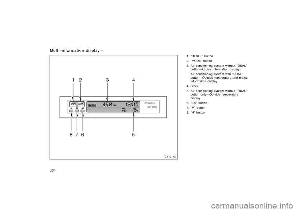
1. �RESET" button
2. �MODE" button
3. Air conditioning system without �DUAL"button�Cruise information display
Air conditioning system with �DUAL"
button�Outside temperature and cruise
information display
4. Clock
5. Air conditioning system without �DUAL" button only�Outside temperature
display
6. �:00" button
7. �M" button
8. �H" button
Multi−information display�
CY19142
Page 317 of 496

305
Operate the multi−information display
with the engine switch on.
When the engine switch is turned to �ON",
the last previously used mode displayed
just before the engine switch is turned off
will appear.
If the electrical power source has been
disconnected from the multi−information
display, the display will automatically be
set to the initial mode.
CAUTION
Do not adjust the display while the
vehicle is moving. Be sure to adjust
the display only when the vehicle is
stopped.
CY19001
To reset the hour: Push the �H" button.
To reset the minutes: Push the �M" button.
If quick adjustment to a full hour is de-
sired, push the �:00" button.
For example, if the �:00" button is de-
pressed when the time is between
1:01�1:29, the time will change to 1:00.
If the time is between 1:30�1:59, the
time will change to 2:00.
The engine switch must be in the �ACC"
or �ON" position.
If the electrical power source has been
disconnected from the clock, the time dis-
play will automatically be set to 1:00 (one
o’clock).
CY19082
The displayed temperature ranges from
−30�C (−22 �F) up to 50 �C (122 �F).
The engine switch must be in the �ON"
position.
If an abnormality exists in the connection
of the outside air temperature sensor,
�−− �C" (�−− �F") will appear on the display.
If �−− �C" (�−− �F") appears on the display,
contact your Toyota dealer.
There may be a case that �−− �C" (�−− �F")
appears momentarily when the engine
switch is quickly turned to �ON". It is
normal if it goes out soon.
�Before using the
multi−information display �Clock
�Outside temperature display
(air conditioning system
without �DUAL" button)
Page 329 of 496

317
NOTICE
�To prevent the battery from being
discharged, do not use the power
outlet longer than necessary when
the engine is not running.
� Close the power outlet lid when the
power outlet is not in use. Inserting
anything other than an appropriate
plug that fits the outlet may cause
electrical failure or short circuits.
The power outlet is not designed for
the following electric appliances even
though their power consumption is un-
der 115 VAC/100W. These appliances
may not operate properly.
�Appliances with high initial peak watt-
age: cathode−ray tube type televisions,
compressor−driven refrigerators, electric
pumps, electric tools, etc.
�Measuring devices which process pre-
cise data: medical equipment, measur-
ing instruments, etc.
�Other appliances requiring an extremely
stable power supply: microcomputer−
controlled electric blankets, touch sen-
sor lamps, etc.
Certain electrical appliances may cause
radio noise.
CY19127
To use the glove box:
Open by pulling the lever.
Lock by inserting the master key and turn-
ing it clockwise.
Unlock by inserting the master key and
turning it counterclockwise.
With the instrument panel lights on, the
glove box light will come on.
CAUTION
To reduce the chance of injury in
case of an accident or a sudden stop,
always keep the glove box door
closed while driving.
Glove box
Page 347 of 496
 attached to the roof and
sliding cross rails (2).
To adjust the positions of cross rails, do
this.1. Turn the knobs counterclockwise to loosen")
335
The roof luggage carrier consists of
roof rails (1) attached to the roof and
sliding cross rails (2).
To adjust the positions of cross rails, do
this.1. Turn the knobs counterclockwise to loosen the cross rails.
2. Slide the cross rails to the desired position for loading the luggages of
various sizes.
3. After adjusting, be sure to tighten the cross rails by turning knobs clockwise.
Follow the manufacturer ’s instructions and
precautions when installing the attach-
ments or their equivalent.
When there is no luggage on the roof
luggage carrier, Toyota recommends that
the front and rear cross rails be secured
in the positions indicated in the illustra-
tion, according to the following procedure.
This may diminish wind noise during driv-
ing.CAUTION
When you load cargo on the roof lug-
gage carrier, observe the following:
�Place the cargo so that its weight
is distributed evenly between the
front and rear axles.
�If loading long or wide cargo, never
exceed the vehicle overall length or
width. (See �Dimensions and
weights" on page 462 in Section 8
for information on your vehicle
overall length and width.)
�Before driving, make sure the cargo
is securely fastened on the roof
luggage carrier.
�Loading cargo on the roof luggage
carrier will make the center of the
vehicle gravity higher. Avoid high
speeds, sudden starts, sharp turns,
sudden braking or abrupt maneu-
vers, otherwise it may result in loss
of control or vehicle rollover due to
failure to operate this vehicle cor-
rectly.
�If driving for a long distance, on
rough roads, or at high speeds,
stop the vehicle now and then dur-
ing the trip to make sure the cargo
remains in its place.
�Do not exceed 54 kg (120 lb.) cargo
weight on the roof luggage carrier.
NOTICE
When loading the luggages, be careful
not to scratch the surface of the
moon roof.
Page 410 of 496

398
CY40047
2. Insert the end of the jack handleextension into the lowering screw
and turn it counterclockwise with
the handle.
3. After the tire is lowered completely to the ground, remove the holding
bracket.
When storing the spare tire, put it in
place with the outer side of the wheel
facing up. Then secure the tire, taking
care that the tire goes straight up
without catching on any other part, to
prevent it from flying forward during
a collision or sudden braking.
CY40011
2. Block the wheel diagonally op- posite the flat tire to keep the
vehicle from rolling when it is
jacked up.
When blocking the wheel, place a
wheel block in front of one of the front
wheels or behind one of the rear
wheels.
CY40020
3. Remove the wheel ornament.
Pry off the wheel ornament, using the
beveled end of the wheel nut wrench
as shown.
CAUTION
Do not try to pull off the orna-
ment by hand. Take due care in
handling the ornament to avoid
unexpected personal injury.
�Blocking the wheel �Removing wheel ornament
Page 411 of 496
399
CY40021
4. Loosen all the wheel nuts.
Always loosen the wheel nuts before
raising the vehicle.
Turn the wheel nuts counterclockwise
to loosen. To get maximum leverage,
fit the wrench to the nut so that the
handle is on the right side, as shown
above. Grab the wrench near the end
of the handle and pull up on the han-
dle. Be careful that the wrench does
not slip off the nut.
Do not remove the nuts yet�just un-
screw them about one−half turn.
CAUTION
Never use oil or grease on the
bolts or nuts. The nuts may loose
and the wheels may fall off,
which could cause a serious ac-
cident.
CY40059
���
�� ���
�
5. Position the jack at the correct
jack point as shown.
Make sure the jack is positioned on
a level and solid place.
JACK POINTS: Front�Under the frame side rail
Rear�Under the rear axle housing
�Loosening wheel nuts �Positioning the jack
Page 413 of 496
401
CY40058
7. Raise the vehicle high enoughso that the spare tire can be
installed.
Remember you will need more ground
clearance when putting on the spare
tire than when removing the flat tire.
To raise the vehicl e, insert the jack
handle end into the jack (it is a loose
fit) and turn it clockwise with the han-
dle.
CAUTION
Never get under the vehicle when
the vehicle is supported by the
jack alone.
CY40022
8. Remove the wheel nuts and
change tires.
Lift the flat tire straight off and put it
aside.
Roll the spare wheel into position and
align the holes in the wheel with the
bolts. Then lift up the wheel and get
at least the top bolt started through
its hole. Wiggle the tire and press it
back over the other bolts.
�Changing wheels