2008 SUBARU TRIBECA ECO mode
[x] Cancel search: ECO modePage 127 of 409
The odometer/trip meter will also go off if
you open and close the driver’sdoor
within 10 seconds of illumination of the
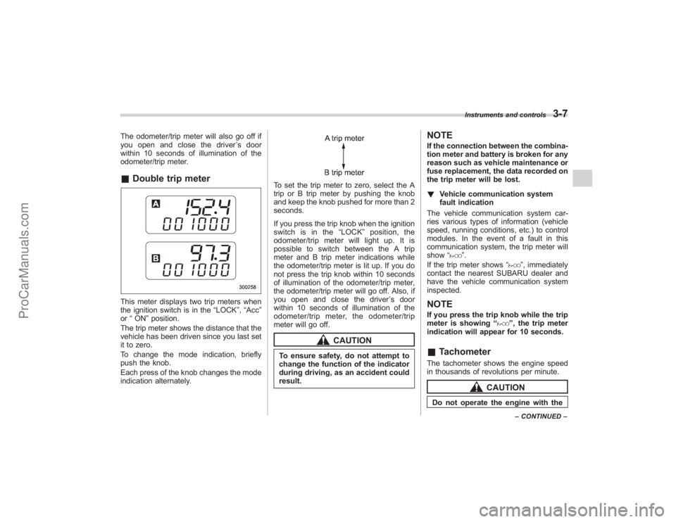
odometer/trip meter.& Double trip meterThis meter displays two trip meters when
the ignition switch is in the “LOCK”,“Acc ”
or “ON ”position.
The trip meter shows the distance that the
vehicle has been driven since you last set
it to zero.
To change the mode indication, briefly
push the knob.
Each press of the knob changes the mode
indication alternately.
To set the trip meter to zero, select the A
trip or B trip meter by pushing the knob
and keep the knob pushed for more than 2
seconds.
If you press the trip knob when the ignition
switch is in the “LOCK ”position, the
odometer/trip meter will light up. It is
possible to switch between the A trip
meter and B trip meter indications while
the odometer/trip meter is lit up. If you do
not press the trip knob within 10 seconds
of illumination of the odometer/trip meter,
the odometer/trip meter will go off. Also, if
you open and close the driver ’sdoor
within 10 seconds of illumination of the
odometer/trip meter, the odometer/trip
meter will go off.
CAUTION
To ensure safety, do not attempt to
change the function of the indicator
during driving, as an accident could
result.
NOTEIf the connection between the combina-
tion meter and battery is broken for any
reason such as vehicle maintenance or
fuse replacement, the data recorded on
the trip meter will be lost.
! Vehicle communication system
fault indication
The vehicle communication system car-
ries various types of information (vehicle
speed, running conditions, etc.) to control
modules. In the event of a fault in this
communication system, the trip meter will
show “
”.
If the trip meter shows “
”, immediately
contact the nearest SUBARU dealer and
have the vehicle communication system
inspected.
NOTEIf you press the trip knob while the trip
meter is showing “
”, the trip meter
indication will appear for 10 seconds.
& TachometerThe tachometer shows the engine speed
in thousands of revolutions per minute.
CAUTION
Do not operate the engine with the
Instruments and controls
3-7
–CONTINUED –
ProCarManuals.com
Page 129 of 409

&Temperature gauge1) Normal operating rangeThe temperature gauge shows engine
coolant temperature when the ignition
switch is in the “ON”position.
The coolant temperature will vary in
accordance with the outside temperature
and driving conditions.
We recommend that you drive moderately
until the pointer of the temperature gauge
reaches near the middle of the range.
Engine operation is optimum with the
engine coolant at this temperature range.
Also, high revving operation while the
engine is not sufficiently warmed up
should be avoided.
CAUTION
If the pointer exceeds the normal
operating range, safely stop the
vehicle as soon as possible.
Refer to “In case of emergency ”in
chapter 9.
Warning and indicator lightsSeveral of the warning and indicator lights
come on momentarily and then go out
when the ignition switch is initially turned
to the “ON ”position. This permits check-
ing the operation of the bulbs.
Apply the parking brake and turn the
ignition switch to the “ON ”position. The
following lights come on:
: Driver ’s seatbelt warning light
(The seatbelt warning light goes out
only when the driver fastens the
seatbelt.): Front passenger ’s seatbelt warning
light
(The seatbelt warning light goes out
only when the front seat passenger
fastens the seatbelt.): SRS airbag system warning light: CHECK ENGINE warning light/ Malfunction indicator lamp: Charge warning light: Oil pressure warning light: AT OIL temperature warning light/
: ABS warning light
: Vehicle Dynamics Control operation
Instruments and controls
3-9
–CONTINUED –
ProCarManuals.com
Page 130 of 409
3-10
Instruments and controls
indicator light: Vehicle Dynamics Control warninglight/Traction Control system OFF
indicator light/
: Brake system warning light
: All-Wheel Drive warning light: Low tire pressure warning light: SPORT mode indicator light: Front passenger ’s frontal airbag ON
indicator light: Front passenger ’s frontal airbag OFF
indicator light: Low fuel warning light: Cruise control indicator light: Cruise control set indicator light: Rear differential oil temperature warning light: Windshield washer fluid warning light: Door open warning light: Security indicator light
If any lights fail to come on, it indicates a
burned-out bulb or a malfunction of the
corresponding system.
Consult your authorized SUBARU dealer for repair.
&
Seatbelt warning light
and chime
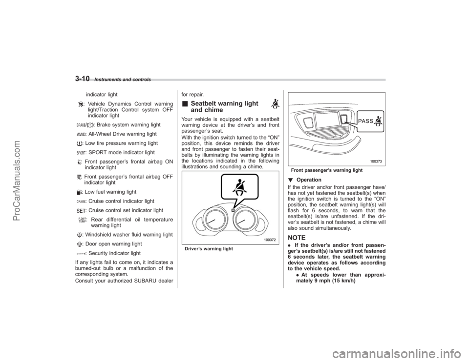
Your vehicle is equipped with a seatbelt
warning device at the driver
’s and front
passenger ’s seat.
With the ignition switch turned to the “ON”
position, this device reminds the driver
and front passenger to fasten their seat-
belts by illuminating the warning lights in
the locations indicated in the following
illustrations and sounding a chime.Driver ’s warning light
Front passenger ’s warning light! Operation
If the driver and/or front passenger have/
has not yet fastened the seatbelt(s) when
the ignition switch is turned to the “ON”
position, the seatbelt warning light(s) will
flash for 6 seconds, to warn that the
seatbelt(s) is/are unfastened. If the dri-
ver ’s seatbelt is not fastened, a chime will
also sound simultaneously.NOTE. If the driver ’s and/or front passen-
ger ’s seatbelt(s) is/are still not fastened
6 seconds later, the seatbelt warning
device operates as follows according
to the vehicle speed.
.At speeds lower than approxi-
mately 9 mph (15 km/h)
ProCarManuals.com
Page 140 of 409
3-20
Instruments and controls
section in chapter 2.)
If the indicator light does not flash, it may
indicate that immobilizer system may be
faulty. Contact your nearest SUBARU
dealer immediately.
In the event that an unauthorized key (for
example, an unauthorized duplicate) is
used, the security indicator light comes
on.&
SPORT mode indicator
light
This light comes on when the ignition
switch is turned to the“ON”position and
goes out after the engine has started.
When the selector lever is moved to the
manual gate, the SPORT mode is se-
lected and the indicator light comes on.
(Refer to the “Automatic transmission ”
section in chapter 7.)
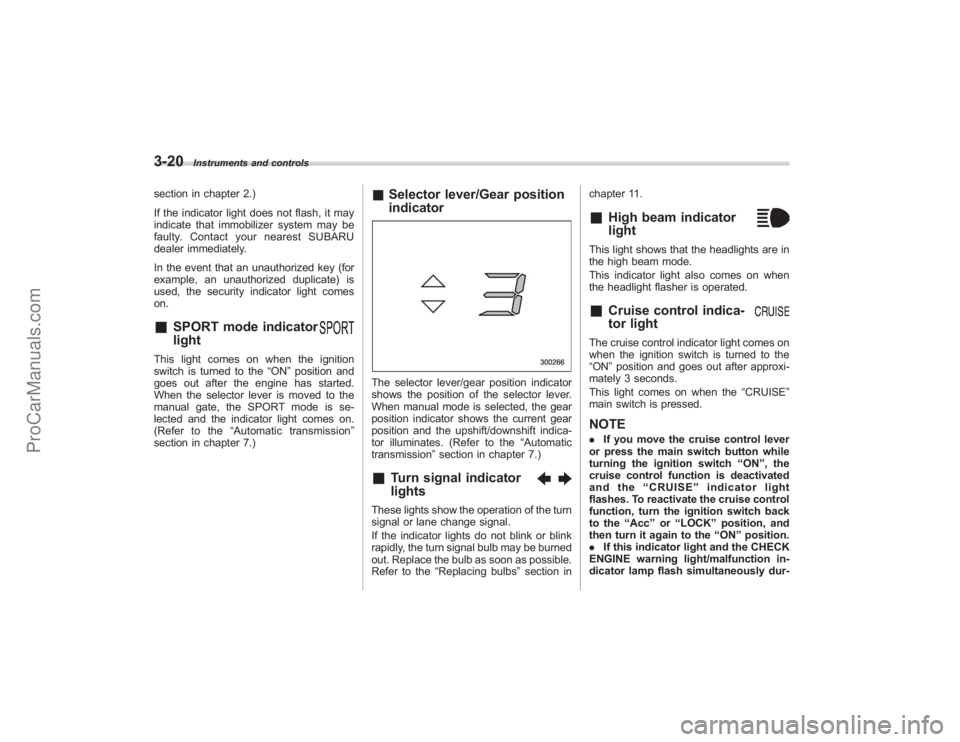
& Selector lever/Gear position
indicatorThe selector lever/gear position indicator
shows the position of the selector lever.
When manual mode is selected, the gear
position indicator shows the current gear
position and the upshift/downshift indica-
tor illuminates. (Refer to the “Automatic
transmission” section in chapter 7.)&
Turn signal indicator
lights
These lights show the operation of the turn
signal or lane change signal.
If the indicator lights do not blink or blink
rapidly, the turn signal bulb may be burned
out. Replace the bulb as soon as possible.
Refer to the“Replacing bulbs ”section in chapter 11.
&
High beam indicator
light
This light shows that the headlights are in
the high beam mode.
This indicator light also comes on when
the headlight flasher is operated.&
Cruise control indica-
tor light
The cruise control indicator light comes on
when the ignition switch is turned to the
“ON
”position and goes out after approxi-
mately 3 seconds.
This light comes on when the “CRUISE”
main switch is pressed.NOTE. If you move the cruise control lever
or press the main switch button while
turning the ignition switch “ON ”, the
cruise control function is deactivated
and the “CRUISE ”indicator light
flashes. To reactivate the cruise control
function, turn the ignition switch back
to the “Acc ”or “LOCK ”position, and
then turn it again to the “ON ”position.
. If this indicator light and the CHECK
ENGINE warning light/malfunction in-
dicator lamp flash simultaneously dur-
ProCarManuals.com
Page 159 of 409
other similar items. Periodically wipe the
sensors clean using a piece of dry soft
cotton cloth or an applicator.
!Compass calibration
1. For optimum calibration, switch off all
nonessential electrical accessories (rear
window defogger, heater/air conditioning
system, spotlight, etc.) and ensure all
doors are shut.
2. Drive to an open, level area away from
large metallic objects or structures and
make certain the ignition switch is in the
“ON ”position.
3. Press and hold the left button for 3
seconds then release, and the compass
will enter the calibration mode. “CAL”and
direction will be displayed.
4. Drive slowly in a circle until “CAL”
disappears from the display (approxi-
mately two or three circles). The compass
is now calibrated.
5. Further calibration may be necessary
should outside influences cause the mirror
to read inaccurately. You will know that
this has occurred if your compass begins
to read in only limited directions. Should
you encounter this situation, return to step
one of the above procedure and recali-
brate the mirror. !
Compass zone adjustment
1. The zone setting is factory preset to
Zone 8. Refer to the “Compass calibration
zone” map attached to the end of this
manual to verify that the compass zone
setting is correct for your geographical
location.
2. Press and hold the right button for 3
seconds then release, and the word
“ZONE ”will briefly appear and then the
zone number will be displayed.
3. Press the right-hand button repeatedly
to cycle the display through all possible
zone settings. Stop cycling when the
correct zone setting for your location is
displayed.
4. Releasing the button for 3 seconds will
exit the zone setting mode.
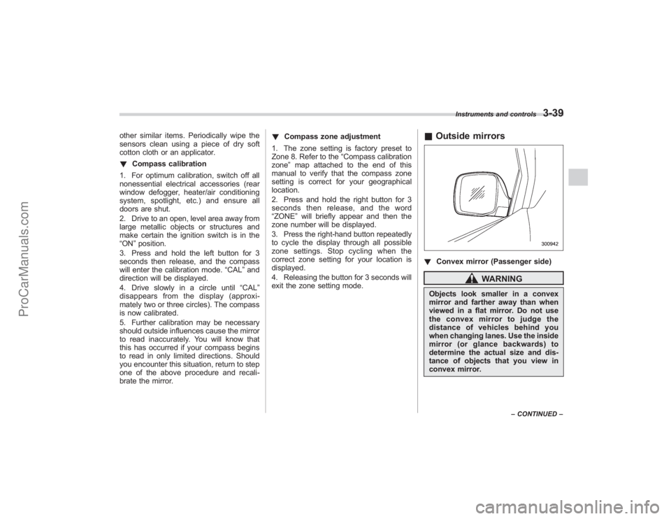
& Outside mirrors! Convex mirror (Passenger side)
WARNING
Objects look smaller in a convex
mirror and farther away than when
viewed in a flat mirror. Do not use
the convex mirror to judge the
distance of vehicles behind you
when changing lanes. Use the inside
mirror (or glance backwards) to
determine the actual size and dis-
tance of objects that you view in
convex mirror.
Instruments and controls
3-39
–CONTINUED –
ProCarManuals.com
Page 161 of 409
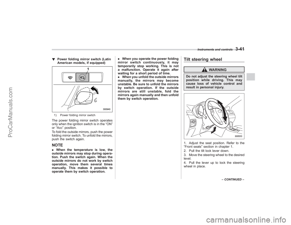
!Power folding mirror switch (Latin
American models, if equipped)1) Power folding mirror switchThe power folding mirror switch operates
only when the ignition switch is in the “ON”
or “Acc ”position.
To fold the outside mirrors, push the power
folding mirror switch. To unfold the mirrors,
push the switch again.NOTE. When the temperature is low, the
outside mirrors may stop during opera-
tion. Push the switch again. When the
outside mirrors do not work by switch
operation, move them several times
manually. This makes it possible to
operate them by switch operation. .
When you operate the power folding
mirror switch continuously, it may
temporarily stop working. This is not
a malfunction. Operate it again after
waiting for a short period of time.
. When you unfold the outside mirrors
manually, the mirrors may become
unstable. Be sure to unfold the mirrors
by switch operation. If the outside
mirrors are still unstable, fold the
mirrors again manually and then unfold
them by switch operation.
Tilt steering wheel
WARNING
Do not adjust the steering wheel tilt
position while driving. This may
cause loss of vehicle control and
result in personal injury.1. Adjust the seat position. Refer to the
“Front seats ”section in chapter 1.
2. Pull the tilt lock lever down.
3. Move the steering wheel to the desired
level.
4. Pull the lever up to lock the steering
wheel in place.
Instruments and controls
3-41
– CONTINUED –
ProCarManuals.com
Page 171 of 409
position. The fan speed of the rear air
conditioner can be adjusted using the rear
air conditioner dial behind the center
console. The fan speed can be adjusted
in four steps by turning the dial. Turn the
dial to the“OFF ”position to stop the fan.NOTE. When the “A/C ”button is in the
“ OFF ”position and when the “A/C ”
indicator is not illuminated during
AUTO mode operation, the air condi-
tioner compressor does not operate,
meaning that the system merely blows
uncooled air out of the ventilators.
. The outlet air temperature of the rear
air conditioner cannot be adjusted.
. The rear air conditioner cannot be
used as a heater.
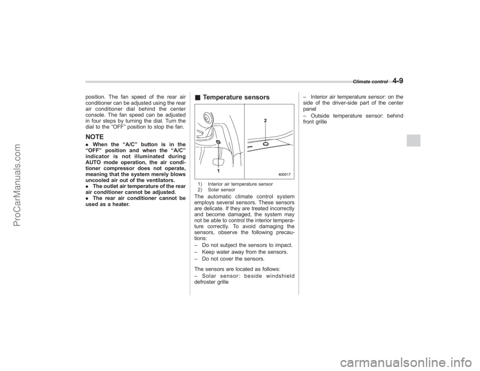
& Temperature sensors1) Interior air temperature sensor
2) Solar sensorThe automatic climate control system
employs several sensors. These sensors
are delicate. If they are treated incorrectly
and become damaged, the system may
not be able to control the interior tempera-
ture correctly. To avoid damaging the
sensors, observe the following precau-
tions:
– Do not subject the sensors to impact.
– Keep water away from the sensors.
– Do not cover the sensors.
The sensors are located as follows:
– Solar sensor: beside windshield
defroster grille –
Interior air temperature sensor: on the
side of the driver-side part of the center
panel
– Outside temperature sensor: behind
front grille
Climate control
4-9
ProCarManuals.com
Page 181 of 409
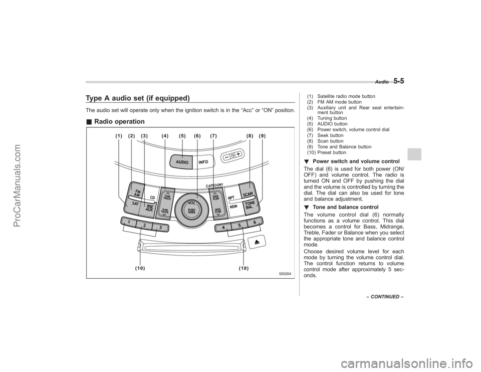
Type A audio set (if equipped)The audio set will operate only when the ignition switch is in the“Acc”or “ON ”position.& Radio operation
(1) Satellite radio mode button
(2) FM AM mode button
(3) Auxiliary unit and Rear seat entertain-
ment button
(4) Tuning button
(5) AUDIO button
(6) Power switch, volume control dial
(7) Seek button
(8) Scan button
(9) Tone and Balance button
(10) Preset button! Power switch and volume control
The dial (6) is used for both power (ON/
OFF) and volume control. The radio is
turned ON and OFF by pushing the dial
and the volume is controlled by turning the
dial. The dial can also be used for tone
and balance adjustment.
! Tone and balance control
The volume control dial (6) normally
functions as a volume control. This dial
becomes a control for Bass, Midrange,
Treble, Fader or Balance when you select
the appropriate tone and balance control
mode.
Choose desired volume level for each
mode by turning the volume control dial.
The control function returns to volume
control mode after approximately 5 sec-
onds.
Audio
5-5
– CONTINUED –
ProCarManuals.com