2008 SUBARU TRIBECA ECO mode
[x] Cancel search: ECO modePage 247 of 409
collected and stored in memory to
allow the transmission to shift at the
most appropriate times for the current
condition of your vehicle. Optimized
shifting will be restored as the vehicle
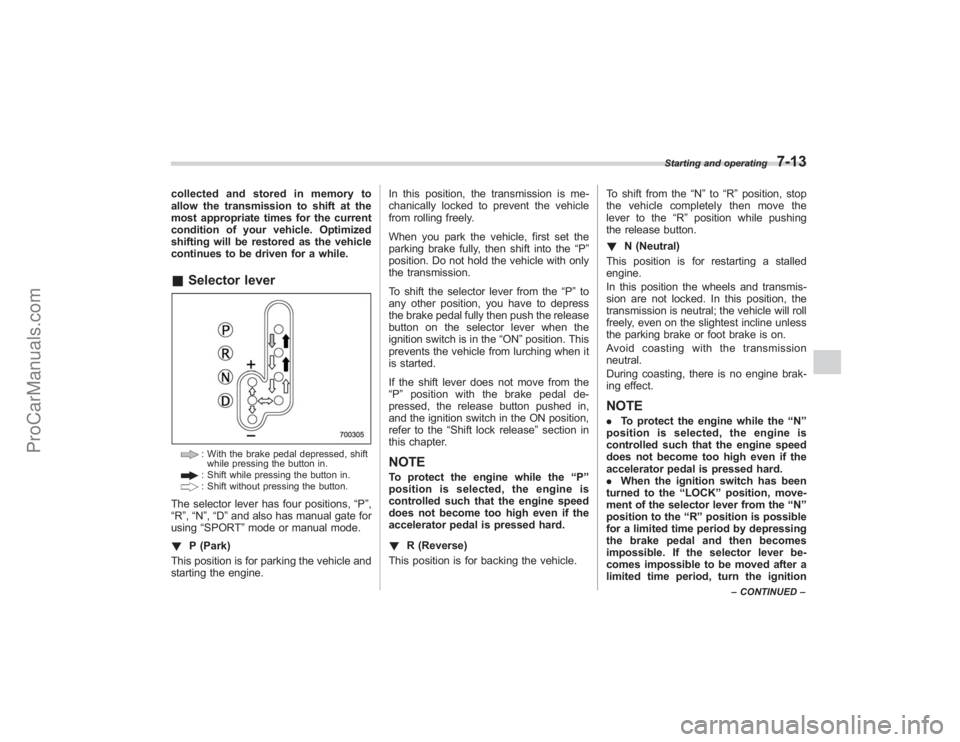
continues to be driven for a while.&Selector lever
: With the brake pedal depressed, shift
while pressing the button in.: Shift while pressing the button in.: Shift without pressing the button.
The selector lever has four positions, “P”,
“R ”,“N ”,“D ”and also has manual gate for
using “SPORT ”mode or manual mode.
! P (Park)
This position is for parking the vehicle and
starting the engine. In this position, the transmission is me-
chanically locked to prevent the vehicle
from rolling freely.
When you park the vehicle, first set the
parking brake fully, then shift into the
“P”
position. Do not hold the vehicle with only
the transmission.
To shift the selector lever from the “P”to
any other position, you have to depress
the brake pedal fully then push the release
button on the selector lever when the
ignition switch is in the “ON”position. This
prevents the vehicle from lurching when it
is started.
If the shift lever does not move from the
“ P ” position with the brake pedal de-
pressed, the release button pushed in,
and the ignition switch in the ON position,
refer to the “Shift lock release ”section in
this chapter.
NOTETo protect the engine while the “P ”
position is selected, the engine is
controlled such that the engine speed
does not become too high even if the
accelerator pedal is pressed hard.
! R (Reverse)
This position is for backing the vehicle. To shift from the
“N ”to “R”position, stop
the vehicle completely then move the
lever to the “R”position while pushing
the release button.
! N (Neutral)
This position is for restarting a stalled
engine.
In this position the wheels and transmis-
sion are not locked. In this position, the
transmission is neutral; the vehicle will roll
freely, even on the slightest incline unless
the parking brake or foot brake is on.
Avoidcoastingwiththetransmission
neutral.
During coasting, there is no engine brak-
ing effect.
NOTE. To protect the engine while the “N ”
position is selected, the engine is
controlled such that the engine speed
does not become too high even if the
accelerator pedal is pressed hard.
. When the ignition switch has been
turned to the “LOCK ”position, move-
ment of the selector lever from the “N ”
position to the “R ” position is possible
for a limited time period by depressing
the brake pedal and then becomes
impossible. If the selector lever be-
comes impossible to be moved after a
limited time period, turn the ignition
Starting and operating
7-13
– CONTINUED –
ProCarManuals.com
Page 248 of 409
7-14
Starting and operating
switch to the“ON ”position. You will
then be able to move the selector lever
to the “P ” position.
WARNING
Do not drive the vehicle with the
selector lever in the “N ” (neutral)
position. Engine braking has no
effect in this condition and the risk
of an accident is consequently in-
creased.
! D (Drive)
This position is for normal driving.
The transmission automatically shifts into
a suitable gear from 1st to 5th according to
the vehicle speed and the acceleration
you require.
When more acceleration is required in this
position, press the accelerator pedal fully
to the floor and hold that position. The
transmission will automatically downshift
to 4th, 3rd, 2nd or 1st gear. When you
release the pedal, the transmission will
return to the original gear position.
To use the SPORT mode, move the lever
from this position into the manual gate.
To use the manual mode, move the lever
from this position into the manual gate
then move it toward the “+”and “−”ends. !
While climbing a grade
When driving up a hill, undesired upshift to
4th or 5th gear is prevented from taking
place when the accelerator is released.
This minimizes the chance of subsequent
downshifting to a lower gear when accel-
erating again. This prevents repeated
upshifting and downshifting resulting in a
smoother operation of the vehicle.
NOTEThe transmission may downshift to 2nd
or 1st gear, depending on the way the
accelerator pedal is pressed to accel-
erate the vehicle again.& Selector lever reverse inhi-
biting functionThis function prevents accidental move-
ment of the selector lever to the “R ”
position while the vehicle is moving.
The function becomes operational when
the vehicle reaches a speed of approxi-
mately 6 mph (10 km/h). Once opera-
tional, it prevents the selector lever from
being moved from the “N”position to the
“ R ” position. When the vehicle speed
drops below 6 mph (10 km/h), the function
is canceled. The selector lever can then
be moved to the “R”and “P”positions.
When the ignition switch has been turned to the
“LOCK” position, movement of the
selector lever from the “N ”position to the
“R ”position is possible for a limited time
period by depressing the brake pedal and
then becomes impossible. Also, the se-
lector lever cannot be moved to the “R”
position after it has been placed in the “P ”
position and then placed again in the “N”
position.
When the movement of the selector lever
from the “N”position to the “R ” position
has become impossible, turn the ignition
switch back to the “ON”position then
move the selector lever to the “P”position.
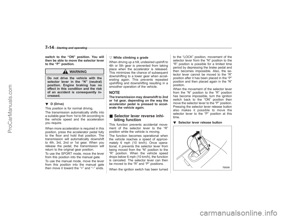
Pressing the selector lever release button
alsomakesitpossibletomovethe
selector lever to the “P ” position at this
time.
! Selector lever release button
ProCarManuals.com
Page 250 of 409
7-16
Starting and operating
.The transmission does not automa-
tically shift up in the manual mode.
Perform gearshifts in accordance with
road conditions so that the tachometer
needle does not enter the red zone. If
the engine speed reaches a predeter-
mined level, a fuel-cut function will
operate. Shift up if this happens. Also,
the transmission may automatically
shift up to protect the engine.
. If you attempt to shift down when
the engine speed is too high, i.e., when
a downshift would push the tachometer
needle beyond the red zone, beeps will
be emitted to warn you that the down-
shift is not possible.
. If you attempt to shift up when the
vehicle speed is too low, the transmis-
sion will not respond.
. You can perform a skip-shift (for
example, from 4th to 2nd) by operating
the selector lever twice in rapid suc-
cession.
. The transmission automatically se-
lects 1st gear when the vehicle stops
moving.
. If the temperature of the automatic
transmission fluid becomes too high,
the “AT OIL TEMP ”warning light will
come on and upshifts to 5th gear will
not be possible. Immediately stop the
vehicle in a safe place and let the
engine idle until the warning light goes off.
&
Maximum speeds
WARNING
When down shifting, ensure that the
vehicle is not travelling at a speed
exceeding the Maximum Allowable
Speed for the gear which is about to
be selected. Failure to observe this
precaution can lead to engine over-
revving and this in turn can result in
engine damage.
In addition, sudden application of
engine braking caused by down
shifting when the vehicle is travel-
ling on a slippery surface can lead
to wheel locking; as a consequence,
control of the vehicle may be lost
and the risk of an accident in-
creased.
The following tables show the maximum
speeds that are possible with each differ-
ent gear.
When down shifting, it is important to
confirm that the current vehicle speed is
not in excess of the Maximum Allowable
Speed of the gear which is about to be
selected.
Position mph (km/h)
1 28 (45)
2 53 (85)
3 87 (140)
Never exceed posted speed limits.
NOTE. In order to prevent over-revving
during acceleration of the vehicle, the
transmission will automatically shift to
the next highest gear if the Maximum
Allowable Speed for the current gear is
exceeded.
. Similarly, in order to prevent over-
revving during deceleration of the
vehicle, the transmission will remain
in the current gear if the speed of the
vehicle is in excess of the Maximum
Allowable Speed for the gear to which
the selector lever has been moved.& Driving tips. On a road surface where there is a risk
of wheelspin (for example, a snow- or
gravel-covered road), you can pull away
from a standstill safely and easily by first
selecting the 2nd gear of the manual
mode.
. Always apply the foot or parking brake
when the vehicle is stopped in the “D”or
ProCarManuals.com
Page 260 of 409
7-26
Starting and operating
due to a malfunction in that electrical
system, the Vehicle Dynamics Control will
also become unable to control all four
brakes. Thus Vehicle Dynamics Control
system operation halts and the warning
light turns on. Although both the Vehicle
Dynamics Control system and the ABS
will be inoperable in this situation, it will
still be possible to stop the vehicle using
normal braking. The Vehicle Dynamics
Control system and the ABS do not
adversely affect operation of the vehicle
in any way when they are inoperable;
however should such a situation occur,
drive with care and have an authorized
SUBARU dealer carry out an inspection of
those systems at the first available oppor-
tunity.NOTEWhen the warning light turns on and off
in the following way, it indicates that
the Vehicle Dynamics Control system
is operating normally.
.Although turning on after the engine
has been started, the warning light
quickly turns off and stays off.
. The warning light turns on when the
vehicle is being driven; it then turns off
and stays off. !
Traction Control system OFF indica-
tor light
This light comes on to indicate that the
Traction Control system is in non-opera-
tion mode. This does not constitute failure
of the Vehicle Dynamics Control system.
NOTE. The indicator light may stay on for a
while after the engine has been started,
especially in cold weather. This occurs
because the engine has not yet
warmed up and is completely normal.
The light will turn off when the engine
has reached a suitable operating tem-
perature.
. When an engine problem occurs
and the malfunction indicator lamp
turns on, the indicator light will also
come on.
The following two situations could indicate
malfunction of the Vehicle Dynamics
Control system; if either should occur,
have an authorized SUBARU dealer carry
out an inspection of that system at the first
available opportunity.
. The indicator light does not turn on
when the ignition key is turned to the ON
position.
. The indicator light fails to turn off after
the engine is started, even when several
minutes have passed to allow the engine to heat up sufficiently.
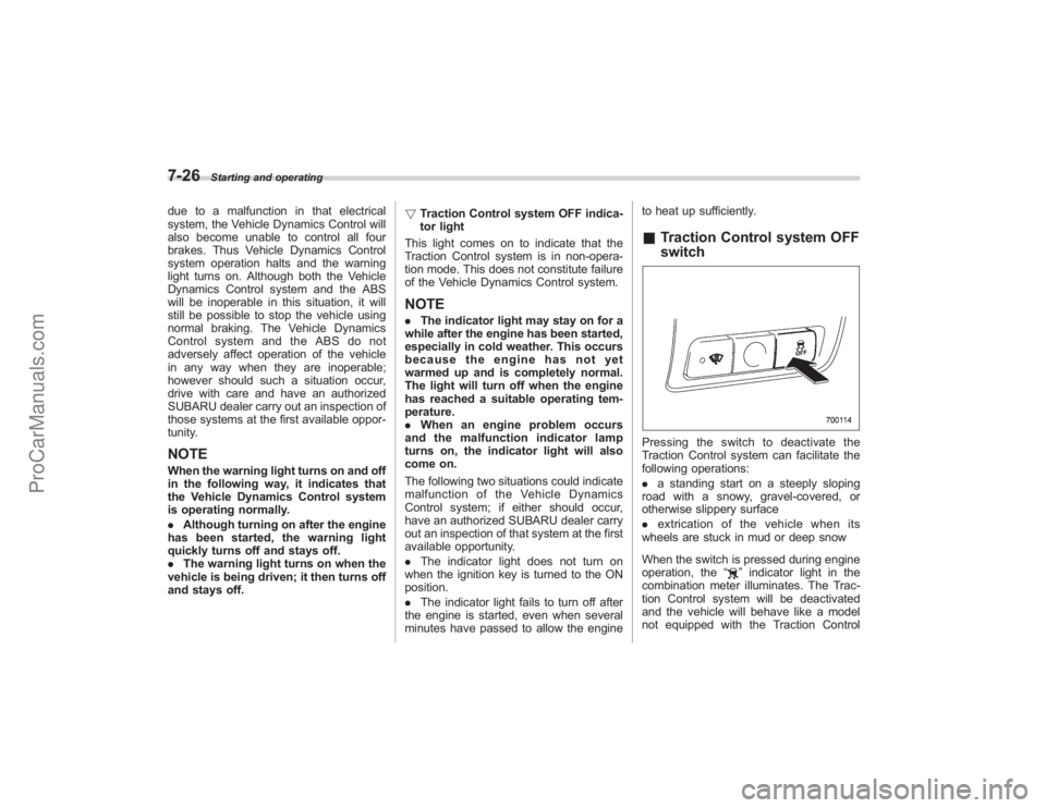
&
Traction Control system OFF
switchPressing the switch to deactivate the
Traction Control system can facilitate the
following operations:
. a standing start on a steeply sloping
road with a snowy, gravel-covered, or
otherwise slippery surface
. extrication of the vehicle when its
wheels are stuck in mud or deep snow
When the switch is pressed during engine
operation, the “
”indicator light in the
combination meter illuminates. The Trac-
tion Control system will be deactivated
and the vehicle will behave like a model
not equipped with the Traction Control
ProCarManuals.com
Page 389 of 409
whitewall, bears white lettering
or bears manufacturer, brand,
and/or model name molding that
is higher or deeper than the
same molding on the other side-
wall of the tire, or(2)
The outward facing sidewall
of an asymmetrical tire that has
a particular side that must al-
ways face outward when mount-
ing on a vehicle.
.
Accessory weight
The combined weight (in excess of
those standard items which may be
replaced) of floor mats, leather
seats and cross bars to the extent
that these items are available as
factory-installed equipment
(whether installed or not)..
Curb weight
The weight of a motor vehicle with
standard equipment including the
maximum capacity of fuel, oil, and
coolant and air conditioning..
Maximum loaded vehicle weight
The sum of curb weight, accessory
weight, vehicle capacity weight and production options weight.
.
Normal occupant weight
150 lbs (68 kg) times the number of
occupants (3 occupants)..
Occupant distribution
Distribution of occupants in a vehi-
cle, 2 in front, 1 in rear seat..
Production options weight
The combined weight of those
installed regular production options
weighing over 5.1 lbs (2.3 kg) in
excess of those standards items
which they replace, not previously
considered in curb weight or acces-
sory weight..
Vehicle capacity weight
The total weight of cargo, luggage
and occupants that can be added to
the vehicle..
Vehicle maximum load on a tire
Load on an individual tire that is
determined by distributing to each
axle its share of the maximum
loaded vehicle weight and dividing
by two..
Vehicle normal load on a tire
Load on an individual tire that isdetermined by distributing to each
axle its share of the curb weight,
accessory weight, and normal oc-
cupant weight and dividing by two.
&
Tire care –maintenance and
safety practices.
Check on a daily basis that the
tires are free from serious damage,
nails, and stones. At the same time,
check the tires for abnormal wear.
.
Inspect the tire tread regularly
and replace the tires before their
tread wear indicators become visi-
ble. When a tire ’s tread wear
indicator becomes visible, the tire
is worn beyond the acceptable limit
and must be replaced immediately.
With a tire in this condition, driving
at even low speeds in wet weather
can cause the vehicle to hydro-
plane. Possible resulting loss of
vehicle control can lead to an
accident.
.
To maximize the life of each tire
and ensure that the tires wear
uniformly, it is best to rotate the
Consumer information and Reporting safety defects
13-7
– CONTINUED –
ProCarManuals.com
Page 403 of 409
Wiper blades....................................................... 11-35
Recommended Automatic transmission fluid .................................. 11-16
Brake fluid. .......................................................... 11-21
OIL grade and viscosity ............. 11-9, 11-10, 11-17, 11-18
Power steering fluid .............................................. 11-20
Spark plugs ......................................................... 11-15
Remote engine start system ......................................... 7-8
Remote keyless entry system ....................................... 2-7
Replacement Brake pad and lining ............................................ 11-22
Wiper blades ....................................................... 11-33
Replacing Air cleaner element .............................................. 11-14
Battery (remote keyless entry system) ....................... 2-7
Lost transmitters (keyless entry system) .................... 2-11
Replacing bulbs ....................................................... 11-41
Backup light/Tail light ............................................ 11-47
Cargo area light ................................................... 11-50
Clearance light .................................................... 11-44
Dome light .......................................................... 11-48
Door step light ..................................................... 11-50
Front fog light ...................................................... 11-45
Front turn signal light ............................................ 11-45
Headlight ............................................................ 11-42
License plate light ................................................ 11-47
Map light ............................................................. 11-49
Rear combination light .......................................... 11-46
Rear gate light ..................................................... 11-47
Vanity mirror light ................................................. 11-49
Rocking the vehicle .................................................... 8-11 Roof rail and crossbar
................................................ 8-13
S
Safety Precautions when driving ............................................. 4
Symbol ...................................................................... 2
Warnings ................................................................... 2
Seat Fabric .................................................................. 10-5
Heater .................................................................... 1-6
Memory function ...................................................... 1-4
Seatbelt. ........................................................................\
4
Maintenance ......................................................... 1-27
Pretensioners ........................................................ 1-27
Safety tips ............................................................ 1-15
Warning light and chime ................................. 1-17, 3-10
Seatbelts .................................................................. 1-15
Security ID plate .......................................................... 2-3
Selector lever ............................................................ 7-13
Position indicator ................................................... 3-20
Shift lock release ....................................................... 7-17
Shock sensors .......................................................... 2-18
Shopping bag hook .................................................... 6-12
Snow tires ................................................................ 8-10
Snowy
and icy roads ................................................... 8-9
Sounding a panic alarm ............................................. 2-10
Spare tire ................................................................... 9-2
Spark plugs ............................................................. 11-15
Specifications ............................................................ 12-2
Speedometer .............................................................. 3-6
SPORT mode indicator light ........................................ 3-20
Index
14-7
ProCarManuals.com