Page 9 of 63

83A-9
MR-372-J84-83A000$252.mif
V8
83A
INSTRUMENT PANEL
Fault finding - Configurations and programming
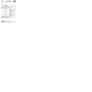
1. CONFIGURATIONS:
WARNING
Run a configuration read to ensure that the new configuration values are used by the system.
LC no. CF no. Configuration Note:
LC001 CF018Reserve capacityAllows the instrument panel to be
configured for switching the indicator
light on.
LC005 CF034 Body type
LC006 CF035Tank capacity
LC007 CF036Key/Card
LC008 CF037 Clock
LC011 CF038 Dimmer present
LC029 CF149 Gearbox typeIf the vehicle has an automatic or sequential
gearbox, check that the instrument panel
shows the gear selected.
If the vehicle is not equipped with an
automatic or sequential gearbox, check that
there is no "Check gearbox" message (this
message indicates the absence of the
automatic gearbox frames if the instrument
panel has been configured for an automatic or
sequential gearbox).
LC030 Vehicle typeValue defined by default: Mégane II
TDB ph2 (EG/MG)
Prog Version: 04xx
Vdiag No.: 08, 0C
MR-372-J84-83A000$252.mif
Page 10 of 63

Prog Version: 04xx
Vdiag No.: 08, 0C
*Miles Per HourLC no. CF no. Configuration")
83A-10
MR-372-J84-83A000$252.mif
V8
INSTRUMENT PANEL
Fault finding - Configurations and programming83A
TDB ph2 (EG/MG)
Prog Version: 04xx
Vdiag No.: 08, 0C
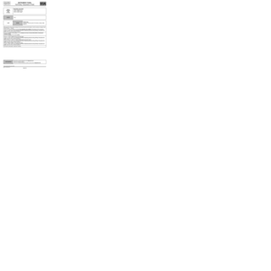
*Miles Per HourLC no. CF no. Configuration Note:
LC049 Type of fuelPetrol: check that the rev counter indicates
7000 rpm as the maximum value.
Diesel: check that the rev counter indicates
6000 rpm as the maximum value and that the
diesel heater plugs “on” indicator light comes
on when the ignition is switched on.
IMPORTANT
it is essential to check this, as it
determines whether the gauges are
operating correctly.
LC051 CF140 Unit of distance
LC052 CF141 Overspeed function - ArabiaWhen driving at speeds greater than
78 mph (130 km/h), the buzzer should sound.
LC054 CF143Unit of measurement for
consumptionLitres/ 100 km (default) - Europe
Miles / gallon - UK
km / l - Brazil
LC056 CF145 Tyre pressure monitorCheck for specific valves.
If the vehicle is equipped with a tyre pressure
monitor: check that the vehicle outline does
not show wheels which are absent and that
there is no “No tyre sensors” message
(message indicating the tyre pressure
monitoring frames are absent).
LC059 CF148 Automatic headlightingCheck for a brightness sensor.
Disconnect the automatic headlights, and
check that the "Auto Headlights Off" message
is displayed.
Page 11 of 63

Prog Version: 04xx
Vdiag No.: 08, 0C
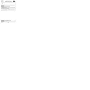
2. PROGRAMMING:
A) Switch on the ignition.")
83A-11
MR-372-J84-83A000$252.mif
V8
INSTRUMENT PANEL
Fault finding - Configurations and programming83A
TDB ph2 (EG/MG)
Prog Version: 04xx
Vdiag No.: 08, 0C
2. PROGRAMMING:
A) Switch on the ignition.
B) Enter the VIN using command VP002 Enter VIN.
C) Program the mileometer using command VP010 Mileometer update.
Check by reading parameter PR009 Mileometer.
D) Enter the oil change frequency in kilometres using command VP006 Oil change frequency in km.
Refer to the information available on the Shared World Information database via RENAULT.NET
(on the maintenance programme page) to check the vehicle configuration.
Ignition on, engine off. Run command VP006 Oil change frequency in KM.
Enter the oil change interval in km.
Example of entry:
Using the CLIP numeric keypad,
enter 20 to display 20,000 km.
or
enter 30 to display 30,000 km.
LC no. CF no. Configuration Note:
LC060 CF002 Language settingCheck the language by using a message.
LC061 CF150 Cruise control/speed limiterIf the vehicle is equipped with a Cruise
Control-Speed Limiter function: check that the
cruise control or speed limiter indicator light
comes on when the cruise control/speed
limiter button is pressed.
LC064 CF158 Seat belt reminder buzzerThis function should only be inhibited on
authorised vehicles.
LC066 CF040 Particle filter
LC090 CF006 Vehicle speed signal systemIf the vehicle is equipped with ESP: check by
pressing the ESP OFF button that the Traction
control deactivated message appears.
If the vehicle is not equipped with ESP: check
that the ESP warning light does not come on
for 3 seconds when the ignition is switched
on.
LC106 CF198O.C.S. (vdiag 08 and program
version 040B and vdiag 0C)Refer to the information available on the
Shared World Information database via
RENAULT.NET (on the maintenance
programme page) to check the vehicle
configuration.
Page 12 of 63

Prog Version: 04xx
Vdiag No.: 08, 0C
Special features for English versions
The")
83A-12
MR-372-J84-83A000$252.mif
V8
INSTRUMENT PANEL
Fault finding - Configurations and programming83A
TDB ph2 (EG/MG)
Prog Version: 04xx
Vdiag No.: 08, 0C
Special features for English versions
The newly supplied instrument panel is configured, by default, in kilometres.
In addition to the language configuration CF002 Language setting, carry out the calculation below to allow
the instrument panel to display consistent values between the distance before next oil change and the
desired oil change frequency.
To display the oil change frequency in miles, multiply the value in miles indicated in the Maintenance
booklet by 10 then divide by 6, to find the exact figure in kilometres.
After the value has been entered, the computer automatically performs the conversion into miles for the
oil service interval.
It is imperative to use the following procedure for correct functioning of the range and oil change
frequency.
Example: 18,000 miles x 10 = 180 000 miles, then divide by 6 = 30,000 km (Enter 30)
Check by reading parameter PR005 Oil change frequency in km.
A) Program the distance to next oil service in kilometres using command VP008 Distance to next oil
service: current value in KM.
Check by reading parameter PR007 Distance to next oil service: current value in KM.
B) Program the oil change frequency in months using command VP007 Oil change frequency in
months.
Check by reading parameter PR006 Oil change frequency in months.
C)Program the oil service interval in months using command VP009 Oil service interval: actual value in
months.
Check by reading parameter PR008 Oil service interval: actual value in months.
D) Program the fuel sender using command VP011 Fuel sender calibration.
There are 2 pieces of information to provide:
–Type of fuel (check by reading configuration LC049).
–Fuel level indicator:
–analogue (needle display),
–digital (bargraph display).
Page 13 of 63
83A-13
MR-372-J84-83A000$315.mif
V8
83A
INSTRUMENT PANEL
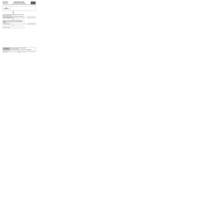
Fault finding - Fault summary table
Tool faultAssociated
DTCDiagnostic tool title
DF007
DF016
DF018
DF0199402
9401
9405
9404Fuel sender circuit
Oil level sensor circuit
Instrument panel
Battery voltage
TDB ph2 (EG/MG)
Prog Version: 04xx
Vdiag No.: 08, 0C
MR-372-J84-83A000$315.mif
Page 14 of 63

83A-14
MR-372-J84-83A000$378.mif
V8
83A
INSTRUMENT PANEL
Fault finding - Interpretation of faults
TDB_V08_DF007/ TDB_V0C_DF007
DF007
PRESENT
OR
STOREDFUEL SENDER CIRCUIT
CO: Open circuit
CC: Short circuit
NOTESConditions for applying the fault finding procedure to stored faults:
The fault is declared present after 60 seconds, with the ignition on.
Special notes:
Check the consistency between the instrument panel display and parameter PR035
Fuel level.
CO
NOTESSpecial note:
The fault is declared present if the fuel sender resistance is
greater than 350 Ω.
Manipulate the wiring harness between the instrument panel and the fuel sender in order to produce a change in
fault status (Present → Stored).
Look for possible damage to the harness, and check the connection and condition of the fuel sender and its
connections.
If there is a repair method (see Technical note 6015A, Repairing electrical wiring, Wiring: Precautions for
repair) repair the wiring, otherwise replace it.
Check the continuity of the following connections:
Fuel sender track 2 track 15, Grey instrument panel connector
Fuel sender track 4 track 2, Grey instrument panel connector
If there is a repair method (see Technical note 6015A, Repairing electrical wiring, Wiring: Precautions for
repair) repair the wiring, otherwise replace it.
Measure the resistance between tracks 4 and 2 of the fuel sender.
Replace the fuel sender if the resistance value is not: 290 Ω fuel tank in reserve
54 Ω fuel tank full
If the fault is still present, contact the Techline.
AFTER REPAIRDeal with any faults declared by the diagnostic tool.
Clear the computer memory.
Carry out a road test followed by another check with the diagnostic tool.
TDB ph2 (EG/MG)
Prog version: 04xx
Vdiag No.: 08, 0C
MR-372-J84-83A000$378.mif
Page 15 of 63

Prog version: 04xx
Vdiag No.: 08, 0C
DF007
CONTINUED
CC
NOTESThe fault is declared pr")
83A-15
MR-372-J84-83A000$378.mif
V8
INSTRUMENT PANEL
Fault finding - Interpretation of faults83A
TDB ph2 (EG/MG)
Prog version: 04xx
Vdiag No.: 08, 0C
DF007
CONTINUED
CC
NOTESThe fault is declared present if the fuel sender resistance is
less than 5 Ω.
Manipulate the wiring harness between the instrument panel and the fuel sender in order to produce a change in
fault status (Present → Stored).
Look for possible damage to the harness, and check the connection and condition of the fuel sender and its
connections.
If there is a repair method (see Technical Note 6015A, Repairing electrical wiring, Wiring: Precautions for
repair), repair the wiring, otherwise replace it.
Disconnect the fuel sender connector and check for a change in fault status.
If the fault remains in short circuit, check the insulation and continuity of the following connections, with the
connector disconnected:
Fuel sender connector track 2 track 15, Grey instrument panel connector
Fuel sender connector track 4 track 2, Grey instrument panel connector
If there is a repair method (see Technical note 6015A, Repairing electrical wiring, Wiring: Precautions for
repair) repair the wiring, otherwise replace it.
If the fault becomes an open circuit fault, move to the next step of the fault finding.
Measure the resistance between tracks 4 and 2 of the fuel sender.
Replace the fuel sender if the resistance value is not: 290 Ω fuel tank in reserve
54 Ω fuel tank full
If the fault is still present, contact the Techline.
AFTER REPAIRDeal with any faults displayed by the diagnostic tool.
Clear the computer memory.
Carry out a road test followed by another check with the diagnostic tool.
Page 16 of 63

Prog version: 04xx
Vdiag No.: 08, 0C
DF016
PRESENT
OIL LEVEL SENSOR CIRCUIT
CO : Open")
83A-16
MR-372-J84-83A000$378.mif
V8
INSTRUMENT PANEL
Fault finding - Interpretation of faults83A
TDB ph2 (EG/MG)
Prog version: 04xx
Vdiag No.: 08, 0C
DF016
PRESENT
OIL LEVEL SENSOR CIRCUIT
CO : Open circuit
CC : Short circuit
1.DEF: Inconsistency
NOTESSpecial notes:
Check the consistency between the instrument panel display and the actual oil level
(top up if incorrect).
CO
1.DEF
NOTESNone.
Look for possible damage to the harness, and check the connection and condition of the oil level sensor and its
connections.
If there is a repair method (see Technical Note 6015A, Repairing electrical wiring, Wiring:
Precautions for repair) repair the wiring, otherwise replace it.
Check the insulation and continuity of the following connections:
Vdiag 44 UPC:
Oil level sensor track 1 track 11, black connector (PEM), Protection
and Switching Unit
Oil level sensor track 2 track 10, black connector (PEM), Protection
and Switching Unit
Instrument panel connection track 10 track 5, black connector (PEH), Protection
and Switching Unit
Instrument panel track 3 track 4, black connector (PEH), Protection
and Switching Unit
UPC Vdiag 48:
Oil level sensor track 1 track 11, connector MT1, Protection and
Switching Unit
Oil level sensor track 2 track 12, connector MT1, Protection and
Switching Unit
Instrument panel connection track 10 track 6, connector CT1, Protection and
Switching Unit
Instrument panel track 3 track 5, connector CT1, Protection and
Switching Unit
If there is a repair method (see Technical note 6015A, Repairing electrical wiring, Wiring: Precautions for
repair) repair the wiring, otherwise replace it.
Measure the resistance between tracks 1 and 2 of the oil level sensor.
Replace the oil level sensor if the resistance is not between 3 and 20 ΩΩ Ω Ω
.
If the fault is still present, contact the Techline.
AFTER REPAIRDeal with any faults declared by the diagnostic tool.
Clear the computer memory.
Carry out a road test followed by another check with the diagnostic tool.
TDB_V08_DF016P /TDB_V0C_DF016P