2008 NISSAN TIIDA stop start
[x] Cancel search: stop startPage 958 of 2771

DTC P0868 SECONDARY PRESSURE DOWN
CVT-119
< SERVICE INFORMATION >
D
E
F
G
H
I
J
K
L
MA
B
CVT
N
O
P
DTC P0868 SECONDARY PRESSURE DOWN
DescriptionINFOID:0000000001703593
• The pressure control solenoid valve B (secondary pressure solenoid valve) is included in the control valve
assembly.
• The pressure control solenoid valve B (secondary pressure solenoid valve) regulates the secondary pres-
sure to suit the driving condition in response to a signal sent from the TCM.
CONSULT-III Reference Value in Data Monitor ModeINFOID:0000000001703594
Remarks: Specification data are reference values.
On Board Diagnosis LogicINFOID:0000000001703595
• This is not an OBD-II self-diagnostic item.
• Diagnostic trouble code “P0868 SEC/PRESS DOWN” with CONSULT-III is detected when secondary fluid
pressure is too low compared with the commanded value while driving.
Possible CauseINFOID:0000000001703596
• Harness or connectors
(Solenoid circuit is open or shorted.)
• Pressure control solenoid valve B (Secondary pressure solenoid valve) system
• Transmission fluid pressure sensor A (Secondary pressure sensor)
• Line pressure control system
DTC Confirmation ProcedureINFOID:0000000001703597
CAUTION:
Always drive vehicle at a safe speed.
NOTE:
If “DTC Confirmation Procedure” has been previously performed, always turn ignition switch OFF and
wait at least 10 seconds before performing the next test.
After the repair, perform the following procedure to confirm the malfunction is eliminated.
WITH CONSULT-III
1. Turn ignition switch ON and select “DATA MONITOR” mode for “TRANSMISSION” with CONSULT-III.
2. Make sure that output voltage of CVT fluid temperature sensor is within the range below.
ATF TEMP SEN: 1.0 - 2.0 V
If out of range, drive the vehicle to decrease the voltage (warm up the fluid) or stop engine to
increase the voltage (cool down the fluid)
3. Start engine and maintain the following conditions for at least 10 consecutive seconds.
VEHICLE SPEED (accelerate slowly): 0 → 50 km/h (31 MPH)
ACC PEDAL OPEN: 0.5/8 - 1.0/8
RANGE: “D” position
4. If DTC is detected, go to CVT-119, "
Diagnosis Procedure".
Diagnosis ProcedureINFOID:0000000001703598
1.CHECK INPUT SIGNAL
With CONSULT-III
1. Start engine.
2. Select “MAIN SIGNALS” in “DATA MONITOR” mode for “TRANSMISSION” with CONSULT-III.
3. Start vehicle and read out the value of “SEC PRESS”.
Item name Condition Display value (Approx.)
SEC PRESS “N” position idle 0.8 MPa
Item name Condition Display value (Approx.)
SEC PRESS “N” position idle 0.8 MPa
Page 960 of 2771
DTC P1701 TRANSMISSION CONTROL MODULE (POWER SUPPLY)
CVT-121
< SERVICE INFORMATION >
D
E
F
G
H
I
J
K
L
MA
B
CVT
N
O
P
DTC P1701 TRANSMISSION CONTROL MODULE (POWER SUPPLY)
DescriptionINFOID:0000000001703599
When the power supply to the TCM is cut OFF, for example because the battery is removed, and the self-diag-
nosis memory function stops, malfunction is detected.
NOTE:
Since “P1701 TCM-POWER SUPPLY” will be indicated when replacing TCM, perform diagnosis after
erasing “SELF-DIAG RESULTS”
On Board Diagnosis LogicINFOID:0000000001703600
• This is not an OBD-II self-diagnostic item.
• Diagnostic trouble code “P1701 TCM-POWER SUPPLY” with CONSULT-III is detected when TCM does not
receive the voltage signal from the battery power supply.
• This is not a malfunction message. (Whenever shutting OFF a power supply to the TCM, this message
appears on the screen.)
Possible CauseINFOID:0000000001703601
Harness or connectors
(Battery or ignition switch and TCM circuit is open or shorted.)
DTC Confirmation ProcedureINFOID:0000000001703602
NOTE:
If “DTC Confirmation Procedure” has been previously conducted, always turn ignition switch OFF and
wait at least 10 seconds before conducting the next test.
After the repair, perform the following procedure to confirm the malfunction is eliminated.
WITH CONSULT-III
1. Turn ignition switch ON. (Do not start engine.)
2. Select “DATA MONITOR” mode for “TRANSMISSION” with CONSULT-III.
3. Wait for at least 2 consecutive seconds.
4. If DTC is detected, go to CVT-123, "
Diagnosis Procedure" .
Page 975 of 2771
CVT-136
< SERVICE INFORMATION >
DTC P1745 LINE PRESSURE CONTROL
DTC P1745 LINE PRESSURE CONTROL
DescriptionINFOID:0000000001703635
The pressure control solenoid valve A (line pressure solenoid valve) regulates the oil pump discharge pres-
sure to suit the driving condition in response to a signal sent from the TCM.
On Board Diagnosis LogicINFOID:0000000001703636
• This is not an OBD-II self-diagnostic item.
• Diagnostic trouble code “P1745 L/PRESS CONTROL” with CONSULT-III is detected when TCM detects the
unexpected line pressure.
Possible CauseINFOID:0000000001703637
TCM
DTC Confirmation ProcedureINFOID:0000000001703638
NOTE:
If “DTC Confirmation Procedure” has been previously performed, always turn ignition switch OFF and
wait at least 10 seconds before performing the next test.
After the repair, touch “ERASE” on “SELF-DIAG RESULTS” and then perform the following procedure to con-
firm the malfunction is eliminated.
WITH CONSULT-III
1. Turn ignition switch ON and select “DATA MONITOR” mode for “TRANSMISSION” with CONSULT-III.
2. Make sure that output voltage of CVT fluid temperature sensor is within the range below.
ATF TEMP SEN: 1.0 - 2.0 V
If out of range, drive the vehicle to decrease the voltage (warm up the fluid) or stop engine to
increase the voltage (cool down the fluid)
3. If DTC is detected, go to CVT-136, "
Diagnosis Procedure" .
Diagnosis ProcedureINFOID:0000000001703639
1.CHECK DTC
1. Turn ignition switch ON. (Do not start engine.)
2. Select “SELF-DIAG RESULTS” mode for “TRANSMISSION” with CONSULT-III.
3. Erase self-diagnostic results. Refer to CVT-26, "
OBD-II Diagnostic Trouble Code (DTC)".
4. Turn ignition switch OFF, and wait for 10 seconds or more.
5. Start engine.
6. Confirm self-diagnostic results again. Refer to CVT-47, "
CONSULT-III Function (TRANSMISSION)" .
Is the
“P1745 L/PRESS CONTROL” displayed?
YES >> Replace TCM. Refer to CVT-8, "Service After Replacing TCM and Transaxle Assembly" .
NO >>INSPECTION END
Page 980 of 2771

DTC P1778 STEP MOTOR - FUNCTION
CVT-141
< SERVICE INFORMATION >
D
E
F
G
H
I
J
K
L
MA
B
CVT
N
O
P
DTC P1778 STEP MOTOR - FUNCTION
DescriptionINFOID:0000000001703648
• The step motor is included in the control valve assembly.
• The step motor's 4 aspects of ON/OFF change according to the signal from TCM. As a result, the flow of line
pressure to primary pulley is changed and pulley ratio is controlled.
• This diagnosis item is detected when electrical system is OK, but mechanical system is NG.
• This diagnosis item is detected when the state of the changing the speed mechanism in unit does not oper-
ate normally.
CONSULT-III Reference Value in Data Monitor ModeINFOID:0000000001703649
Remarks: Specification data are reference values.
On Board Diagnosis LogicINFOID:0000000001703650
• This is an OBD-II self-diagnostic item.
• Diagnostic trouble code “P1778 STEP MOTR/FNC” with CONSULT-III is detected under the following condi-
tions.
- When not changing the pulley ratio according to the instruction of TCM.
Possible CauseINFOID:0000000001703651
Step motor
DTC Confirmation ProcedureINFOID:0000000001703652
CAUTION:
• Always drive vehicle at a safe speed.
• Before starting “DTC Confirmation Procedure”, confirm “Hi” or “Mid” or “Low” fixation by “PRI
SPEED” and “VEHICLE SPEED” on “DATA MONITOR MODE”.
• If hi-geared fixation occurred, go to CVT-142, "
Diagnosis Procedure".
NOTE:
If “DTC Confirmation Procedure” has been previously performed, always turn ignition switch OFF and
wait at least 10 seconds before performing the next test.
After the repair, touch “ERASE” on “SELF-DIAG RESULTS” and then perform the following procedure to con-
firm the malfunction is eliminated.
WITH CONSULT-III
1. Turn ignition switch ON and select “DATA MONITOR” mode for “TRANSMISSION” with CONSULT-III.
2. Make sure that output voltage of CVT fluid temperature sensor is within the range below.
ATF TEMP SEN: 1.0 - 2.0 V
If out of range, drive the vehicle to decrease the voltage (warm up the fluid) or stop engine to
increase the voltage (cool down the fluid)
3. Select “DATA MONITOR” mode for “TRANSMISSION” with CONSULT-III.
4. Start engine and maintain the following conditions for at least 30 consecutive seconds.
TEST START FROM 0 km/h (0 MPH)
CONSTANT ACCELERATION: Keep 30 sec or more
VEHICLE SPEED: 10 km/h (6 MPH) or more
ACC PEDAL OPEN: More than 1.0/8
RANGE: “D” position
ENG SPEED: 450 rpm or more
5. If DTC is detected, go to CVT-142, "
Diagnosis Procedure".
WITH GST
Follow the procedure “WITH CONSULT-III”.
Item name Condition Display value (Approx.)
STM STEP
During driving−20 step - 180 step
GEAR RATIO2.56 - 0.43
Page 1010 of 2771
SHIFT CONTROL SYSTEM
CVT-171
< SERVICE INFORMATION >
D
E
F
G
H
I
J
K
L
MA
B
CVT
N
O
P
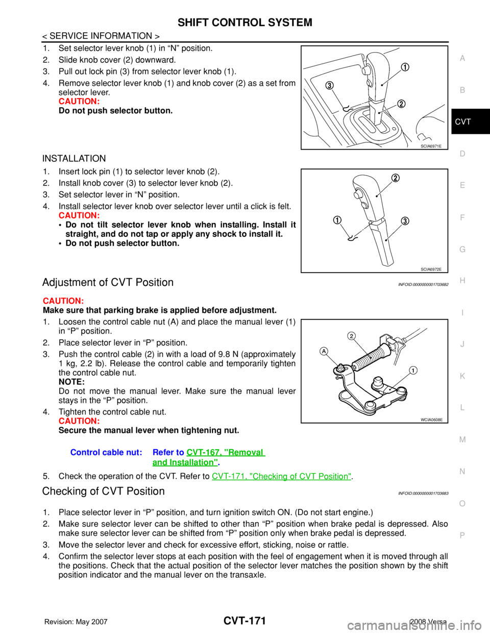
1. Set selector lever knob (1) in “N” position.
2. Slide knob cover (2) downward.
3. Pull out lock pin (3) from selector lever knob (1).
4. Remove selector lever knob (1) and knob cover (2) as a set from
selector lever.
CAUTION:
Do not push selector button.
INSTALLATION
1. Insert lock pin (1) to selector lever knob (2).
2. Install knob cover (3) to selector lever knob (2).
3. Set selector lever in “N” position.
4. Install selector lever knob over selector lever until a click is felt.
CAUTION:
• Do not tilt selector lever knob when installing. Install it
straight, and do not tap or apply any shock to install it.
• Do not push selector button.
Adjustment of CVT PositionINFOID:0000000001703682
CAUTION:
Make sure that parking brake is applied before adjustment.
1. Loosen the control cable nut (A) and place the manual lever (1)
in “P” position.
2. Place selector lever in “P” position.
3. Push the control cable (2) in with a load of 9.8 N (approximately
1 kg, 2.2 lb). Release the control cable and temporarily tighten
the control cable nut.
NOTE:
Do not move the manual lever. Make sure the manual lever
stays in the “P” position.
4. Tighten the control cable nut.
CAUTION:
Secure the manual lever when tightening nut.
5. Check the operation of the CVT. Refer to CVT-171, "
Checking of CVT Position".
Checking of CVT PositionINFOID:0000000001703683
1. Place selector lever in “P” position, and turn ignition switch ON. (Do not start engine.)
2. Make sure selector lever can be shifted to other than “P” position when brake pedal is depressed. Also
make sure selector lever can be shifted from “P” position only when brake pedal is depressed.
3. Move the selector lever and check for excessive effort, sticking, noise or rattle.
4. Confirm the selector lever stops at each position with the feel of engagement when it is moved through all
the positions. Check that the actual position of the selector lever matches the position shown by the shift
position indicator and the manual lever on the transaxle.
SCIA6971E
SCIA6972E
Control cable nut: Refer to CVT-167, "Removal
and Installation".
WCIA0608E
Page 1032 of 2771
COMBINATION METERS
DI-11
< SERVICE INFORMATION >
C
D
E
F
G
H
I
J
L
MA
B
DI
N
O
P
Self-Diagnosis Mode of Combination MeterINFOID:0000000001704497
SELF-DIAGNOSIS MODE FUNCTION
• Self-diagnosis can check for continuity between meter control circuit and each meter (speedometer, tachom-
eter and fuel gauge).
• Self-diagnosis can check for odo/trip meter and A/T indicator (with A/T) or CVT indicator (with CVT) seg-
ment, low-fuel level warning lamp, low water temperature indicator lamp, and high water temperature warn-
ing lamp.
OPERATION PROCEDURE
1. Turn the ignition switch ON, and switch the odo/trip meter to “trip A” or “trip B”.
NOTE:
13 B Illumination control switch (-) — — Refer to LT- 1 0 5 , "System Description" .
17 GWasher fluid level switch
(Canada models)ONWasher fluid level low 0
Washer fluid level normal Battery voltage
21
BGround — — 0 22
23
24 V Fuel level sensor ground (-) ON — 0
26 BVehicle speed sensor ground
(without ABS or CVT)ON — 0
27 G Battery power supply OFF — Battery voltage
28 SB Ignition switch ON or START ON — Battery voltage
29 GR Seat belt buckle switch RH ONUnfastened (ON) 0
Fastened (OFF) Battery voltage
30 G Stop lamp switch ONBrake pedal depressed Battery voltage
Brake pedal released 0
31 V A/T N-range input (with A/T) ONTransmission gear selector lever
in N positionBattery voltage
Transmission gear selector lever
other than N position0
32 W A/T P-range input (with A/T) ONTransmission gear selector lever
in P positionBattery voltage
Transmission gear selector lever
other than P position0
33 Y A/T PN output (with A/T) ONTransmission gear selector lever
in P or N position0
Transmission gear selector lever
other than P or N positionBattery voltage
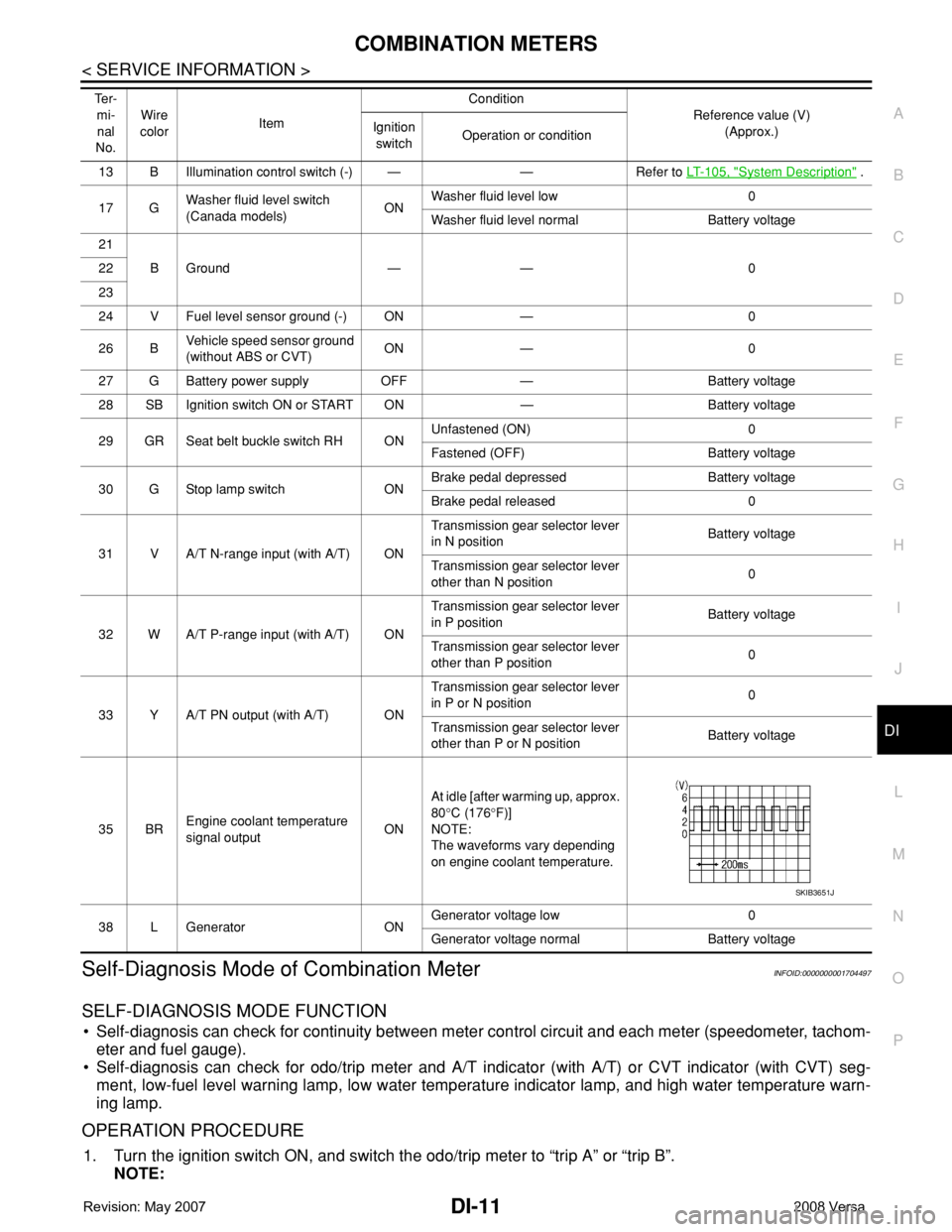
35 BREngine coolant temperature
signal outputONAt idle [after warming up, approx.
80°C (176°F)]
NOTE:
The waveforms vary depending
on engine coolant temperature.
38 L Generator ONGenerator voltage low 0
Generator voltage normal Battery voltage Te r -
mi-
nal
No.Wire
colorItemCondition
Reference value (V)
(Approx.) Ignition
switchOperation or condition
SKIB3651J
Page 1098 of 2771
EC-24
< SERVICE INFORMATION >
ENGINE CONTROL SYSTEM
fuel ratio (A/F) sensor 1 in the exhaust manifold to monitor whether the engine operation is rich or lean. The
ECM adjusts the injection pulse width according to the sensor voltage signal. For more information about air
fuel ratio (A/F) sensor 1, refer to EC-213
. This maintains the mixture ratio within the range of stoichiometric
(ideal air/fuel mixture).
This stage is referred to as the closed loop control condition.
Heated oxygen sensor 2 is located downstream of the three way catalyst (manifold). Even if the switching
characteristics of air fuel ratio (A/F) sensor 1 shift, the air/fuel ratio is controlled to stoichiometric by the signal
from heated oxygen sensor 2.
Open Loop Control
The open loop system condition refers to when the ECM detects any of the following conditions. Feedback
control stops in order to maintain stabilized fuel combustion.
• Deceleration and acceleration
• High-load, high-speed operation
• Malfunction of air fuel ratio (A/F) sensor 1 or its circuit
• Insufficient activation of air fuel ratio (A/F) sensor 1 at low engine coolant temperature
• High engine coolant temperature
• During warm-up
• After shifting from N to D (A/T and CVT models)
• When starting the engine
MIXTURE RATIO SELF-LEARNING CONTROL
The mixture ratio feedback control system monitors the mixture ratio signal transmitted from air fuel ratio (A/F)
sensor 1. This feedback signal is then sent to the ECM. The ECM controls the basic mixture ratio as close to
the theoretical mixture ratio as possible. However, the basic mixture ratio is not necessarily controlled as orig-
inally designed. Both manufacturing differences (i.e., mass air flow sensor hot wire) and characteristic
changes during operation (i.e., fuel injector clogging) directly affect mixture ratio.
Accordingly, the difference between the basic and theoretical mixture ratios is monitored in this system. This is
then computed in terms of “injection pulse duration” to automatically compensate for the difference between
the two ratios.
“Fuel trim” refers to the feedback compensation value compared against the basic injection duration. Fuel trim
includes short term fuel trim and long term fuel trim.
“Short term fuel trim” is the short-term fuel compensation used to maintain the mixture ratio at its theoretical
value. The signal from air fuel ratio (A/F) sensor 1 indicates whether the mixture ratio is RICH or LEAN com-
pared to the theoretical value. The signal then triggers a reduction in fuel volume if the mixture ratio is rich, and
an increase in fuel volume if it is lean.
“Long term fuel trim” is overall fuel compensation carried out long-term to compensate for continual deviation
of the short term fuel trim from the central value. Such deviation will occur due to individual engine differences,
wear over time and changes in the usage environment.
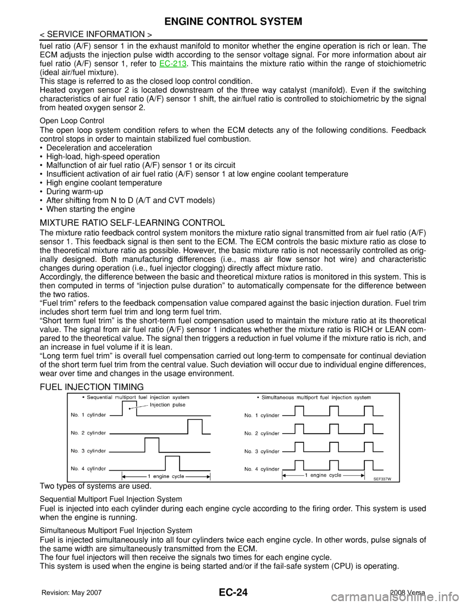
FUEL INJECTION TIMING
Two types of systems are used.
Sequential Multiport Fuel Injection System
Fuel is injected into each cylinder during each engine cycle according to the firing order. This system is used
when the engine is running.
Simultaneous Multiport Fuel Injection System
Fuel is injected simultaneously into all four cylinders twice each engine cycle. In other words, pulse signals of
the same width are simultaneously transmitted from the ECM.
The four fuel injectors will then receive the signals two times for each engine cycle.
This system is used when the engine is being started and/or if the fail-safe system (CPU) is operating.
SEF337W
Page 1135 of 2771
ON BOARD DIAGNOSTIC (OBD) SYSTEM
EC-61
< SERVICE INFORMATION >
C
D
E
F
G
H
I
J
K
L
MA
EC
N
P O
When there is an open circuit on MIL circuit, the ECM cannot warn the driver by MIL lighting up when there is
malfunction on engine control system.
Therefore, when electrical controlled throttle and part of ECM related diagnoses are continuously detected as
NG for 5 trips, ECM warns the driver that engine control system malfunctions and MIL circuit is open by means
of operating fail-safe function.
The fail-safe function also operates when above diagnoses except MIL circuit are detected, and demands the
driver to repair the malfunction.
MIL Flashing Without DTC
When any SRT codes are not set, MIL may flash without DTC. For the details, refer to EC-47, "Emission-
related Diagnostic Information".
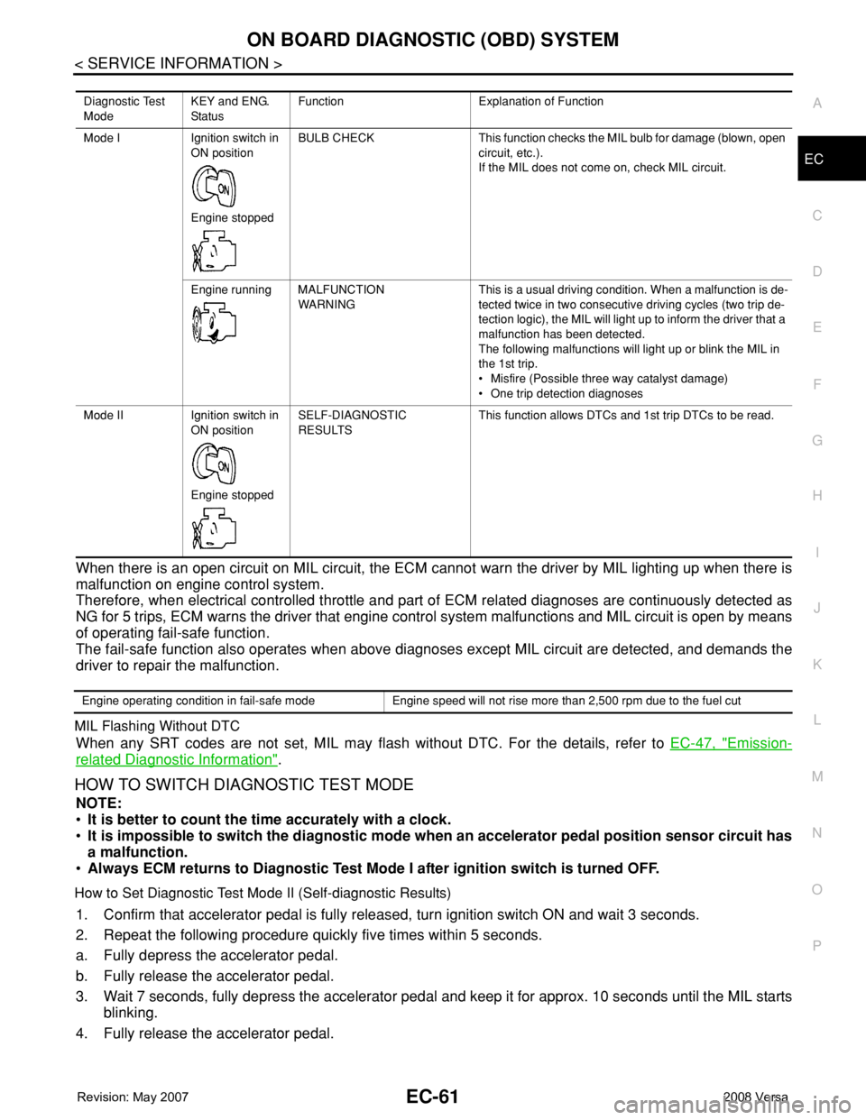
HOW TO SWITCH DIAGNOSTIC TEST MODE
NOTE:
•It is better to count the time accurately with a clock.
•It is impossible to switch the diagnostic mode when an accelerator pedal position sensor circuit has
a malfunction.
•Always ECM returns to Diagnostic Test Mode I after ignition switch is turned OFF.
How to Set Diagnostic Test Mode II (Self-diagnostic Results)
1. Confirm that accelerator pedal is fully released, turn ignition switch ON and wait 3 seconds.
2. Repeat the following procedure quickly five times within 5 seconds.
a. Fully depress the accelerator pedal.
b. Fully release the accelerator pedal.
3. Wait 7 seconds, fully depress the accelerator pedal and keep it for approx. 10 seconds until the MIL starts
blinking.
4. Fully release the accelerator pedal.
Diagnostic Test
ModeKEY and ENG.
Sta tusFunction Explanation of Function
Mode I Ignition switch in
ON position
Engine stoppedBULB CHECK This function checks the MIL bulb for damage (blown, open
circuit, etc.).
If the MIL does not come on, check MIL circuit.
Engine running MALFUNCTION
WARNINGThis is a usual driving condition. When a malfunction is de-
tected twice in two consecutive driving cycles (two trip de-
tection logic), the MIL will light up to inform the driver that a
malfunction has been detected.
The following malfunctions will light up or blink the MIL in
the 1st trip.
• Misfire (Possible three way catalyst damage)
• One trip detection diagnoses
Mode II Ignition switch in
ON position
Engine stoppedSELF-DIAGNOSTIC
RESULTSThis function allows DTCs and 1st trip DTCs to be read.
Engine operating condition in fail-safe mode Engine speed will not rise more than 2,500 rpm due to the fuel cut