2008 NISSAN TIIDA stop start
[x] Cancel search: stop startPage 1145 of 2771

BASIC SERVICE PROCEDURE
EC-71
< SERVICE INFORMATION >
C
D
E
F
G
H
I
J
K
L
MA
EC
N
P O
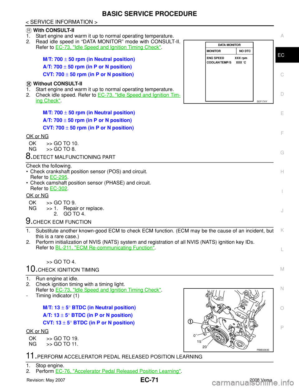
With CONSULT-II
1. Start engine and warm it up to normal operating temperature.
2. Read idle speed in “DATA MONITOR” mode with CONSULT-II.
Refer to EC-73, "
Idle Speed and Ignition Timing Check".
Without CONSULT-II
1. Start engine and warm it up to normal operating temperature.
2. Check idle speed. Refer to EC-73, "
Idle Speed and Ignition Tim-
ing Check".
OK or NG
OK >> GO TO 10.
NG >> GO TO 8.
8.DETECT MALFUNCTIONING PART
Check the following.
• Check crankshaft position sensor (POS) and circuit.
Refer to EC-295
.
• Check camshaft position sensor (PHASE) and circuit.
Refer to EC-302
.
OK or NG
OK >> GO TO 9.
NG >> 1. Repair or replace.
2. GO TO 4.
9.CHECK ECM FUNCTION
1. Substitute another known-good ECM to check ECM function. (ECM may be the cause of an incident, but
this is a rare case.)
2. Perform initialization of NVIS (NATS) system and registration of all NVIS (NATS) ignition key IDs.
Refer to BL-211, "
ECM Re-communicating Function".
>> GO TO 4.
10.CHECK IGNITION TIMING
1. Run engine at idle.
2. Check ignition timing with a timing light.
Refer to EC-73, "
Idle Speed and Ignition Timing Check".
- Timing indicator (1)
OK or NG
OK >> GO TO 19.
NG >> GO TO 11.
11 .PERFORM ACCELERATOR PEDAL RELEASED POSITION LEARNING
1. Stop engine.
2. Perform EC-76, "
Accelerator Pedal Released Position Learning". M/T: 700 ± 50 rpm (in Neutral position)
A/T: 700 ± 50 rpm (in P or N position)
CVT: 700 ± 50 rpm (in P or N position)
M/T: 700 ± 50 rpm (in Neutral position)
A/T: 700 ± 50 rpm (in P or N position)
CVT: 700 ± 50 rpm (in P or N position)
SEF174Y
M/T: 13 ± 5° BTDC (in Neutral position)
A/T: 13 ± 5° BTDC (in P or N position)
CVT: 13 ± 5° BTDC (in P or N position)
PBIB3263E
Page 1150 of 2771

EC-76
< SERVICE INFORMATION >
BASIC SERVICE PROCEDURE
Accelerator Pedal Released Position Learning
INFOID:0000000001702582
DESCRIPTION
Accelerator Pedal Released Position Learning is an operation to learn the fully released position of the accel-
erator pedal by monitoring the accelerator pedal position sensor output signal. It must be performed each time
harness connector of accelerator pedal position sensor or ECM is disconnected.
OPERATION PROCEDURE
1. Make sure that accelerator pedal is fully released.
2. Turn ignition switch ON and wait at least 2 seconds.
3. Turn ignition switch OFF and wait at least 10 seconds.
4. Turn ignition switch ON and wait at least 2 seconds.
5. Turn ignition switch OFF and wait at least 10 seconds.
Throttle Valve Closed Position LearningINFOID:0000000001702583
DESCRIPTION
Throttle Valve Closed Position Learning is an operation to learn the fully closed position of the throttle valve by
monitoring the throttle position sensor output signal. It must be performed each time harness connector of
electric throttle control actuator or ECM is disconnected.
OPERATION PROCEDURE
1. Make sure that accelerator pedal is fully released.
2. Turn ignition switch ON.
3. Turn ignition switch OFF and wait at least 10 seconds.
Make sure that throttle valve moves during above 10 seconds by confirming the operating sound.
Idle Air Volume LearningINFOID:0000000001702584
DESCRIPTION
Idle Air Volume Learning is an operation to learn the idle air volume that keeps each engine within the specific
range. It must be performed under any of the following conditions:
• Each time electric throttle control actuator or ECM is replaced.
• Idle speed or ignition timing is out of specification.
PREPARATION
Before performing Idle Air Volume Learning, make sure that all of the following conditions are satisfied.
Learning will be cancelled if any of the following conditions are missed for even a moment.
• Battery voltage: More than 12.9V (At idle)
• Engine coolant temperature: 70 - 95°C (158 - 203°F)
• Park/neutral position (PNP) switch: ON
• Electric load switch: OFF
[Air conditioner, headlamp, rear window defogger]
On vehicles equipped with daytime light systems, if the parking brake is applied before the engine is
started the headlamp will not be illuminated.
• Steering wheel: Neutral (Straight-ahead position)
• Vehicle speed: Stopped
• Transmission: Warmed-up
- Models with CONSULT-II (A/T and CVT models)
• Drive vehicle until “FLUID TEMP SE” in “DATA MONITOR” mode of “A/T” or “CVT” system indicates less
than 0.9V.
- Models without CONSULT-II (A/T and CVT models) and M/T models
• Drive vehicle for 10 minutes.
OPERATION PROCEDURE
With CONSULT-II
1. Perform EC-76, "Accelerator Pedal Released Position Learning".
2. Perform EC-76, "
Throttle Valve Closed Position Learning".
Page 1152 of 2771

EC-78
< SERVICE INFORMATION >
BASIC SERVICE PROCEDURE
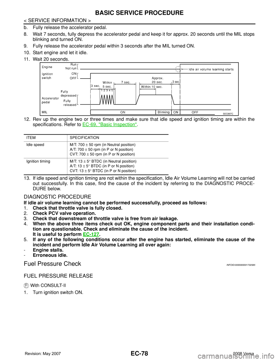
b. Fully release the accelerator pedal.
8. Wait 7 seconds, fully depress the accelerator pedal and keep it for approx. 20 seconds until the MIL stops
blinking and turned ON.
9. Fully release the accelerator pedal within 3 seconds after the MIL turned ON.
10. Start engine and let it idle.
11. Wait 20 seconds.
12. Rev up the engine two or three times and make sure that idle speed and ignition timing are within the
specifications. Refer to EC-69, "
Basic Inspection".
13. If idle speed and ignition timing are not within the specification, Idle Air Volume Learning will not be carried
out successfully. In this case, find the cause of the incident by referring to the DIAGNOSTIC PROCE-
DURE below.
DIAGNOSTIC PROCEDURE
If idle air volume learning cannot be performed successfully, proceed as follows:
1.Check that throttle valve is fully closed.
2.Check PCV valve operation.
3.Check that downstream of throttle valve is free from air leakage.
4.When the above three items check out OK, engine component parts and their installation condi-
tion are questionable. Check and eliminate the cause of the incident.
It is useful to perform EC-127
.
5.If any of the following conditions occur after the engine has started, eliminate the cause of the
incident and perform Idle Air Volume Learning all over again:
-Engine stalls.
-Erroneous idle.
Fuel Pressure CheckINFOID:0000000001702585
FUEL PRESSURE RELEASE
With CONSULT-II
1. Turn ignition switch ON.
ITEM SPECIFICATION
Idle speed M/T: 700 ± 50 rpm (in Neutral position)
A/T: 700 ± 50 rpm (in P or N position)
CVT: 700 ± 50 rpm (in P or N position)
Ignition timing M/T: 13 ± 5° BTDC (in Neutral position)
A/T: 13 ± 5° BTDC (in P or N position)
CVT: 13 ± 5° BTDC (in P or N position)
SEC897C
Page 1162 of 2771

EC-88
< SERVICE INFORMATION >
TROUBLE DIAGNOSIS
• When there is an open circuit on MIL circuit, the ECM cannot warn the driver by lighting up MIL when there
is malfunction on engine control system.
Therefore, when electrical controlled throttle and part of ECM related diagnoses are continuously detected
as NG for 5 trips, ECM warns the driver that engine control system malfunctions and MIL circuit is open by
means of operating fail-safe function.
The fail-safe function also operates when above diagnoses except MIL circuit are detected and demands the
driver to repair the malfunction.
Symptom Matrix ChartINFOID:0000000001702589
SYSTEM — BASIC ENGINE CONTROL SYSTEM
P0117
P0118Engine coolant temperature
sensor circuitEngine coolant temperature will be determined by ECM based on the time after turning
ignition switch ON or START.
CONSULT-II displays the engine coolant temperature decided by ECM.
ConditionEngine coolant temperature decided
(CONSULT-II display)
Just as ignition switch is turned ON
or START40°C (104°F)
More than approx. 4 minutes after
ignition ON or START80°C (176°F)
Except as shown above40 - 80°C (104 - 176°F)
(Depends on the time)
When the fail-safe system for engine coolant temperature sensor is activated, the cool-
ing fan operates while engine is running.
P0122
P0123
P0222
P0223
P2135Throttle position sensor The ECM controls the electric throttle control actuator in regulating the throttle opening
in order for the idle position to be within +10 degrees.
The ECM regulates the opening speed of the throttle valve to be slower than the normal
condition.
So, the acceleration will be poor.
P0643 Sensor power supply ECM stops the electric throttle control actuator control, throttle valve is maintained at a
fixed opening (approx. 5 degrees) by the return spring.
P2100
P2103Throttle control relay ECM stops the electric throttle control actuator control, throttle valve is maintained at a
fixed opening (approx. 5 degrees) by the return spring.
P2101 Electric throttle control func-
tionECM stops the electric throttle control actuator control, throttle valve is maintained at a
fixed opening (approx. 5 degrees) by the return spring.
P2118 Throttle control motor ECM stops the electric throttle control actuator control, throttle valve is maintained at a
fixed opening (approx. 5 degrees) by the return spring.
P2119 Electric throttle control actu-
ator(When electric throttle control actuator does not function properly due to the return
spring malfunction:)
ECM controls the electric throttle actuator by regulating the throttle opening around the
idle position. The engine speed will not rise more than 2,000 rpm.
(When throttle valve opening angle in fail-safe mode is not in specified range:)
ECM controls the electric throttle control actuator by regulating the throttle opening to
20 degrees or less.
(When ECM detects the throttle valve is stuck open:)
While the vehicle is driving, it slows down gradually by fuel cut. After the vehicle stops,
the engine stalls.
The engine can restart in N or P (A/T, CVT), Neutral (M/T) position, and engine speed
will not exceed 1,000 rpm or more.
P2122
P2123
P2127
P2128
P2138Accelerator pedal position
sensorThe ECM controls the electric throttle control actuator in regulating the throttle opening
in order for the idle position to be within +10 degrees.
The ECM regulates the opening speed of the throttle valve to be slower than the normal
condition.
So, the acceleration will be poor. DTC No. Detected items Engine operating condition in fail-safe mode
Engine operating condition in fail-safe mode Engine speed will not rise more than 2,500 rpm due to the fuel cut
Page 1176 of 2771

EC-102
< SERVICE INFORMATION >
TROUBLE DIAGNOSIS
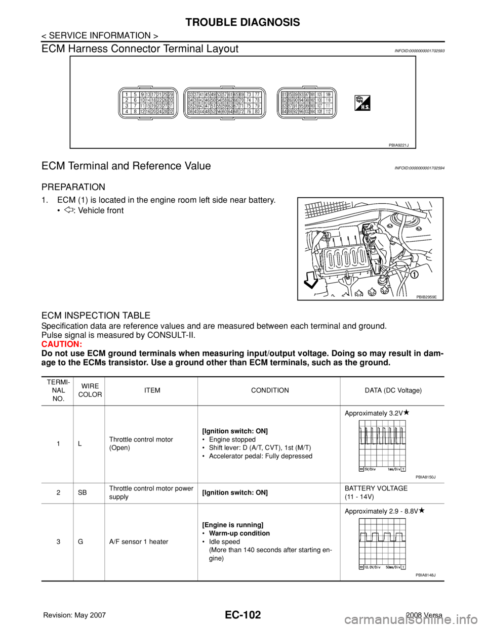
ECM Harness Connector Terminal Layout
INFOID:0000000001702593
ECM Terminal and Reference ValueINFOID:0000000001702594
PREPARATION
1. ECM (1) is located in the engine room left side near battery.
• : Vehicle front
ECM INSPECTION TABLE
Specification data are reference values and are measured between each terminal and ground.
Pulse signal is measured by CONSULT-II.
CAUTION:
Do not use ECM ground terminals when measuring input/output voltage. Doing so may result in dam-
age to the ECMs transistor. Use a ground other than ECM terminals, such as the ground.
PBIA9221J
PBIB2959E
TERMI-
NAL
NO.WIRE
COLORITEM CONDITION DATA (DC Voltage)
1LThrottle control motor
(Open)[Ignition switch: ON]
• Engine stopped
• Shift lever: D (A/T, CVT), 1st (M/T)
• Accelerator pedal: Fully depressedApproximately 3.2V
2SBThrottle control motor power
supply[Ignition switch: ON]BATTERY VOLTAGE
(11 - 14V)
3 G A/F sensor 1 heater[Engine is running]
•Warm-up condition
• Idle speed
(More than 140 seconds after starting en-
gine)Approximately 2.9 - 8.8V
PBIA8150J
PBIA8148J
Page 1177 of 2771
![NISSAN TIIDA 2008 Service Repair Manual TROUBLE DIAGNOSIS
EC-103
< SERVICE INFORMATION >
C
D
E
F
G
H
I
J
K
L
MA
EC
N
P O
4 P Throttle control motor (Close)[Ignition switch: ON]
• Engine stopped
• Shift lever: D (A/T, CVT), 1st (M/T)
• NISSAN TIIDA 2008 Service Repair Manual TROUBLE DIAGNOSIS
EC-103
< SERVICE INFORMATION >
C
D
E
F
G
H
I
J
K
L
MA
EC
N
P O
4 P Throttle control motor (Close)[Ignition switch: ON]
• Engine stopped
• Shift lever: D (A/T, CVT), 1st (M/T)
•](/manual-img/5/57399/w960_57399-1176.png)
TROUBLE DIAGNOSIS
EC-103
< SERVICE INFORMATION >
C
D
E
F
G
H
I
J
K
L
MA
EC
N
P O
4 P Throttle control motor (Close)[Ignition switch: ON]
• Engine stopped
• Shift lever: D (A/T, CVT), 1st (M/T)
• Accelerator pedal: Fully releasedApproximately 1.8V
5GHeated oxygen sensor 2
heater[Engine is running]
• Engine speed: Below 3,600 rpm after the
following conditions are met.
- Engine: After warming up
- Keeping the engine speed between 3,500
and 4,000 rpm for 1 minute and at idle for 1
minute under no load.Approximately 10V
[Ignition switch: ON]
• Engine stopped
[Engine is running]
• Engine speed: Above 3,600 rpm.BATTERY VOLTAGE
(11 - 14V)
9PEVAP canister purge volume
control solenoid valve[Engine is running]
• Idle speed
• Accelerator pedal: Not depressed even
slightly, after engine starting.BATTERY VOLTAGE
(11 - 14V)
[Engine is running]
• Engine speed: About 2,000 rpm (More than
100 seconds after starting engine)Approximately 10V
10
11B
BECM ground[Engine is running]
• Idle speedBody ground
13 L Tachometer signal[Engine is running]
•Warm-up condition
• Idle speed
NOTE:
The pulse cycle changes depending on rpm
at idle.3 - 5V
[Engine is running]
• Warm-up condition
• Engine speed: 2,000 rpm.3 - 5V TERMI-
NAL
NO.WIRE
COLORITEM CONDITION DATA (DC Voltage)
PBIA8149J
PBIA8148J
PBIB0050E
PBIB0520E
PBIA8164J
PBIA8165J
Page 1185 of 2771

TROUBLE DIAGNOSIS
EC-111
< SERVICE INFORMATION >
C
D
E
F
G
H
I
J
K
L
MA
EC
N
P O
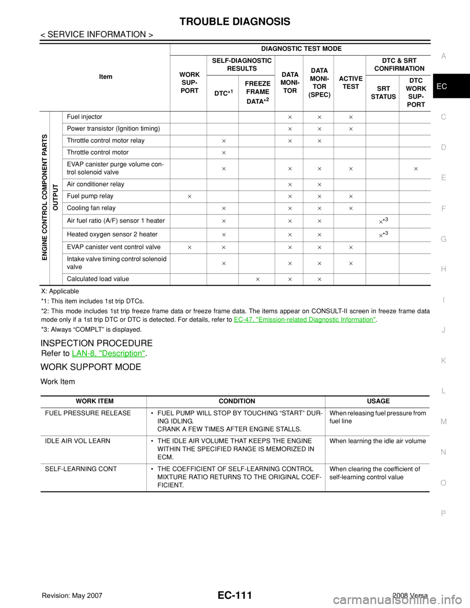
X: Applicable
*1: This item includes 1st trip DTCs.
*2: This mode includes 1st trip freeze frame data or freeze frame data. The items appear on CONSULT-II screen in freeze frame data
mode only if a 1st trip DTC or DTC is detected. For details, refer to EC-47, "
Emission-related Diagnostic Information".
*3: Always “COMPLT” is displayed.
INSPECTION PROCEDURE
Refer to LAN-8, "Description".
WORK SUPPORT MODE
Work Item
ENGINE CONTROL COMPONENT PARTS
OUTPUT
Fuel injector×× ×
Power transistor (Ignition timing)×× ×
Throttle control motor relay×××
Throttle control motor×
EVAP canister purge volume con-
trol solenoid valve×××××
Air conditioner relay××
Fuel pump relay××××
Cooling fan relay××××
Air fuel ratio (A/F) sensor 1 heater×××
×*
3
Heated oxygen sensor 2 heater×××
×*3
EVAP canister vent control valve×× ×××
Intake valve timing control solenoid
valve××××
Calculated load value××× ItemDIAGNOSTIC TEST MODE
WORK
SUP-
PORTSELF-DIAGNOSTIC
RESULTS
DATA
MONI-
TORDATA
MONI-
TOR
(SPEC)ACTIVE
TESTDTC & SRT
CONFIRMATION
DTC*
1 FREEZE
FRAME
DATA*
2
SRT
STATUSDTC
WORK
SUP-
PORT
WORK ITEM CONDITION USAGE
FUEL PRESSURE RELEASE • FUEL PUMP WILL STOP BY TOUCHING “START” DUR-
ING IDLING.
CRANK A FEW TIMES AFTER ENGINE STALLS.When releasing fuel pressure from
fuel line
IDLE AIR VOL LEARN • THE IDLE AIR VOLUME THAT KEEPS THE ENGINE
WITHIN THE SPECIFIED RANGE IS MEMORIZED IN
ECM.When learning the idle air volume
SELF-LEARNING CONT • THE COEFFICIENT OF SELF-LEARNING CONTROL
MIXTURE RATIO RETURNS TO THE ORIGINAL COEF-
FICIENT.When clearing the coefficient of
self-learning control value
Page 1188 of 2771
![NISSAN TIIDA 2008 Service Repair Manual EC-114
< SERVICE INFORMATION >
TROUBLE DIAGNOSIS
FUEL T/TMP SE [°C]
or [°F]ו The fuel temperature (determined by the signal
voltage of the fuel tank temperature sensor) is
displayed.
INT/A TE NISSAN TIIDA 2008 Service Repair Manual EC-114
< SERVICE INFORMATION >
TROUBLE DIAGNOSIS
FUEL T/TMP SE [°C]
or [°F]ו The fuel temperature (determined by the signal
voltage of the fuel tank temperature sensor) is
displayed.
INT/A TE](/manual-img/5/57399/w960_57399-1187.png)
EC-114
< SERVICE INFORMATION >
TROUBLE DIAGNOSIS
FUEL T/TMP SE [°C]
or [°F]ו The fuel temperature (determined by the signal
voltage of the fuel tank temperature sensor) is
displayed.
INT/A TEMP SE
[°C] or [°F]×ו The intake air temperature (determined by the
signal voltage of the intake air temperature
sensor) is indicated.
EVAP SYS PRES [V]ו The signal voltage of EVAP control system
pressure sensor is displayed.
FUEL LEVEL SE [V]ו The signal voltage of the fuel level sensor is
displayed.
START SIGNAL
[ON/OFF]×ו Indicates start signal status [ON/OFF] comput-
ed by the ECM according to the signals of en-
gine speed and battery voltage.• After starting the engine, [OFF] is
displayed regardless of the starter
signal.
CLSD THL POS
[ON/OFF]×ו Indicates idle position [ON/OFF] computed by
the ECM according to the accelerator pedal po-
sition sensor signal.
AIR COND SIG
[ON/OFF]×ו Indicates [ON/OFF] condition of the air condi-
tioner switch as determined by the air condi-
tioner signal.
P/N POSI SW
[ON/OFF]×ו Indicates [ON/OFF] condition from the park/
neutral position (PNP) switch signal.
PW/ST SIGNAL [ON/
OFF]×ו [ON/OFF] condition of the power steering sys-
tem (determined by the signal sent from EPS
control unit) is indicated.
LOAD SIGNAL
[ON/OFF]×ו Indicates [ON/OFF] condition from the electri-
cal load signal.
ON: Rear window defogger switch is ON and/
or lighting switch is in 2nd position.
OFF: Both rear window defogger switch and
lighting switch are OFF.
IGNITION SW
[ON/OFF]ו Indicates [ON/OFF] condition from ignition
switch.
HEATER FAN SW
[ON/OFF]ו Indicates [ON/OFF] condition from the heater
fan switch signal.
BRAKE SW
[ON/OFF]ו Indicates [ON/OFF] condition from the stop
lamp switch signal.
INJ PULSE-B1
[msec]ו Indicates the actual fuel injection pulse width
compensated by ECM according to the input
signals.• When the engine is stopped, a
certain computed value is indicat-
ed.
IGN TIMING [BTDC]• Indicates the ignition timing computed by ECM
according to the input signals.• When the engine is stopped, a
certain value is indicated.
CAL/LD VALUE [%]• “Calculated load value” indicates the value of
the current airflow divided by peak airflow.
MASS AIRFLOW
[g·m/s]• Indicates the mass airflow computed by ECM
according to the signal voltage of the mass air
flow sensor.
PURG VOL C/V [%]• Indicates the EVAP canister purge volume con-
trol solenoid valve control value computed by
the ECM according to the input signals.
• The opening becomes larger as the value in-
creases.
INT/V TIM (B1) [°CA]• Indicates [°CA] of intake camshaft advanced
angle. Monitored item [Unit]ECM IN-
PUT SIG-
NALSMAIN
SIG-
NALSDescription Remarks