2008 NISSAN TIIDA stop start
[x] Cancel search: stop startPage 795 of 2771
![NISSAN TIIDA 2008 Service Repair Manual BRC-30
< SERVICE INFORMATION >[ABS]
TROUBLE DIAGNOSES FOR SYMPTOMS
2. Drive vehicle and check brake operation.
NOTE:
• Stopping distance may be longer than vehicles without ABS when road condition i NISSAN TIIDA 2008 Service Repair Manual BRC-30
< SERVICE INFORMATION >[ABS]
TROUBLE DIAGNOSES FOR SYMPTOMS
2. Drive vehicle and check brake operation.
NOTE:
• Stopping distance may be longer than vehicles without ABS when road condition i](/manual-img/5/57399/w960_57399-794.png)
BRC-30
< SERVICE INFORMATION >[ABS]
TROUBLE DIAGNOSES FOR SYMPTOMS
2. Drive vehicle and check brake operation.
NOTE:
• Stopping distance may be longer than vehicles without ABS when road condition is slippery.
• Driving the vehicle with the ABS actuator and electric unit (control unit) disconnected may induce DTCs
in electrical control units using CAN communication. After the inspection, clear all DTCs. Refer to LAN-
6, "System Description".
OK or NG
OK >> GO TO 4.
NG >> Perform Basic Inspection. Refer to BRC-16, "
Basic Inspection".
4.CHECK WHEEL SENSORS
Check the following.
• Wheel sensor mounting for looseness
• Wheel sensors for physical damage
• Wheel sensor connectors for terminal damage or loose connections
• Sensor rotor and mount for physical damage
OK or NG
OK >> Check ABS actuator and electric unit (control unit) connector terminals for deformation, discon-
nection, looseness or damage. Reconnect ABS actuator and electric unit (control unit) harness
connector. Then retest.
NG >> Repair or replace as necessary.
Long Stopping DistanceINFOID:0000000001703847
1.CHECK BASE BRAKING SYSTEM PERFORMANCE
1. Disable ABS by disconnecting ABS actuator and electric unit (control unit) connector.
2. Drive vehicle and check brake operation.
NOTE:
• Stopping distance may be longer than vehicles without ABS when road condition is slippery.
• Driving the vehicle with the ABS actuator and electric unit (control unit) disconnected may induce DTCs
in electrical control units using CAN communication. After the inspection, clear all DTCs. Refer to LAN-
6, "System Description".
OK or NG
OK >> Go to BRC-29, "ABS Works Frequently".
NG >> Perform Basic Inspection. Refer to BRC-16, "
Basic Inspection".
ABS Does Not WorkINFOID:0000000001703848
CAUTION:
The ABS does not operate when the vehicle speed is 10 km/h (6 MPH) or less.
1.CHECK WARNING LAMP ACTIVATION
Turn ignition switch ON and check for warning lamp activation.
• Warning lamp should activate for approximately 2 seconds after turning the ignition switch ON.
OK or NG
OK >> Carry out self-diagnosis. Refer to BRC-18, "CONSULT-III Function (ABS)".
NG >> Go to BRC-16, "
Basic Inspection".
Pedal Vibration or ABS Operation NoiseINFOID:0000000001703849
NOTE:
During ABS activation, pedal vibration may be felt and a noise may be heard. This is normal and does not indi-
cate a malfunction.
1.CHECK SYMPTOM
1. Apply brake.
2. Start engine.
Does the symptom occur only when engine is started?
YES >> Carry out self-diagnosis. Refer to BRC-18, "CONSULT-III Function (ABS)".
Page 859 of 2771

CVT-20
< SERVICE INFORMATION >
CVT SYSTEM
Hydraulic Control System
INFOID:0000000001703438
TCM FunctionINFOID:0000000001703439
The function of the TCM is to:
• Receive input signals sent from various switches and sensors.
• Determine required line pressure, shifting point, and lock-up operation.
• Send required output signals to the step motor and the respective solenoids.
CONTROL SYSTEM OUTLINE
The CVT senses vehicle operating conditions through various sensors. It always controls the optimum shift
position and reduces shifting and lock-up shocks.
SCIA1807E
SENSORS (or SIGNAL)
⇒TCM
⇒ACTUATORS
PNP switch
Accelerator pedal position signal
Closed throttle position signal
Engine speed signal
CVT fluid temperature sensor
Vehicle speed signal
Overdrive control signal
Stop lamp switch signal
Primary speed sensor
Secondary speed sensor
Primary pressure sensor
Secondary pressure sensorShift control
Line pressure control
Primary pressure control
Secondary pressure control
Lock-up control
Engine brake control
Vehicle speed control
Fail-safe control
Self-diagnosis
CONSULT-III communication
line
Duet-EA control
CAN system
On board diagnosisSte p m ot or
Torque converter clutch solenoid
valve
Lock-up select solenoid valve
Line pressure solenoid valve
Secondary pressure solenoid
valve
Shift position indicator
O/D OFF indicator lamp
Starter relay
Page 880 of 2771

TROUBLE DIAGNOSIS
CVT-41
< SERVICE INFORMATION >
D
E
F
G
H
I
J
K
L
MA
B
CVT
N
O
P
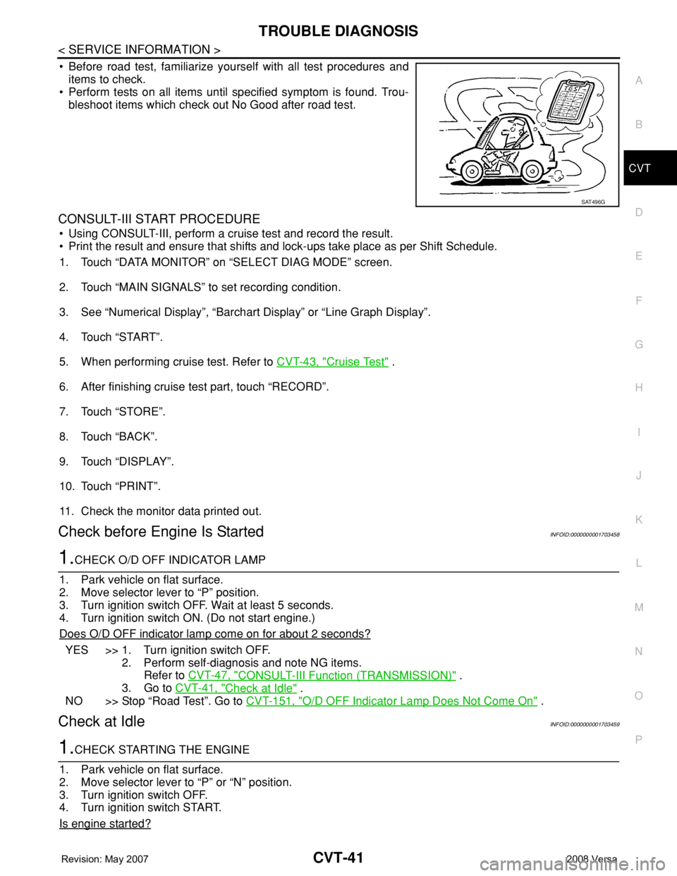
• Before road test, familiarize yourself with all test procedures and
items to check.
• Perform tests on all items until specified symptom is found. Trou-
bleshoot items which check out No Good after road test.
CONSULT-III START PROCEDURE
• Using CONSULT-III, perform a cruise test and record the result.
• Print the result and ensure that shifts and lock-ups take place as per Shift Schedule.
1. Touch “DATA MONITOR” on “SELECT DIAG MODE” screen.
2. Touch “MAIN SIGNALS” to set recording condition.
3. See “Numerical Display”, “Barchart Display” or “Line Graph Display”.
4. Touch “START”.
5. When performing cruise test. Refer to CVT-43, "
Cruise Test" .
6. After finishing cruise test part, touch “RECORD”.
7. Touch “STORE”.
8. Touch “BACK”.
9. Touch “DISPLAY”.
10. Touch “PRINT”.
11. Check the monitor data printed out.
Check before Engine Is StartedINFOID:0000000001703458
1.CHECK O/D OFF INDICATOR LAMP
1. Park vehicle on flat surface.
2. Move selector lever to “P” position.
3. Turn ignition switch OFF. Wait at least 5 seconds.
4. Turn ignition switch ON. (Do not start engine.)
Does O/D OFF indicator lamp come on for about 2 seconds?
YES >> 1. Turn ignition switch OFF.
2. Perform self-diagnosis and note NG items.
Refer to CVT-47, "
CONSULT-III Function (TRANSMISSION)" .
3. Go to CVT-41, "
Check at Idle" .
NO >> Stop “Road Test”. Go to CVT-151, "
O/D OFF Indicator Lamp Does Not Come On" .
Check at IdleINFOID:0000000001703459
1.CHECK STARTING THE ENGINE
1. Park vehicle on flat surface.
2. Move selector lever to “P” or “N” position.
3. Turn ignition switch OFF.
4. Turn ignition switch START.
Is engine started?
SAT496G
Page 881 of 2771

CVT-42
< SERVICE INFORMATION >
TROUBLE DIAGNOSIS
YES >> GO TO 2.
NO >> Stop “Road Test”. Mark the box on the CVT-30, "
How to Perform Trouble Diagnosis for Quick and
Accurate Repair" . Go to CVT-153, "Engine Cannot Be Started in "P" and "N" Position" .
2.CHECK STARTING THE ENGINE
1. Turn ignition switch ON.
2. Move selector lever to “D”, “L” or “R” position.
3. Turn ignition switch START.
Is engine started?
YES >> Stop “Road Test”. Mark the box on the CVT-30, "How to Perform Trouble Diagnosis for Quick and
Accurate Repair" . Go to CVT-153, "Engine Cannot Be Started in "P" and "N" Position" .
NO >> GO TO 3.
3.CHECK “P” POSITION FUNCTION
1. Move selector lever to “P” position.
2. Turn ignition switch OFF.
3. Release parking brake.
4. Push vehicle forward or backward.
5. Apply parking brake.
Does vehicle move when it is pushed forward or backward?
YES >> Mark the box CVT-153, "In "P" Position, Vehicle Moves Forward or Backward When Pushed" on
the CVT-30, "
How to Perform Trouble Diagnosis for Quick and Accurate Repair" . Continue “Road
Te s t ” .
NO >> GO TO 4.
4.CHECK “N” POSITION FUNCTION
1. Start engine.
2. Move selector lever to “N” position.
3. Release parking brake.
Does vehicle move forward or backward?
YES >> Mark the box CVT-154, "In "N" Position, Vehicle Moves" on the CVT-30, "How to Perform Trouble
Diagnosis for Quick and Accurate Repair" . Continue “Road Test”.
NO >> GO TO 5.
5.CHECK SHIFT SHOCK
1. Apply foot brake.
2. Move selector lever to “R” position.
Is there large shock when changing from
“N” to “R” position?
YES >> Mark the box CVT-154, "Large Shock "N" → "R" Position" on the CVT-30, "How to Perform Trou-
ble Diagnosis for Quick and Accurate Repair" . Continue “Road Test”.
NO >> GO TO 6.
6.CHECK “R” POSITION FUNCTION
Release foot brake for several seconds.
Does vehicle creep backward when foot brake is released?
YES >> GO TO 7.
NO >> Mark the box CVT-155, "
Vehicle Does Not Creep Backward in "R" Position" on the CVT-30, "How
to Perform Trouble Diagnosis for Quick and Accurate Repair" . Continue “Road Test”.
7.CHECK “D”, “L” POSITIONS FUNCTION
Move selector lever to “D” and “L” positions and check if vehicle creeps forward.
Does vehicle creep forward in all positions?
YES >> Go to CVT-43, "Cruise Test" .
NO >> Stop “Road Test”. Mark the box on the CVT-30, "
How to Perform Trouble Diagnosis for Quick and
Accurate Repair" . Go to CVT-156, "Vehicle Does Not Creep Forward in "D" or "L" Position" .
Page 902 of 2771

DTC P0703 STOP LAMP SWITCH CIRCUIT
CVT-63
< SERVICE INFORMATION >
D
E
F
G
H
I
J
K
L
MA
B
CVT
N
O
P
DTC P0703 STOP LAMP SWITCH CIRCUIT
DescriptionINFOID:0000000001703483
ON, OFF status of the stop lamp switch is sent via the CAN communication from the combination meter to
TCM using the signal.
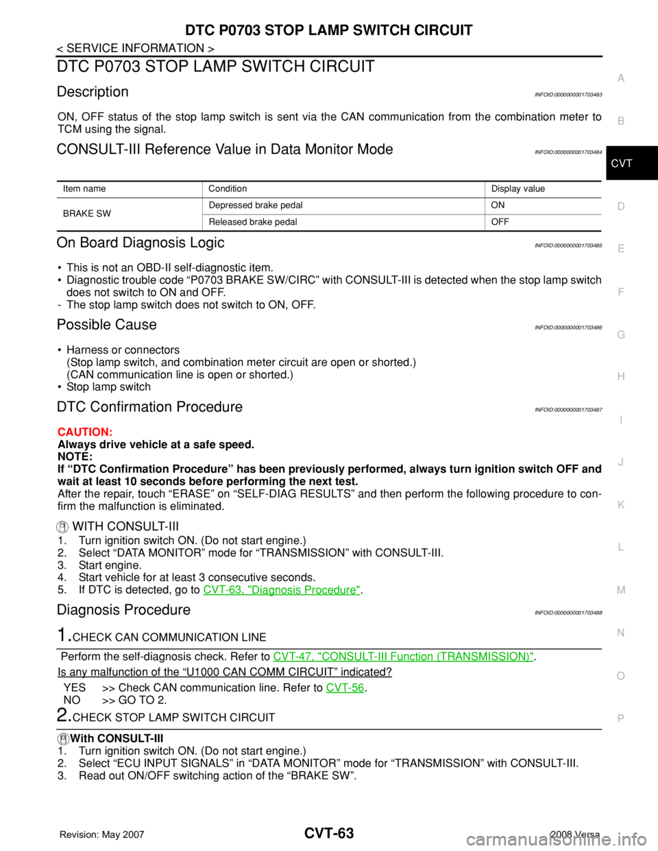
CONSULT-III Reference Value in Data Monitor ModeINFOID:0000000001703484
On Board Diagnosis LogicINFOID:0000000001703485
• This is not an OBD-II self-diagnostic item.
• Diagnostic trouble code “P0703 BRAKE SW/CIRC” with CONSULT-III is detected when the stop lamp switch
does not switch to ON and OFF.
- The stop lamp switch does not switch to ON, OFF.
Possible CauseINFOID:0000000001703486
• Harness or connectors
(Stop lamp switch, and combination meter circuit are open or shorted.)
(CAN communication line is open or shorted.)
• Stop lamp switch
DTC Confirmation ProcedureINFOID:0000000001703487
CAUTION:
Always drive vehicle at a safe speed.
NOTE:
If “DTC Confirmation Procedure” has been previously performed, always turn ignition switch OFF and
wait at least 10 seconds before performing the next test.
After the repair, touch “ERASE” on “SELF-DIAG RESULTS” and then perform the following procedure to con-
firm the malfunction is eliminated.
WITH CONSULT-III
1. Turn ignition switch ON. (Do not start engine.)
2. Select “DATA MONITOR” mode for “TRANSMISSION” with CONSULT-III.
3. Start engine.
4. Start vehicle for at least 3 consecutive seconds.
5. If DTC is detected, go to CVT-63, "
Diagnosis Procedure".
Diagnosis ProcedureINFOID:0000000001703488
1.CHECK CAN COMMUNICATION LINE
Perform the self-diagnosis check. Refer to CVT-47, "
CONSULT-III Function (TRANSMISSION)".
Is any malfunction of the
“U1000 CAN COMM CIRCUIT” indicated?
YES >> Check CAN communication line. Refer to CVT-56.
NO >> GO TO 2.
2.CHECK STOP LAMP SWITCH CIRCUIT
With CONSULT-III
1. Turn ignition switch ON. (Do not start engine.)
2. Select “ECU INPUT SIGNALS” in “DATA MONITOR” mode for “TRANSMISSION” with CONSULT-III.
3. Read out ON/OFF switching action of the “BRAKE SW”.
Item name Condition Display value
BRAKE SWDepressed brake pedal ON
Released brake pedal OFF
Page 926 of 2771

DTC P0730 BELT DAMAGE
CVT-87
< SERVICE INFORMATION >
D
E
F
G
H
I
J
K
L
MA
B
CVT
N
O
P
DTC P0730 BELT DAMAGE
DescriptionINFOID:0000000001703525
TCM selects the gear ratio using the engine load (throttle position), the primary pulley revolution speed, and
the secondary pulley revolution speed as input signal. Then it changes the operating pressure of the primary
pulley and the secondary pulley and changes the groove width of the pulley.
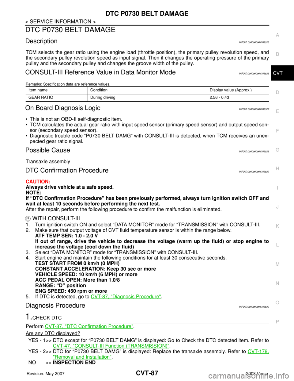
CONSULT-III Reference Value in Data Monitor ModeINFOID:0000000001703526
Remarks: Specification data are reference values.
On Board Diagnosis LogicINFOID:0000000001703527
• This is not an OBD-II self-diagnostic item.
• TCM calculates the actual gear ratio with input speed sensor (primary speed sensor) and output speed sen-
sor (secondary speed sensor).
• Diagnostic trouble code “P0730 BELT DAMG” with CONSULT-III is detected, when TCM receives an unex-
pected gear ratio signal.
Possible CauseINFOID:0000000001703528
Transaxle assembly
DTC Confirmation ProcedureINFOID:0000000001703529
CAUTION:
Always drive vehicle at a safe speed.
NOTE:
If “DTC Confirmation Procedure” has been previously performed, always turn ignition switch OFF and
wait at least 10 seconds before performing the next test.
After the repair, perform the following procedure to confirm the malfunction is eliminated.
WITH CONSULT-III
1. Turn ignition switch ON and select “DATA MONITOR” mode for “TRANSMISSION” with CONSULT-III.
2. Make sure that output voltage of CVT fluid temperature sensor is within the range below.
ATF TEMP SEN: 1.0 - 2.0 V
If out of range, drive the vehicle to decrease the voltage (warm up the fluid) or stop engine to
increase the voltage (cool down the fluid)
3. Select “DATA MONITOR” mode for “TRANSMISSION” with CONSULT-III.
4. Start engine and maintain the following conditions for at least 30 consecutive seconds.
TEST START FROM 0 km/h (0 MPH)
CONSTANT ACCELERATION: Keep 30 sec or more
VEHICLE SPEED: 10 km/h (6 MPH) or more
ACC PEDAL OPEN: More than 1.0/8
RANGE: “D” position
ENG SPEED: 450 rpm or more
5. If DTC is detected, go to CVT-87, "
Diagnosis Procedure".
Diagnosis ProcedureINFOID:0000000001703530
1.CHECK DTC
Perform CVT-87, "
DTC Confirmation Procedure".
Are any DTC displayed?
YES - 1>> DTC except for “P0730 BELT DAMG” is displayed: Go to Check the DTC detected item. Refer to
CVT-47, "
CONSULT-III Function (TRANSMISSION)".
YES - 2>> DTC for “P0730 BELT DAMG” is displayed: Replace the transaxle assembly. Refer to CVT-178,
"Removal and Installation".
NO >>INSPECTION END
Item name Condition Display value (Approx.)
GEAR RATIO During driving 2.56 - 0.43
Page 948 of 2771

DTC P0840 TRANSMISSION FLUID PRESSURE SENSOR A CIRCUIT (SEC
PRESSURE SENSOR)
CVT-109
< SERVICE INFORMATION >
D
E
F
G
H
I
J
K
L
MA
B
CVT
N
O
P
DTC P0840 TRANSMISSION FLUID PRESSURE SENSOR A CIRCUIT
(SEC PRESSURE SENSOR)
DescriptionINFOID:0000000001703573
• The transmission fluid pressure sensor A (secondary pressure sensor) is included in the control valve
assembly.
• The transmission fluid pressure sensor A (secondary pressure sensor) detects secondary pressure of CVT
and sends TCM the signal.
CONSULT-III Reference Value in Data Monitor ModeINFOID:0000000001703574
Remarks: Specification data are reference values.
On Board Diagnosis LogicINFOID:0000000001703575
• This is an OBD-II self-diagnostic item.
• Diagnostic trouble code “P0840 TR PRS SENS/A CIRC” with CONSULT-III is detected when TCM detects
an improper voltage drop when it receives the sensor signal.
Possible CauseINFOID:0000000001703576
• Transmission fluid pressure sensor A (Secondary pressure sensor)
• Harness or connectors
(Switch circuit is open or shorted.)
DTC Confirmation ProcedureINFOID:0000000001703577
NOTE:
If “DTC Confirmation Procedure” has been previously performed, always turn ignition switch OFF and
wait at least 10 seconds before performing the next test.
After the repair, perform the following procedure to confirm the malfunction is eliminated.
WITH CONSULT-III
1. Turn ignition switch ON and select “DATA MONITOR” mode for “TRANSMISSION” with CONSULT-III.
2. Make sure that output voltage of line temperature sensor is within the range below.
ATF TEMP SEN: 1.0 - 2.0 V
If out of range, drive the vehicle to decrease the voltage (warm up the fluid) or stop engine to
increase the voltage (cool down the fluid)
3. Start engine and wait for at least 5 consecutive seconds.
4. If DTC is detected, go to CVT-111, "
Diagnosis Procedure" .
WITH GST
Follow the procedure “WITH CONSULT-III”.
Item name Condition Display value (Approx.)
SEC HYDR SEN
“N” position idle1.0 V
SEC PRESS0.8 MPa
Page 954 of 2771

DTC P0845 TRANSMISSION FLUID PRESSURE SENSOR B CIRCUIT (PRI
PRESSURE SENSOR)
CVT-115
< SERVICE INFORMATION >
D
E
F
G
H
I
J
K
L
MA
B
CVT
N
O
P
DTC P0845 TRANSMISSION FLUID PRESSURE SENSOR B CIRCUIT (PRI
PRESSURE SENSOR)
DescriptionINFOID:0000000001703586
• The transmission fluid pressure sensor B (primary pressure sensor) is included in the control valve assem-
bly.
• The transmission fluid pressure sensor B (primary pressure sensor) detects primary pressure of CVT and
sends TCM the signal.
CONSULT-III Reference Value in Data Monitor ModeINFOID:0000000001703587
Remarks: Specification data are reference values.
On Board Diagnosis LogicINFOID:0000000001703588
• This is an OBD-II self-diagnostic item.
• Diagnostic trouble code “P0845 TR PRS SENS/B CIRC” with CONSULT-III is detected under the following
conditions.
- When TCM detects an improper voltage drop when it receives the sensor signal.
- When TCM compares target value with monitor value and detects an irregularity.
Possible CauseINFOID:0000000001703589
• Transmission fluid pressure sensor B (Primary pressure sensor)
• Harness or connectors
(Sensor circuit is open or shorted.)
DTC Confirmation ProcedureINFOID:0000000001703590
NOTE:
If “DTC Confirmation Procedure” has been previously performed, always turn ignition switch OFF and
wait at least 10 seconds before performing the next test.
After the repair, perform the following procedure to confirm the malfunction is eliminated.
WITH CONSULT-III
1. Turn ignition switch ON and select “DATA MONITOR” mode for “TRANSMISSION” with CONSULT-III.
2. Make sure that output voltage of line temperature sensor is within the range below.
ATF TEMP SEN: 1.0 - 2.0 V
If out of range, drive the vehicle to decrease the voltage (warm up the fluid) or stop engine to
increase the voltage (cool down the fluid)
3. Start engine and wait for at least 5 consecutive seconds.
4. If DTC is detected, go to CVT-117, "
Diagnosis Procedure" .
WITH GST
Follow the procedure “WITH CONSULT-III”.
Item name Condition Display value (Approx.)
PRI HYDR SEN “N” position idle 0.7 V