2008 NISSAN TIIDA stop start
[x] Cancel search: stop startPage 2702 of 2771
![NISSAN TIIDA 2008 Service Repair Manual TROUBLE DIAGNOSIS FOR SYSTEM
STC-19
< SERVICE INFORMATION >[EPS]
C
D
E
F
H
I
J
K
L
MA
B
STC
N
O
P
OK >>INSPECTION END
NG >> Perform self-diagnosis with ABS actuator and electric unit (control unit) an NISSAN TIIDA 2008 Service Repair Manual TROUBLE DIAGNOSIS FOR SYSTEM
STC-19
< SERVICE INFORMATION >[EPS]
C
D
E
F
H
I
J
K
L
MA
B
STC
N
O
P
OK >>INSPECTION END
NG >> Perform self-diagnosis with ABS actuator and electric unit (control unit) an](/manual-img/5/57399/w960_57399-2701.png)
TROUBLE DIAGNOSIS FOR SYSTEM
STC-19
< SERVICE INFORMATION >[EPS]
C
D
E
F
H
I
J
K
L
MA
B
STC
N
O
P
OK >>INSPECTION END
NG >> Perform self-diagnosis with ABS actuator and electric unit (control unit) and combination meter.
Refer to BRC-18, "
CONSULT-III Function (ABS)" , DI-13, "CONSULT-III Function (METER/M&A)"
.
DTC C1610 CAN ENG RPMINFOID:0000000001703889
CONSULT-III REFERENCE VALUE IN DATA MONITOR MODE
Data are reference value.
DIAGNOSTIC PROCEDURE
1.CHECK DTC WITH ECM
Perform self-diagnosis with ECM. Refer to EC-109, "
CONSULT-II Function (ENGINE)" .
Is any malfunction detected by self-diagnosis?
YES >> Check the malfunctioning system.
NO >> GO TO 2.
2.CHECK EPS CONTROL UNIT
Check EPS control unit input/output signal. Refer to STC-9, "
EPS Control Unit Input/Output Signal Reference
Va l u e" .
OK or NG
OK >> GO TO 3.
NG >> Check EPS control unit pin terminals for damage or loose connection with harness connector. If
any items are damaged, repair or replace damaged parts.
3.CHECK DTC
Perform the self-diagnosis, after driving a vehicle for a while.
OK or NG
OK >>INSPECTION END
NG >> Perform self-diagnosis with ECM again. Refer EC-109, "
CONSULT-II Function (ENGINE)" .
DTC U1000 CAN COMM CIRCUITINFOID:0000000001703890
DIAGNOSTIC PROCEDURE
1.CHECK CAN COMMUNICATION CIRCUIT
With CONSULT-III
1. Turn ignition switch “ON” and start engine.
2. Select “SELF-DIAG RESULTS” mode for “EPS” with CONSULT-III.
3. Perform the self-diagnosis.
Is the
“CAN COMM CIRCUIT [U1000]” displayed?
YES >> Print out CONSULT-III screen and go to LAN-15, "Trouble Diagnosis Flow Chart".
NO >>INSPECTION END
Component InspectionINFOID:0000000001703891
EPS MOTOR
1. Turn ignition switch “OFF”.
2. Disconnect EPS control unit harness connector.
Monitor item (Unit) Content Condition Display value
ENGINE STATUS (RUN/STOP) Engine statusEngine stopped (Engine speed: Less than 400 rpm) STOP
Engine running (Engine speed: 400 rpm or more) RUN
Page 2737 of 2771

WW-4
< SERVICE INFORMATION >
FRONT WIPER AND WASHER SYSTEM
• to front wiper high relay (located in IPDM E/R), and
• to CPU (located in IPDM E/R),
• through 10A fuse [No. 6, located in fuse block (J/B)]
• to BCM terminal 38,
• through 15A fuse [No. 4, located in fuse block (J/B)]
• to combination switch terminal 14.
Ground is supplied
• to IPDM E/R terminals 39 and 59, and
• to front wiper motor terminal 2
• through grounds E15 and E24
• to BCM terminal 67, and
• to combination switch terminal 12
• through grounds M57 and M61.
LOW SPEED WIPER OPERATION
When the front wiper switch is in LO position, the BCM detects the low speed wiper ON signal by means of the
BCM wiper switch reading function.
The BCM sends a front wiper request signal (LO) through the CAN communication line
• from BCM terminals 39 and 40
• to IPDM E/R terminals 40 and 41.
When the IPDM E/R receives front wiper request signal (LO), it turns ON front wiper relay, located in IPDM E/
R, power is supplied
• through IPDM E/R terminal 33 and front wiper high relay and front wiper relay
• to front wiper motor terminal 3.
Ground is supplied
• to front wiper motor terminal 2
• through grounds E15 and E24.
With power and ground is supplied, front wiper motor operates at low speed.
HIGH SPEED WIPER OPERATION
When the front wiper switch is in HI position, the BCM detects a high speed wiper ON signal by means of the
BCM wiper switch reading function.
The BCM sends a front wiper request signal (HI) through the CAN communication line
• from BCM terminals 39 and 40
• to IPDM E/R terminals 40 and 41.
When the IPDM E/R receives front wiper request signal (HI), it turns ON front wiper relay and front wiper high
relay, located in IPDM E/R, power is supplied
• through IPDM E/R terminal 32
• to front wiper motor terminal 5.
Ground is supplied
• to front wiper motor terminal 2
• through grounds E15 and E24.
With power and ground is supplied, front wiper motor operates at high speed.
INTERMITTENT OPERATION
Wiper intermittent operation delay interval is determined from the intermittent wiper dial position inputs. During
each intermittent operation delay interval, the BCM sends a front wiper request signal to the IPDM E/R to
operate the wipers.
When the ignition switch is in the ON or START position, and the front wiper switch is turned to the intermittent
position, the BCM detects a front wiper (intermittent) ON signal by means of the BCM wiper switch reading
function.
BCM then sends front wiper (intermittent) request signal through the CAN communication lines
• from BCM terminals 39 and 40
• to IPDM E/R terminals 40 and 41.
When BCM determines that combination switch status is front wiper intermittent ON, it performs the following
operations.
• BCM detects ON/OFF status of intermittent wiper dial position
• BCM calculates operation interval from wiper dial position.
• BCM sends a front wiper request signal (INT) to IPDM E/R at calculated operation interval.
When IPDM E/R receives the front wiper request signal (INT), it supplies ground to energize the front wiper
relay. It then sends auto-stop signal to the BCM and conducts intermittent front wiper motor operation.
Page 2746 of 2771

FRONT WIPER AND WASHER SYSTEM
WW-13
< SERVICE INFORMATION >
C
D
E
F
G
H
I
J
L
MA
B
WW
N
O
P
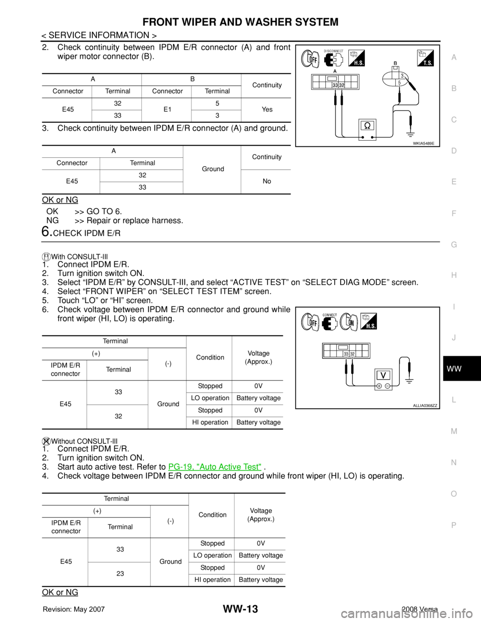
2. Check continuity between IPDM E/R connector (A) and front
wiper motor connector (B).
3. Check continuity between IPDM E/R connector (A) and ground.
OK or NG
OK >> GO TO 6.
NG >> Repair or replace harness.
6.CHECK IPDM E/R
With CONSULT-lIl
1. Connect IPDM E/R.
2. Turn ignition switch ON.
3. Select “IPDM E/R” by CONSULT-III, and select “ACTIVE TEST” on “SELECT DIAG MODE” screen.
4. Select “FRONT WIPER” on “SELECT TEST ITEM” screen.
5. Touch “LO” or “HI” screen.
6. Check voltage between IPDM E/R connector and ground while
front wiper (HI, LO) is operating.
Without CONSULT-llI1. Connect IPDM E/R.
2. Turn ignition switch ON.
3. Start auto active test. Refer to PG-19, "
Auto Active Test" .
4. Check voltage between IPDM E/R connector and ground while front wiper (HI, LO) is operating.
OK or NG
AB
Continuity
Connector Terminal Connector Terminal
E4532
E15
Ye s
33 3
A
GroundContinuity
Connector Terminal
E4532
No
33
WKIA5489E
Te r m i n a l
ConditionVo l ta g e
(Approx.) (+)
(-)
IPDM E/R
connectorTe r m i n a l
E4533
GroundStopped 0V
LO operation Battery voltage
32Stopped 0V
HI operation Battery voltage
Te r m i n a l
ConditionVol tag e
(Approx.) (+)
(-)
IPDM E/R
connectorTe r m i n a l
E4533
GroundStopped 0V
LO operation Battery voltage
23Stopped 0V
HI operation Battery voltage
ALLIA0368ZZ
Page 2758 of 2771

REAR WIPER AND WASHER SYSTEM
WW-25
< SERVICE INFORMATION >
C
D
E
F
G
H
I
J
L
MA
B
WW
N
O
P
• through grounds B117, B132 and D402.
With power and ground supplied, the rear wiper motor operates.
INTERMITTENT OPERATION
The rear wiper motor operates the wiper arm at low speed approximately every 7 seconds.
When the wiper switch is in the rear wiper INT position, the BCM detects a rear wiper INT request through the
combination switch (wiper switch) reading function.
When BCM operates rear wiper motor, power is supplied
• through BCM terminal 55
• to rear wiper motor terminal 1.
Ground is supplied
• to rear wiper motor terminal 3
• through grounds B117, B132 and D402.
With power and ground supplied, the rear wiper operates in intermittent mode.
AUTO STOP OPERATION
When the rear wiper arm is not located at the base of the rear window, and the rear wiper switch is turned
OFF, the rear wiper motor will continue to operate until the rear wiper arm is at the base of the rear window.
When the rear wiper arm reaches the base, rear wiper motor terminals 2 and 1 are connected.
Ground is supplied
• to BCM terminal 44
• through rear wiper motor terminal 2, and
• through rear wiper motor terminal 3, and
• through grounds B117, B132 and D402.
REAR WASHER OPERATION
When the ignition switch is in the ON or START position, and the front and rear washer switches are OFF, the
front and rear washer motor is supplied power
• through 15A fuse [No. 4, located in the fuse block (J/B)]
• to combination switch (wiper switch) terminal 14
• through combination switch (wiper switch) terminal 11
• to front and rear washer motor terminal 2.
When the rear wiper switch is in rear washer position, the BCM detects a rear washer signal by BCM wiper
switch reading function. Combination switch ground is supplied
• to front and rear washer motor terminal 1
• through combination switch (wiper switch) terminal 13, and
• through combination switch (wiper switch) terminal 12
• through grounds M57 and M61.
With ground supplied, the front and rear washer motor is operated in the rear direction.
When the BCM detects that the rear washer motor has operated for 0.4 seconds or longer, BCM operates the
rear wiper motor.
When the BCM detects that the rear washer switch is in OFF, the rear wiper motor cycles approximately 3
times and then stops.
If the rear washer is operated with the rear wiper switch in the INT position, normal rear wiper operation will
take over. Once the rear washer switch is released the rear wiper will return to INT operation.
BCM Combination Switch Reading Function
Refer to BCS-3, "System Description" .