2008 NISSAN TIIDA interior
[x] Cancel search: interiorPage 2239 of 2771
LT-102
< SERVICE INFORMATION >
INTERIOR ROOM LAMP
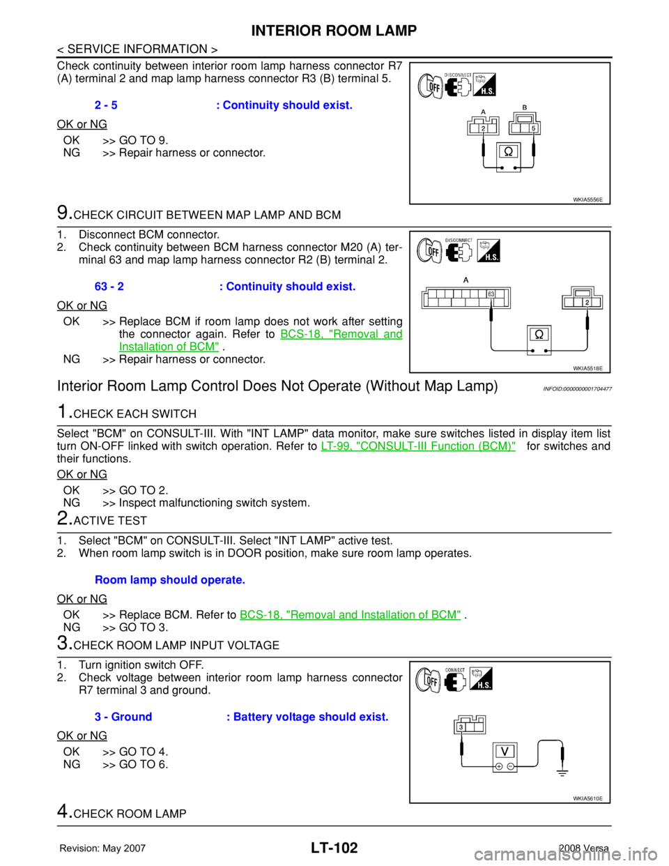
Check continuity between interior room lamp harness connector R7
(A) terminal 2 and map lamp harness connector R3 (B) terminal 5.
OK or NG
OK >> GO TO 9.
NG >> Repair harness or connector.
9.CHECK CIRCUIT BETWEEN MAP LAMP AND BCM
1. Disconnect BCM connector.
2. Check continuity between BCM harness connector M20 (A) ter-
minal 63 and map lamp harness connector R2 (B) terminal 2.
OK or NG
OK >> Replace BCM if room lamp does not work after setting
the connector again. Refer to BCS-18, "
Removal and
Installation of BCM" .
NG >> Repair harness or connector.
Interior Room Lamp Control Does Not Operate (Without Map Lamp)INFOID:0000000001704477
1.CHECK EACH SWITCH
Select "BCM" on CONSULT-III. With "INT LAMP" data monitor, make sure switches listed in display item list
turn ON-OFF linked with switch operation. Refer to LT-99, "
CONSULT-III Function (BCM)" for switches and
their functions.
OK or NG
OK >> GO TO 2.
NG >> Inspect malfunctioning switch system.
2.ACTIVE TEST
1. Select "BCM" on CONSULT-III. Select "INT LAMP" active test.
2. When room lamp switch is in DOOR position, make sure room lamp operates.
OK or NG
OK >> Replace BCM. Refer to BCS-18, "Removal and Installation of BCM" .
NG >> GO TO 3.
3.CHECK ROOM LAMP INPUT VOLTAGE
1. Turn ignition switch OFF.
2. Check voltage between interior room lamp harness connector
R7 terminal 3 and ground.
OK or NG
OK >> GO TO 4.
NG >> GO TO 6.
4.CHECK ROOM LAMP 2 - 5 : Continuity should exist.
WKIA5556E
63 - 2 : Continuity should exist.
WKIA5518E
Room lamp should operate.
3 - Ground : Battery voltage should exist.
WKIA5610E
Page 2240 of 2771
INTERIOR ROOM LAMP
LT-103
< SERVICE INFORMATION >
C
D
E
F
G
H
I
J
L
MA
B
LT
N
O
P
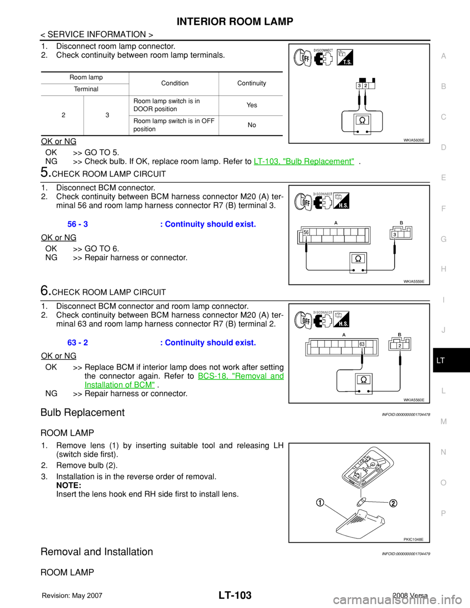
1. Disconnect room lamp connector.
2. Check continuity between room lamp terminals.
OK or NG
OK >> GO TO 5.
NG >> Check bulb. If OK, replace room lamp. Refer to LT-103, "
Bulb Replacement" .
5.CHECK ROOM LAMP CIRCUIT
1. Disconnect BCM connector.
2. Check continuity between BCM harness connector M20 (A) ter-
minal 56 and room lamp harness connector R7 (B) terminal 3.
OK or NG
OK >> GO TO 6.
NG >> Repair harness or connector.
6.CHECK ROOM LAMP CIRCUIT
1. Disconnect BCM connector and room lamp connector.
2. Check continuity between BCM harness connector M20 (A) ter-
minal 63 and room lamp harness connector R7 (B) terminal 2.
OK or NG
OK >> Replace BCM if interior lamp does not work after setting
the connector again. Refer to BCS-18, "
Removal and
Installation of BCM" .
NG >> Repair harness or connector.
Bulb ReplacementINFOID:0000000001704478
ROOM LAMP
1. Remove lens (1) by inserting suitable tool and releasing LH
(switch side first).
2. Remove bulb (2).
3. Installation is in the reverse order of removal.
NOTE:
Insert the lens hook end RH side first to install lens.
Removal and InstallationINFOID:0000000001704479
ROOM LAMP
Room lamp
Condition Continuity
Te r m i n a l
23 Room lamp switch is in
DOOR positionYe s
Room lamp switch is in OFF
positionNo
WKIA5609E
56 - 3 : Continuity should exist.
WKIA5559E
63 - 2 : Continuity should exist.
WKIA5560E
PKIC1048E
Page 2241 of 2771
LT-104
< SERVICE INFORMATION >
INTERIOR ROOM LAMP
Removal
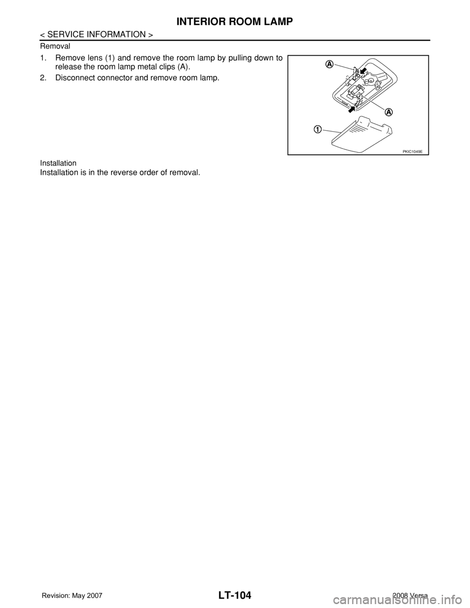
1. Remove lens (1) and remove the room lamp by pulling down to
release the room lamp metal clips (A).
2. Disconnect connector and remove room lamp.
Installation
Installation is in the reverse order of removal.
PKIC1049E
Page 2250 of 2771

BULB SPECIFICATIONS
LT-113
< SERVICE INFORMATION >
C
D
E
F
G
H
I
J
L
MA
B
LT
N
O
P
BULB SPECIFICATIONS
HeadlampINFOID:0000000001704485
Exterior LampINFOID:0000000001704486
Interior Lamp/IlluminationINFOID:0000000001704487
Item Wattage (W)
High/Low (Halogen type)60/55 (HB2)
Item Wattage (W)
Front combination lampTurn signal lamp 21 (amber)
Parking (clearance) lamp 5
Rear combination lampStop/Tail lamp 21/5
Turn signal lamp 21 (amber)
Back-up lamp 21
Front fog lamp35 (H8)
License plate lamp5
High-mounted stop lamp Hatchback LED
Sedan 18
Item Wattage (W)
Glove box lamp1.4
Map lamp8
Room lamp8
Luggage compartment lamp5
Page 2347 of 2771
PRECAUTIONS
MTC-9
< SERVICE INFORMATION >
C
D
E
F
G
H
I
K
L
MA
B
MTC
N
O
P
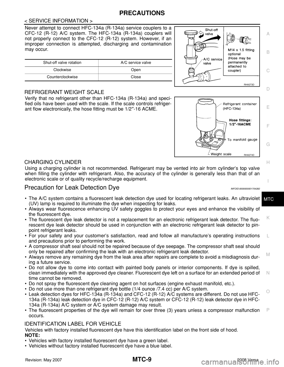
Never attempt to connect HFC-134a (R-134a) service couplers to a
CFC-12 (R-12) A/C system. The HFC-134a (R-134a) couplers will
not properly connect to the CFC-12 (R-12) system. However, if an
improper connection is attempted, discharging and contamination
may occur.
REFRIGERANT WEIGHT SCALE
Verify that no refrigerant other than HFC-134a (R-134a) and speci-
fied oils have been used with the scale. If the scale controls refriger-
ant flow electronically, the hose fitting must be 1/2″-16 ACME.
CHARGING CYLINDER
Using a charging cylinder is not recommended. Refrigerant may be vented into air from cylinder’s top valve
when filling the cylinder with refrigerant. Also, the accuracy of the cylinder is generally less than that of an
electronic scale or of quality recycle/recharge equipment.
Precaution for Leak Detection DyeINFOID:0000000001704282
• The A/C system contains a fluorescent leak detection dye used for locating refrigerant leaks. An ultraviolet
(UV) lamp is required to illuminate the dye when inspecting for leaks.
• Always wear fluorescence enhancing UV safety goggles to protect your eyes and enhance the visibility of
the fluorescent dye.
• The fluorescent dye leak detector is not a replacement for an electronic refrigerant leak detector. The fluo-
rescent dye leak detector should be used in conjunction with an electronic refrigerant leak detector to pin-
point refrigerant leaks.
• For your safety and your customer’s satisfaction, read and follow all manufacture’s operating instructions
and precautions prior to performing the work.
• A compressor shaft seal should not be repaired because of dye seepage. The compressor shaft seal should
only be repaired after confirming the leak with an electronic refrigerant leak detector.
• Always remove any remaining dye from the leak area after repairs are complete to avoid a misdiagnosis dur-
ing a future service.
• Do not allow dye to come into contact with painted body panels or interior components. If dye is spilled,
clean immediately with the approved dye cleaner. Fluorescent dye left on a surface for an extended period of
time cannot be removed.
• Do not spray the fluorescent dye cleaning agent on hot surfaces (engine exhaust manifold, etc.).
• Do not use more than one refrigerant dye bottle (1/4 ounce /7.4 cc) per A/C system.
• Leak detection dyes for HFC-134a (R-134a) and CFC-12 (R-12) A/C systems are different. Do not use HFC-
134a (R-134a) leak detection dye in CFC-12 (R-12) A/C system or CFC-12 (R-12) leak detector dye in HFC-
134a (R-134a) A/C system or A/C system damage may result.
• The fluorescent properties of the dye will remain for over three (3) years unless a compressor malfunction
occurs.
IDENTIFICATION LABEL FOR VEHICLE
Vehicles with factory installed fluorescent dye have this identification label on the front side of hood.
NOTE:
• Vehicles with factory installed fluorescent dye have a green label.
• Vehicles without factory installed fluorescent dye have a blue label.
Shut-off valve rotation A/C service valve
Clockwise Open
Counterclockwise Close
RHA273D
RHA274D
Page 2357 of 2771
AIR CONDITIONER CONTROL
MTC-19
< SERVICE INFORMATION >
C
D
E
F
G
H
I
K
L
MA
B
MTC
N
O
P
AIR CONDITIONER CONTROL
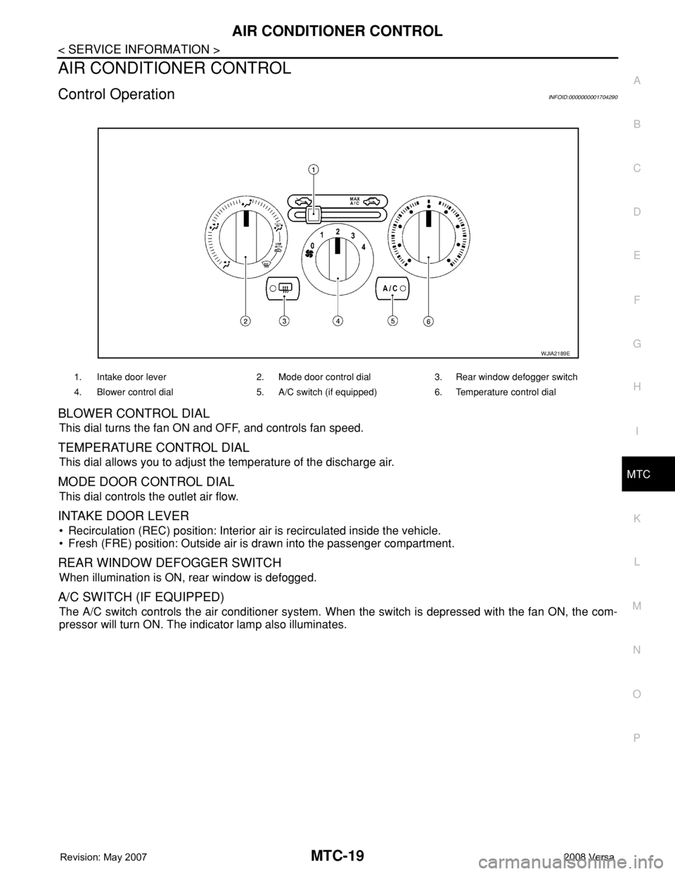
Control OperationINFOID:0000000001704290
BLOWER CONTROL DIAL
This dial turns the fan ON and OFF, and controls fan speed.
TEMPERATURE CONTROL DIAL
This dial allows you to adjust the temperature of the discharge air.
MODE DOOR CONTROL DIAL
This dial controls the outlet air flow.
INTAKE DOOR LEVER
• Recirculation (REC) position: Interior air is recirculated inside the vehicle.
• Fresh (FRE) position: Outside air is drawn into the passenger compartment.
REAR WINDOW DEFOGGER SWITCH
When illumination is ON, rear window is defogged.
A/C SWITCH (IF EQUIPPED)
The A/C switch controls the air conditioner system. When the switch is depressed with the fan ON, the com-
pressor will turn ON. The indicator lamp also illuminates.
1. Intake door lever 2. Mode door control dial 3. Rear window defogger switch
4. Blower control dial 5. A/C switch (if equipped) 6. Temperature control dial
WJIA2189E
Page 2486 of 2771
HARNESS
PG-53
< SERVICE INFORMATION >
C
D
E
F
G
H
I
J
L
MA
B
PG
N
O
P
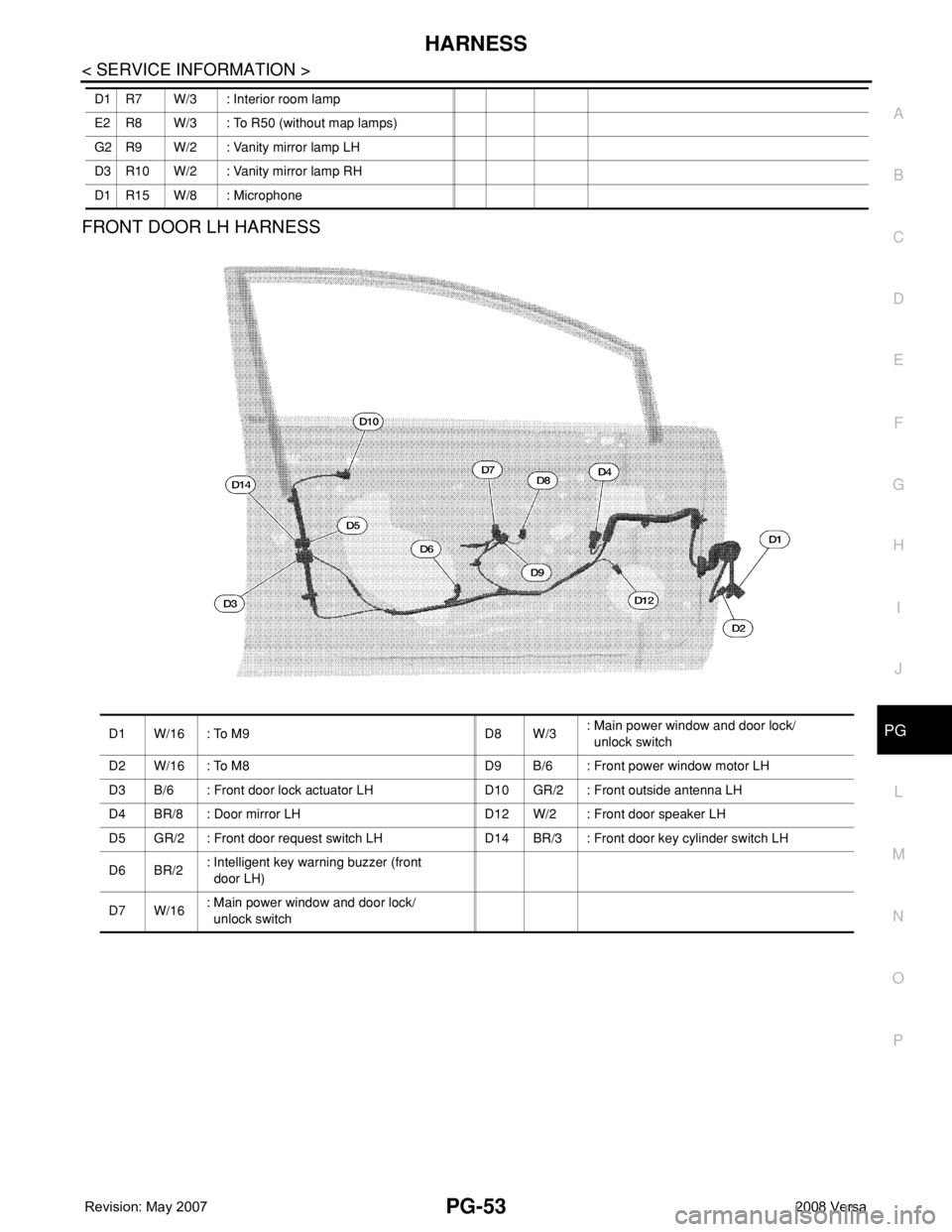
FRONT DOOR LH HARNESS
D1 R7 W/3 : Interior room lamp
E2 R8 W/3 : To R50 (without map lamps)
G2 R9 W/2 : Vanity mirror lamp LH
D3 R10 W/2 : Vanity mirror lamp RH
D1 R15 W/8 : Microphone
D1 W/16 : To M9 D8 W/3: Main power window and door lock/
unlock switch
D2 W/16 : To M8 D9 B/6 : Front power window motor LH
D3 B/6 : Front door lock actuator LH D10 GR/2 : Front outside antenna LH
D4 BR/8 : Door mirror LH D12 W/2 : Front door speaker LH
D5 GR/2 : Front door request switch LH D14 BR/3 : Front door key cylinder switch LH
D6 BR/2: Intelligent key warning buzzer (front
door LH)
D7 W/16: Main power window and door lock/
unlock switch
Page 2537 of 2771

SQUEAK AND RATTLE TROUBLE DIAGNOSES
RF-7
< SYMPTOM DIAGNOSIS >
C
D
E
F
G
H
J
K
L
MA
B
RF
N
O
P
2. Trunk lid striker out of adjustment
3. The trunk lid torsion bars knocking together
4. A loose license plate or bracket
Most of these incidents can be repaired by adjusting, securing or insulating the item(s) or component(s) caus-
ing the noise.
SUNROOF/HEADLINING
Noises in the sunroof/headlining area can often be traced to one of the following:
1. Sunroof lid, rail, linkage or seals making a rattle or light knocking noise
2. Sun visor shaft shaking in the holder
3. Front or rear windshield touching headliner and squeaking
Again, pressing on the components to stop the noise while duplicating the conditions can isolate most of these
incidents. Repairs usually consist of insulating with felt cloth tape.
OVERHEAD CONSOLE (FRONT AND REAR)
Overhead console noises are often caused by the console panel clips not being engaged correctly. Most of
these incidents are repaired by pushing up on the console at the clip locations until the clips engage.
In addition look for:
1. Loose harness or harness connectors.
2. Front console map/reading lamp lens loose.
3. Loose screws at console attachment points.
SEATS
When isolating seat noise it's important to note the position the seat is in and the load placed on the seat when
the noise is present. These conditions should be duplicated when verifying and isolating the cause of the
noise.
Cause of seat noise include:
1. Headrest rods and holder
2. A squeak between the seat pad cushion and frame
3. The rear seatback lock and bracket
These noises can be isolated by moving or pressing on the suspected components while duplicating the con-
ditions under which the noise occurs. Most of these incidents can be repaired by repositioning the component
or applying urethane tape to the contact area.
UNDERHOOD
Some interior noise may be caused by components under the hood or on the engine wall. The noise is then
transmitted into the passenger compartment.
Causes of transmitted underhood noise include:
1. Any component installed on the engine wall
2. Components that pass through the engine wall
3. Engine wall mounts and connectors
4. Loose radiator pins
5. Hood bumpers out of adjustment
6. Hood striker out of adjustment
These noises can be difficult to isolate since they cannot be reached from the interior of the vehicle. The best
method is to secure, move or insulate one component at a time and test drive the vehicle. Also, engine RPM
or load can be changed to isolate the noise. Repairs can usually be made by moving, adjusting, securing, or
insulating the component causing the noise.