Page 315 of 2771
REPAIR FOR COMPONENT PARTS
AT-303
< SERVICE INFORMATION >
D
E
F
G
H
I
J
K
L
MA
B
AT
N
O
P
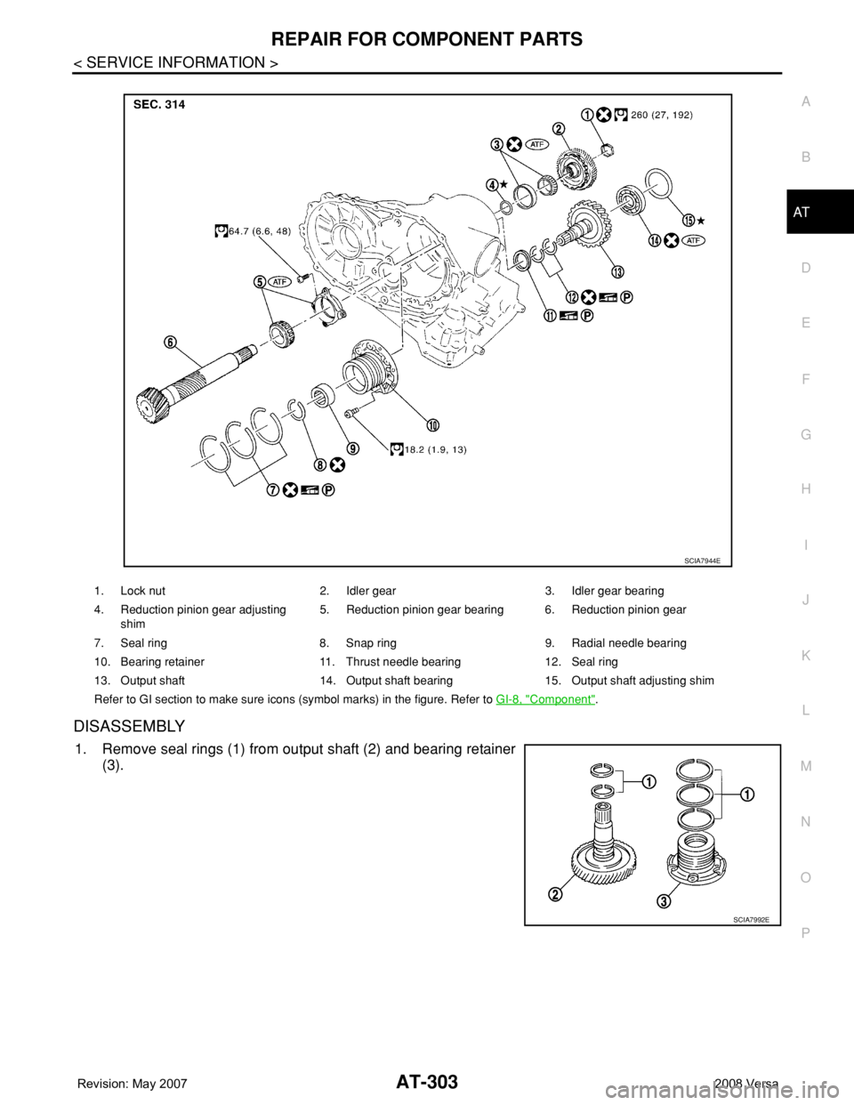
DISASSEMBLY
1. Remove seal rings (1) from output shaft (2) and bearing retainer
(3).
1. Lock nut 2. Idler gear 3. Idler gear bearing
4. Reduction pinion gear adjusting
shim5. Reduction pinion gear bearing 6. Reduction pinion gear
7. Seal ring 8. Snap ring 9. Radial needle bearing
10. Bearing retainer 11. Thrust needle bearing 12. Seal ring
13. Output shaft 14. Output shaft bearing 15. Output shaft adjusting shim
Refer to GI section to make sure icons (symbol marks) in the figure. Refer to GI-8, "
Component".
SCIA7944E
SCIA7992E
Page 316 of 2771
AT-304
< SERVICE INFORMATION >
REPAIR FOR COMPONENT PARTS
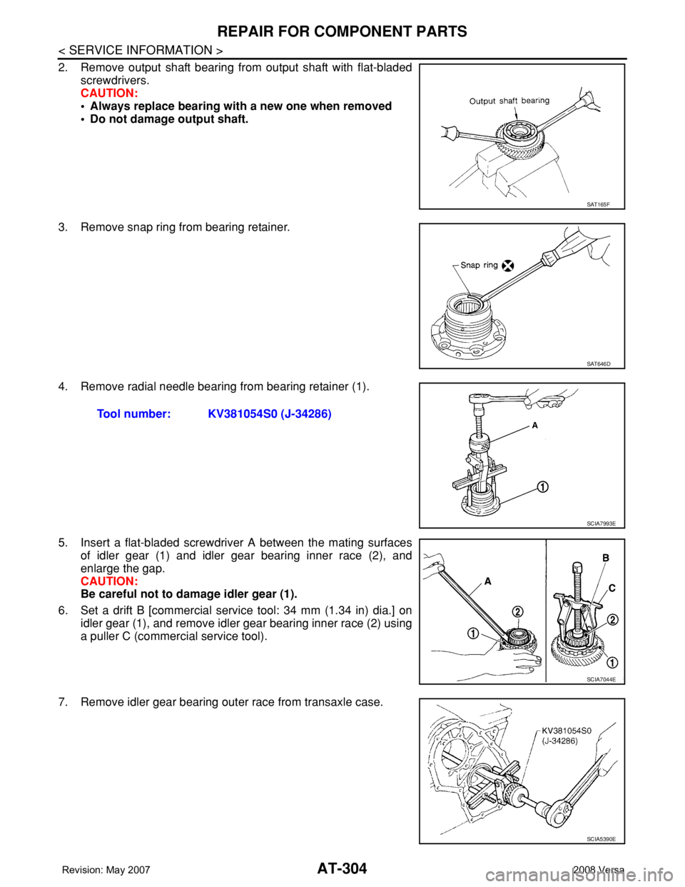
2. Remove output shaft bearing from output shaft with flat-bladed
screwdrivers.
CAUTION:
• Always replace bearing with a new one when removed
• Do not damage output shaft.
3. Remove snap ring from bearing retainer.
4. Remove radial needle bearing from bearing retainer (1).
5. Insert a flat-bladed screwdriver A between the mating surfaces
of idler gear (1) and idler gear bearing inner race (2), and
enlarge the gap.
CAUTION:
Be careful not to damage idler gear (1).
6. Set a drift B [commercial service tool: 34 mm (1.34 in) dia.] on
idler gear (1), and remove idler gear bearing inner race (2) using
a puller C (commercial service tool).
7. Remove idler gear bearing outer race from transaxle case.
SAT165F
SAT646D
Tool number: KV381054S0 (J-34286)
SCIA7993E
SCIA7044E
SCIA5390E
Page 317 of 2771
REPAIR FOR COMPONENT PARTS
AT-305
< SERVICE INFORMATION >
D
E
F
G
H
I
J
K
L
MA
B
AT
N
O
P
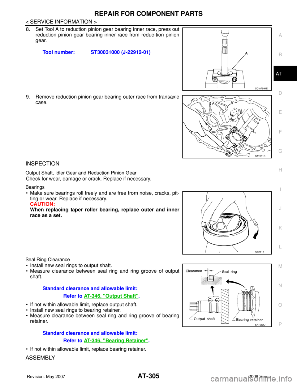
8. Set Tool A to reduction pinion gear bearing inner race, press out
reduction pinion gear bearing inner race from reduc-tion pinion
gear.
9. Remove reduction pinion gear bearing outer race from transaxle
case.
INSPECTION
Output Shaft, Idler Gear and Reduction Pinion Gear
Check for wear, damage or crack. Replace if necessary.
Bearings
• Make sure bearings roll freely and are free from noise, cracks, pit-
ting or wear. Replace if necessary.
CAUTION:
When replacing taper roller bearing, replace outer and inner
race as a set.
Seal Ring Clearance
• Install new seal rings to output shaft.
• Measure clearance between seal ring and ring groove of output
shaft.
• If not within allowable limit, replace output shaft.
• Install new seal rings to bearing retainer.
• Measure clearance between seal ring and ring groove of bearing
retainer.
• If not within allowable limit, replace bearing retainer.
ASSEMBLY
Tool number: ST30031000 (J-22912-01)
SCIA7994E
SAT651D
SPD715
Standard clearance and allowable limit:
Refer to AT-346, "
Output Shaft".
Standard clearance and allowable limit:
Refer to AT-346, "
Bearing Retainer".
SAT652D
Page 318 of 2771
AT-306
< SERVICE INFORMATION >
REPAIR FOR COMPONENT PARTS
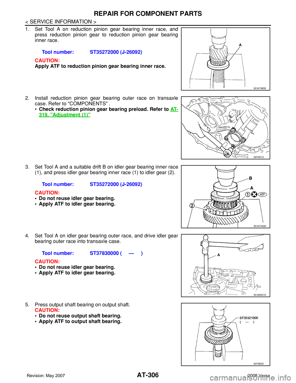
1. Set Tool A on reduction pinion gear bearing inner race, and
press reduction pinion gear to reduction pinion gear bearing
inner race.
CAUTION:
Apply ATF to reduction pinion gear bearing inner race.
2. Install reduction pinion gear bearing outer race on transaxle
case. Refer to "COMPONENTS" .
•Check reduction pinion gear bearing preload. Refer to AT-
319, "Adjustment (1)"
3. Set Tool A and a suitable drift B on idler gear bearing inner race
(1), and press idler gear bearing inner race (1) to idler gear (2).
CAUTION:
• Do not reuse idler gear bearing.
• Apply ATF to idler gear bearing.
4. Set Tool A on idler gear bearing outer race, and drive idler gear
bearing outer race into transaxle case.
CAUTION:
• Do not reuse idler gear bearing.
• Apply ATF to idler gear bearing.
5. Press output shaft bearing on output shaft.
CAUTION:
• Do not reuse output shaft bearing.
• Apply ATF to output shaft bearing.Tool number: ST35272000 (J-26092)
SCIA7995E
SAT651D
Tool number: ST35272000 (J-26092)
SCIA7046E
Tool number: ST37830000 ( — )
SCIA8031E
SAT863D
Page 319 of 2771
REPAIR FOR COMPONENT PARTS
AT-307
< SERVICE INFORMATION >
D
E
F
G
H
I
J
K
L
MA
B
AT
N
O
P
6. Set drift [commercial service tool] on radial needle bearing, and
press radial needle bearing into bearing retainer.
7. Install snap ring to bearing retainer.
8. After packing ring grooves with petroleum jelly, carefully install
new seal rings (1) on output shaft (2) and bearing retainer (3).
CAUTION:
Roll paper around seal rings to prevent seal rings from
spreading.
Band Servo Piston AssemblyINFOID:0000000001703389
COMPONENTS
SAT658D
SAT659D
SCIA7996E
SCIA8011E
Page 325 of 2771
REPAIR FOR COMPONENT PARTS
AT-313
< SERVICE INFORMATION >
D
E
F
G
H
I
J
K
L
MA
B
AT
N
O
P
11. Push in OD servo piston assembly using a puller A (commercial
service tool) and a suitable drift B, and install snap ring (1) to
transaxle case using a flat-bladed screwdriver C.
Final DriveINFOID:0000000001703390
COMPONENTS
DISASSEMBLY
1. Remove final gear (1) from differential case (2).
SCIA7050E
1. Pinion mate gear 2. Pinion mate gear thrust washer 3. Pinion mate shaft
4. Lock pin 5. Side gear 6. Side gear thrust washer
7. Differential side bearing 8. Speedometer drive gear 9. Differential case
10. Final gear 11. Differential side bearing 12. Differential side bearing adjusting
shim
Refer to GI section to make sure icons (symbol marks) in the figure. Refer to GI-8, "
Component".
SCIA7962E
SCIA8003E
Page 326 of 2771
AT-314
< SERVICE INFORMATION >
REPAIR FOR COMPONENT PARTS
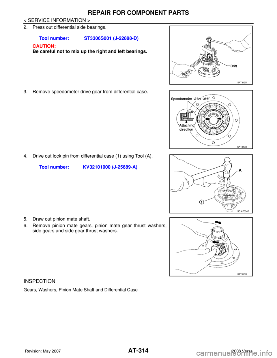
2. Press out differential side bearings.
CAUTION:
Be careful not to mix up the right and left bearings.
3. Remove speedometer drive gear from differential case.
4. Drive out lock pin from differential case (1) using Tool (A).
5. Draw out pinion mate shaft.
6. Remove pinion mate gears, pinion mate gear thrust washers,
side gears and side gear thrust washers.
INSPECTION
Gears, Washers, Pinion Mate Shaft and Differential Case
Tool number: ST3306S001 (J-22888-D)
SAT312D
SAT313D
Tool number: KV32101000 (J-25689-A)
SCIA7034E
SAT316D
Page 327 of 2771
REPAIR FOR COMPONENT PARTS
AT-315
< SERVICE INFORMATION >
D
E
F
G
H
I
J
K
L
MA
B
AT
N
O
P
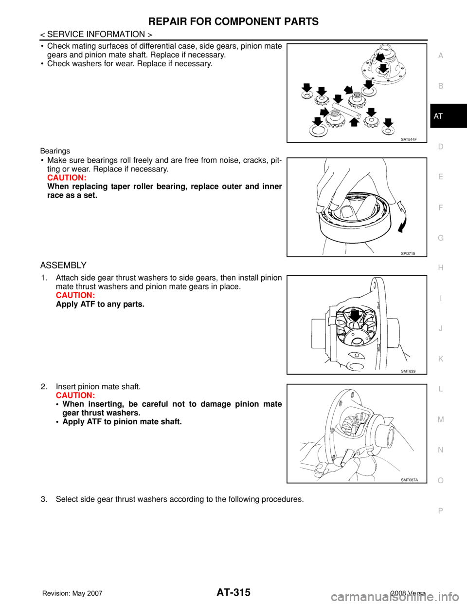
• Check mating surfaces of differential case, side gears, pinion mate
gears and pinion mate shaft. Replace if necessary.
• Check washers for wear. Replace if necessary.
Bearings
• Make sure bearings roll freely and are free from noise, cracks, pit-
ting or wear. Replace if necessary.
CAUTION:
When replacing taper roller bearing, replace outer and inner
race as a set.
ASSEMBLY
1. Attach side gear thrust washers to side gears, then install pinion
mate thrust washers and pinion mate gears in place.
CAUTION:
Apply ATF to any parts.
2. Insert pinion mate shaft.
CAUTION:
• When inserting, be careful not to damage pinion mate
gear thrust washers.
• Apply ATF to pinion mate shaft.
3. Select side gear thrust washers according to the following procedures.
SAT544F
SPD715
SMT839
SMT087A
![NISSAN TIIDA 2008 Service Repair Manual REPAIR FOR COMPONENT PARTS
AT-307
< SERVICE INFORMATION >
D
E
F
G
H
I
J
K
L
MA
B
AT
N
O
P
6. Set drift [commercial service tool] on radial needle bearing, and
press radial needle bearing into bearing](/manual-img/5/57399/w960_57399-318.png "NISSAN TIIDA 2008 Service Repair Manual REPAIR FOR COMPONENT PARTS
AT-307
< SERVICE INFORMATION >
D
E
F
G
H
I
J
K
L
MA
B
AT
N
O
P
6. Set drift [commercial service tool] on radial needle bearing, and
press radial needle bearing into bearing")