Page 266 of 2771
AT-254
< SERVICE INFORMATION >
DISASSEMBLY
c. Remove output shaft adjusting shim.
d. Remove output shaft assembly.
• If output shaft assembly came off with side cover, tap side-
cover with a soft hammer to separate.
CAUTION:
Be careful not to damage side cover.
e. Remove needle bearing.
•Check needle bearing, and replace if damaged or worn.
46. Disassemble reduction pinion gear according to the followingprocedures.
SAT440D
SAT035F
SAT435D
SCIA4879E
Page 267 of 2771
DISASSEMBLY
AT-255
< SERVICE INFORMATION >
D
E
F
G
H
I
J
K
L
MA
B
AT
N
O
P
a. Set manual shaft to “P” position to fix idler gear.
b. Unlock idler gear lock nut with pin punch.
c. Remove idler gear lock nut.
d. Remove idler gear with puller.
e. Remove reduction pinion gear.
f. Remove reduction pinion gear adjusting shim from reduction
pinion gear.
47. Remove bearing retainer fitting bolts, and then remove bearing
retainer (1) from transaxle case.
SAT037F
SAT061D
SCIA5380E
SCIA4880E
SCIA5909J
Page 301 of 2771

REPAIR FOR COMPONENT PARTS
AT-289
< SERVICE INFORMATION >
D
E
F
G
H
I
J
K
L
MA
B
AT
N
O
P
DISASSEMBLY
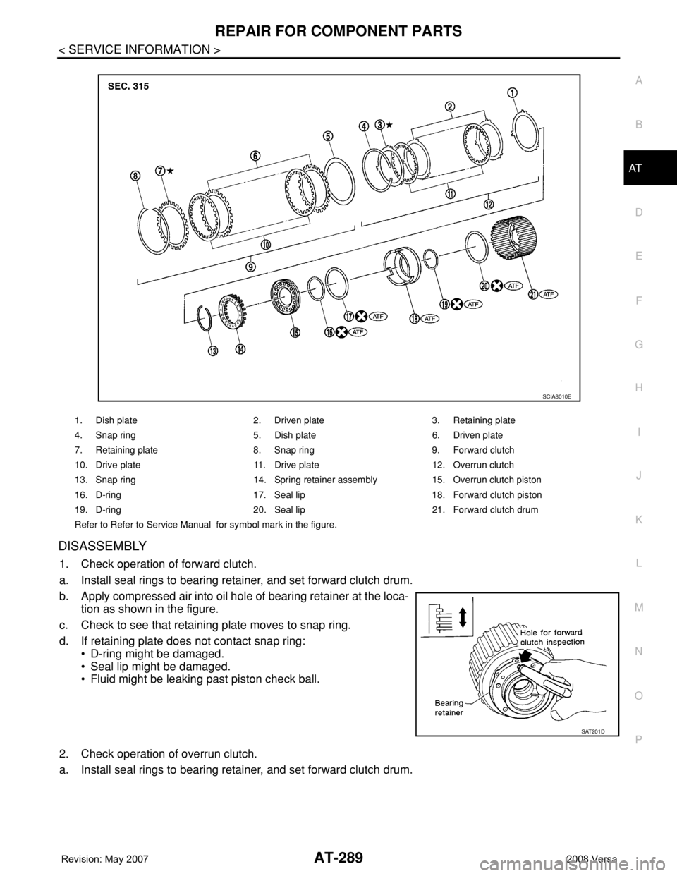
1. Check operation of forward clutch.
a. Install seal rings to bearing retainer, and set forward clutch drum.
b. Apply compressed air into oil hole of bearing retainer at the loca-
tion as shown in the figure.
c. Check to see that retaining plate moves to snap ring.
d. If retaining plate does not contact snap ring:
• D-ring might be damaged.
• Seal lip might be damaged.
• Fluid might be leaking past piston check ball.
2. Check operation of overrun clutch.
a. Install seal rings to bearing retainer, and set forward clutch drum.
1. Dish plate 2. Driven plate 3. Retaining plate
4. Snap ring 5. Dish plate 6. Driven plate
7. Retaining plate 8. Snap ring 9. Forward clutch
10. Drive plate 11. Drive plate 12. Overrun clutch
13. Snap ring 14. Spring retainer assembly 15. Overrun clutch piston
16. D-ring 17. Seal lip 18. Forward clutch piston
19. D-ring 20. Seal lip 21. Forward clutch drum
Refer to Refer to Service Manual for symbol mark in the figure.
SCIA8010E
SAT201D
Page 302 of 2771

AT-290
< SERVICE INFORMATION >
REPAIR FOR COMPONENT PARTS
b. Apply compressed air into oil hole of bearing retainer at the loca-
tion as shown in the figure.
c. Check to see that retaining plate moves to snap ring.
d. If retaining plate does not contact snap ring:
• D-ring might be damaged.
• Seal lip might be damaged.
• Fluid might be leaking past piston check ball.
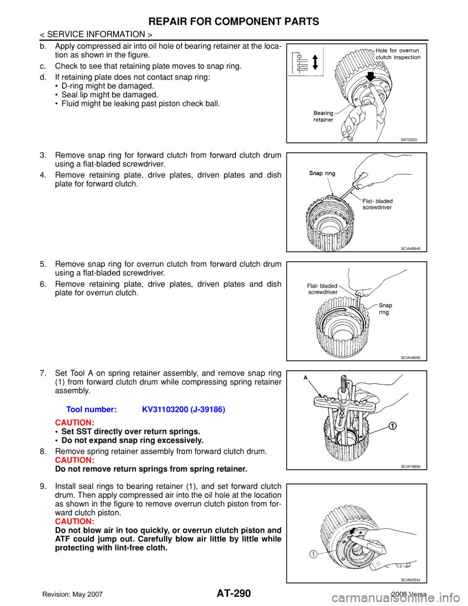
3. Remove snap ring for forward clutch from forward clutch drum
using a flat-bladed screwdriver.
4. Remove retaining plate, drive plates, driven plates and dish
plate for forward clutch.
5. Remove snap ring for overrun clutch from forward clutch drum
using a flat-bladed screwdriver.
6. Remove retaining plate, drive plates, driven plates and dish
plate for overrun clutch.
7. Set Tool A on spring retainer assembly, and remove snap ring
(1) from forward clutch drum while compressing spring retainer
assembly.
CAUTION:
• Set SST directly over return springs.
• Do not expand snap ring excessively.
8. Remove spring retainer assembly from forward clutch drum.
CAUTION:
Do not remove return springs from spring retainer.
9. Install seal rings to bearing retainer (1), and set forward clutch
drum. Then apply compressed air into the oil hole at the location
as shown in the figure to remove overrun clutch piston from for-
ward clutch piston.
CAUTION:
Do not blow air in too quickly, or overrun clutch piston and
ATF could jump out. Carefully blow air little by little while
protecting with lint-free cloth.
SAT202D
SCIA4894E
SCIA4895E
Tool number: KV31103200 (J-39186)
SCIA7989E
SCIA6004J
Page 303 of 2771

REPAIR FOR COMPONENT PARTS
AT-291
< SERVICE INFORMATION >
D
E
F
G
H
I
J
K
L
MA
B
AT
N
O
P
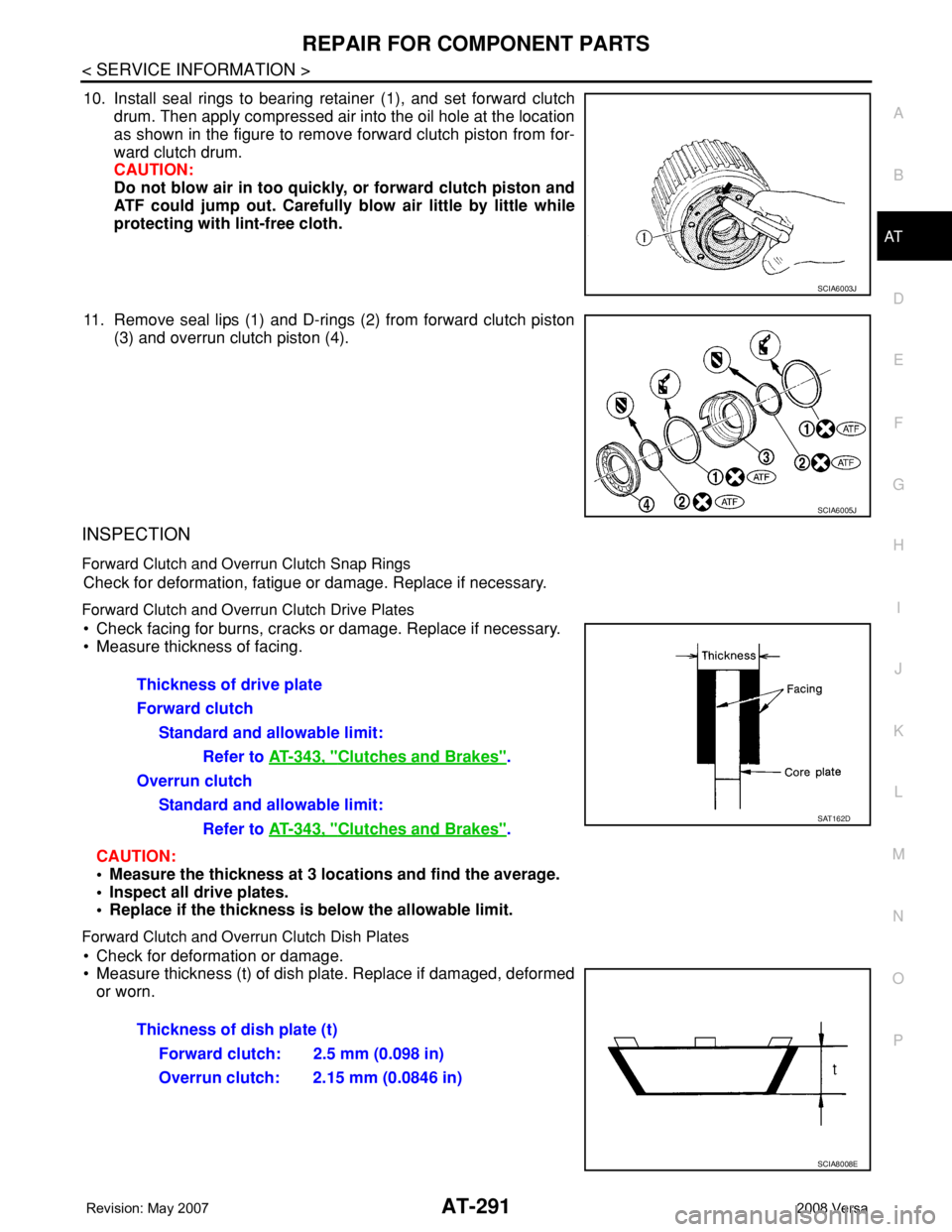
10. Install seal rings to bearing retainer (1), and set forward clutch
drum. Then apply compressed air into the oil hole at the location
as shown in the figure to remove forward clutch piston from for-
ward clutch drum.
CAUTION:
Do not blow air in too quickly, or forward clutch piston and
ATF could jump out. Carefully blow air little by little while
protecting with lint-free cloth.
11. Remove seal lips (1) and D-rings (2) from forward clutch piston
(3) and overrun clutch piston (4).
INSPECTION
Forward Clutch and Overrun Clutch Snap Rings
Check for deformation, fatigue or damage. Replace if necessary.
Forward Clutch and Overrun Clutch Drive Plates
• Check facing for burns, cracks or damage. Replace if necessary.
• Measure thickness of facing.
CAUTION:
• Measure the thickness at 3 locations and find the average.
• Inspect all drive plates.
• Replace if the thickness is below the allowable limit.
Forward Clutch and Overrun Clutch Dish Plates
• Check for deformation or damage.
• Measure thickness (t) of dish plate. Replace if damaged, deformed
or worn.
SCIA6003J
SCIA6005J
Thickness of drive plate
Forward clutch
Standard and allowable limit:
Refer to AT-343, "
Clutches and Brakes".
Overrun clutch
Standard and allowable limit:
Refer to AT-343, "
Clutches and Brakes".SAT162D
Thickness of dish plate (t)
Forward clutch: 2.5 mm (0.098 in)
Overrun clutch: 2.15 mm (0.0846 in)
SCIA8008E
Page 312 of 2771
AT-300
< SERVICE INFORMATION >
REPAIR FOR COMPONENT PARTS
DISASSEMBLY
1. Remove forward clutch hub from rear internal gear.
2. Remove end bearing (1) from rear internal gear (2).
3. Remove thrust washer from rear internal gear.
4. Remove end bearing (2) from forward one-way clutch (3).
(1): Forward clutch hub
1. End bearing 2. Forward clutch hub 3. Thrust washer
4. Rear internal gear 5. Forward one-way clutch
Refer to GI section to make sure icons (symbol marks) in the figure. Refer to GI-8, "
Component".
SAT251D
SCIA7028E
SCIA3691E
SCIA7026E
Page 313 of 2771
REPAIR FOR COMPONENT PARTS
AT-301
< SERVICE INFORMATION >
D
E
F
G
H
I
J
K
L
MA
B
AT
N
O
P
5. Remove forward one-way clutch from forward clutch hub.
INSPECTION
Rear Internal Gear and Forward Clutch Hub
Check rubbing surfaces for wear or damage. Replace if necessary.
(1): Rear internal gear
(2): Forward clutch hub
End Bearings and Forward One-way Clutch
• Check end bearings (1) for deformation and damage. Replace if
necessary.
• Check forward one-way clutch (2) for wear and damage. Replace if
necessary.
ASSEMBLY
1. Install forward one-way clutch on forward clutch hub.
CAUTION:
Be careful with the direction of forward one-way clutch.
SAT255D
SCIA5881J
SCIA7027E
SAT976H
Page 314 of 2771
AT-302
< SERVICE INFORMATION >
REPAIR FOR COMPONENT PARTS
2. Install end bearing (2) on forward one-way clutch (3).
(1): Forward clutch hub
3. Install thrust washer on rear internal gear.
CAUTION:
Align pawls of thrust washer with holes of rear internal
gear.
4. Install end bearing (1) on rear internal gear (2).
5. Install forward clutch hub on rear internal gear.
CAUTION:
• Check operation of forward one-way clutch.
Hold rear internal gear and turn forward clutch hub.
Check forward clutch hub for correct locking and unlock-
ing directions.
• If not as shown in figure, check the installation direction
of forward one-way clutch.
Output Shaft, Output Gear, Idler Gear, Reduction Pinion Gear and Bearing Retainer
INFOID:0000000001703388
COMPONENTS
SCIA7026E
SCIA3690E
SCIA7028E
AAT426