2008 NISSAN TIIDA MANUAL TRANSAXLE
[x] Cancel search: MANUAL TRANSAXLEPage 1 of 2771

-1
QUICK REFERENCE INDEX
AGENERAL INFORMATIONGIGeneral Information
BENGINEEMEngine Mechanical
LUEngine Lubrication System
COEngine Cooling System
ECEngine Control System
FLFuel System
EXExhaust System
ACCAccelerator Control System
CTRANSMISSION/
TRANSAXLECLClutch System
MTManual Transaxle
ATAutomatic Transaxle
CVTCVT
DDRIVELINE/AXLEFAXFront Axle
RAXRear Axle
ESUSPENSIONFSUFront Suspension
RSURear Suspension
WTRoad Wheels & Tires
FBRAKESBRBrake System
PBParking Brake System
BRCBrake Control System
GSTEERINGPSPower Steering System
STCSteering Control System
HRESTRAINTSSBSeat Belts
SRSSupplemental Restraint System (SRS)
IBODYBLBody, Lock & Security System
GWGlasses, Window System & Mirrors
RFRoof
EIExterior & Interior
IPInstrument Panel
SESeat
JAIR CONDITIONERMTCManual Air Conditioner
KELECTRICALSCStarting & Charging System
LTLighting System
DIDriver Information System
WWWiper, Washer & Horn
BCSBody Control System
LANLAN System
AVAudio Visual, Navigation & Telephone System
ACSAuto Cruise Control System
PGPower Supply, Ground & Circuit Elements
LMAINTENANCEMAMaintenance
Edition: May 2007
Revision: May 2007
Publication No. SM8E-1C11U0
B
D
© 2007 NISSAN NORTH AMERICA, INC.
All rights reserved. No part of this Service Manual may be reproduced or stored in a retrieval system, or transmitted in any
form, or by any means, electronic, mechanical, photo-copying, recording or otherwise, without the prior written permission
of Nissan North America Inc.
A
C
E
F
G
H
I
J
K
L
M
Page 7 of 2771

QUICK REFERENCE CHART: VERSA
2008
Fluids and LubricantsINFOID:0000000001903536
DescriptionCapacity (Approximate)
Liter US measure Imp measure
Fuel 52.0 13 3/4 gal 11 1/2 gal
Engine oil
Drain and refill With oil filter change 3.9 4 1/8 qt 3 3/8 qt
Without oil filter change 3.7 3 7/8 qt 3 1/4 qt
Dry engine (engine overhaul) 4.9 5 1/8 qt 4 3/8 qt
Cooling system
(with reservoir at max level) 6.8 7 1/4 qt 6 qt
Manual transaxle fluid (MTF) 2.0 4 1/4 pt 3 1/2 pt
Automatic transaxle fluid (ATF) 7.9 8 3/8 qt 7 qt
CVT fluid 8.3 8 3/4 qt 7 1/4 qt
Brake and clutch fluid — — —
Multi-purpose grease — — —
Windshield washer fluid 4.5 4 3/4 qt 4 qt
Air conditioning system refrigerant 0.45 ± 0.05 kg 0.99 ± 0.11 lb 0.99 ± 0.11 lb
Air conditioning system oil Typ e 1
120 m4.1 fl oz 4.2 fl oz
Typ e 2 100 m3.4 fl oz 3.5 fl oz
Page 16 of 2771

AT-4
Diagnosis Procedure .............................................210
KEY INTERLOCK CABLE ...............................213
Removal and Installation .......................................213
ON-VEHICLE SERVICE ..................................216
Control Valve Assembly and Accumulators ...........216
Park/Neutral Position (PNP) Switch ......................219
Revolution Sensor .................................................221
Turbine Revolution Sensor (Power Train Revolu-
tion Sensor) ...........................................................
222
Differential Side Oil Seal ........................................223
AIR BREATHER HOSE ...................................225
Removal and Installation .......................................225
TRANSAXLE ASSEMBLY ..............................226
Removal and Installation .......................................226
OVERHAUL .....................................................230
Component ............................................................230
Oil Channel ............................................................237
Location of Adjusting Shims, Needle Bearings and
Thrust Washers .....................................................
238
Location of Snap Rings .........................................239
DISASSEMBLY ...............................................240
Disassembly ..........................................................240
REPAIR FOR COMPONENT PARTS ..............257
Manual Shaft .........................................................257
Oil Pump ................................................................260
Control Valve Assembly ........................................263
Control Valve Upper Body .....................................272
Control Valve Lower Body .....................................276
Reverse Clutch ......................................................279
High Clutch ............................................................284
Forward and Overrun Clutches .............................288
Low & Reverse Brake ............................................295
Rear Internal Gear and Forward Clutch Hub .........299
Output Shaft, Output Gear, Idler Gear, Reduction
Pinion Gear and Bearing Retainer .........................
302
Band Servo Piston Assembly ................................307
Final Drive .............................................................313
ASSEMBLY ......................................................318
Assembly (1) .........................................................318
Adjustment (1) .......................................................319
Assembly (2) .........................................................325
Adjustment (2) .......................................................330
Assembly (3) .........................................................333
SERVICE DATA AND SPECIFICATIONS
(SDS) ................................................................
341
General Specification ............................................341
Vehicle Speed at Which Gear Shifting Occurs .....341
Vehicle Speed at When Lock-up Occurs/Releases
.
341
Stall Speed ............................................................341
Line Pressure ........................................................341
Adjusting shims, Needle Bearings, Thrust Wash-
ers and Snap Rings ..............................................
341
Control Valves .......................................................343
Accumulator ..........................................................343
Clutches and Brakes .............................................343
Final Drive .............................................................345
Planetary Carrier ...................................................345
Oil Pump ...............................................................345
Input Shaft .............................................................345
Reduction Pinion Gear ..........................................345
Band Servo ...........................................................345
Output Shaft ..........................................................346
Bearing Retainer ...................................................346
Total End Play .......................................................346
Reverse Clutch End Play ......................................346
Removal and Installation .......................................346
Shift Solenoid Valves ............................................346
Solenoid Valves ....................................................346
A/T Fluid Temperature Sensor ..............................347
Revolution Sensor .................................................347
Dropping Resistor .................................................347
Turbine Revolution Sensor (Power Train Revolu-
tion Sensor) ...........................................................
347
Page 26 of 2771
AT-14
< SERVICE INFORMATION >
PREPARATION
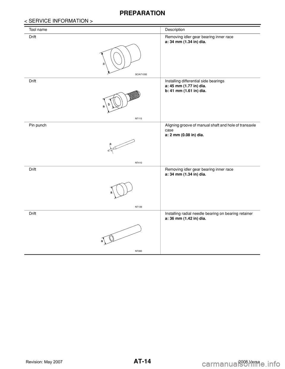
DriftRemoving idler gear bearing inner race
a: 34 mm (1.34 in) dia.
DriftInstalling differential side bearings
a: 45 mm (1.77 in) dia.
b: 41 mm (1.61 in) dia.
Pin punch Aligning groove of manual shaft and hole of transaxle
case
a: 2 mm (0.08 in) dia.
DriftRemoving idler gear bearing inner race
a: 34 mm (1.34 in) dia.
DriftInstalling radial needle bearing on bearing retainer
a: 36 mm (1.42 in) dia. Tool name Description
SCIA7105E
NT115
NT410
NT109
NT083
Page 219 of 2771

SHIFT CONTROL SYSTEM
AT-207
< SERVICE INFORMATION >
D
E
F
G
H
I
J
K
L
MA
B
AT
N
O
P
1. Place the selector lever knob (1) in “N” position.
2. Slide knob cover (2) downward.
3. Pull out lock pin (3) from selector lever knob (1).
4. Remove selector lever knob (1) and knob cover (2) as a set from
selector lever.
CAUTION:
Do not push selector button.
INSTALLATION
1. Insert lock pin (1) to selector lever knob (2).
2. Install knob cover (3) to selector lever knob (2).
3. Place the selector lever in “N” position.
4. Install selector lever knob over selector lever until a click is felt.
CAUTION:
• Do not tilt selector lever knob when installing. Install it
straight, and do not tap or apply any shock to install it.
• Do not push selector button.
Adjustment of A/T PositionINFOID:0000000001703359
Move selector lever from “P” position to “1” position. You should be able to feel the detents in each position. If
the detents cannot be felt or if the position indicator is improperly aligned, the control cable needs adjustment.
CAUTION:
Make sure that parking brake is applied before adjustment.
1. Remove the air duct assembly. Refer to EM-16
.
2. Remove the control cable nut (A) and control cable (1) and
place the manual lever (2) in the "P' position.
3. Place selector lever in “P” position.
4. Hold control cable (1) at the end and pull it with a force of 9.8 N
(approximately 1 kg, 2.2 lb). Release the control cable and tem-
porarily tighten control cable nut (A).
5. Tighten control cable nut (A) to the specified torque.
CAUTION:
Secure manual lever when tightening nut.
6. Move selector lever from “P” to “1” position again. Make sure that selector lever moves smoothly.
7. Check A/T position. Refer to AT-207, "
Checking of A/T Position".
8. Install air duct assembly. Refer to EM-16
.
Checking of A/T PositionINFOID:0000000001703360
1. Place selector lever in “P” position, and turn ignition switch ON (Do not start engine).
2. Make sure selector lever can be shifted to other than “P” position when brake pedal is depressed. Also
make sure selector lever can be shifted from “P” position only when brake pedal is depressed.
3. Move selector lever and check for excessive effort, sticking, noise or rattle.
4. Confirm selector lever stops at each position with the feel of engagement when it is moved through all the
positions. Check whether or not the actual position selector lever is in matches the position shown by the
shift position indicator and the transaxle.
SCIA6971E
SCIA6972E
Control cable nut : Refer to AT-203, "Control De-
vice Removal and Installation".WCIA0635E
Page 229 of 2771
ON-VEHICLE SERVICE
AT-217
< SERVICE INFORMATION >
D
E
F
G
H
I
J
K
L
MA
B
AT
N
O
P
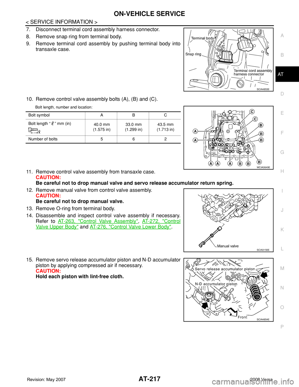
7. Disconnect terminal cord assembly harness connector.
8. Remove snap ring from terminal body.
9. Remove terminal cord assembly by pushing terminal body into
transaxle case.
10. Remove control valve assembly bolts (A), (B) and (C).
Bolt length, number and location:
11. Remove control valve assembly from transaxle case.
CAUTION:
Be careful not to drop manual valve and servo release accumulator return spring.
12. Remove manual valve from control valve assembly.
CAUTION:
Be careful not to drop manual valve.
13. Remove O-ring from terminal body.
14. Disassemble and inspect control valve assembly if necessary.
Refer to AT-263, "
Control Valve Assembly", AT-272, "Control
Valve Upper Body" and AT-276, "Control Valve Lower Body".
15. Remove servo release accumulator piston and N-D accumulator
piston by applying compressed air if necessary.
CAUTION:
Hold each piston with lint-free cloth.
SCIA4853E
Bolt symbol A B C
Bolt length “ ” mm (in)
40.0 mm
(1.575 in)33.0 mm
(1.299 in)43.5 mm
(1.713 in)
Number of bolts 5 6 2
WCIA0649E
SCIA3150E
SCIA4854E
Page 230 of 2771
AT-218
< SERVICE INFORMATION >
ON-VEHICLE SERVICE
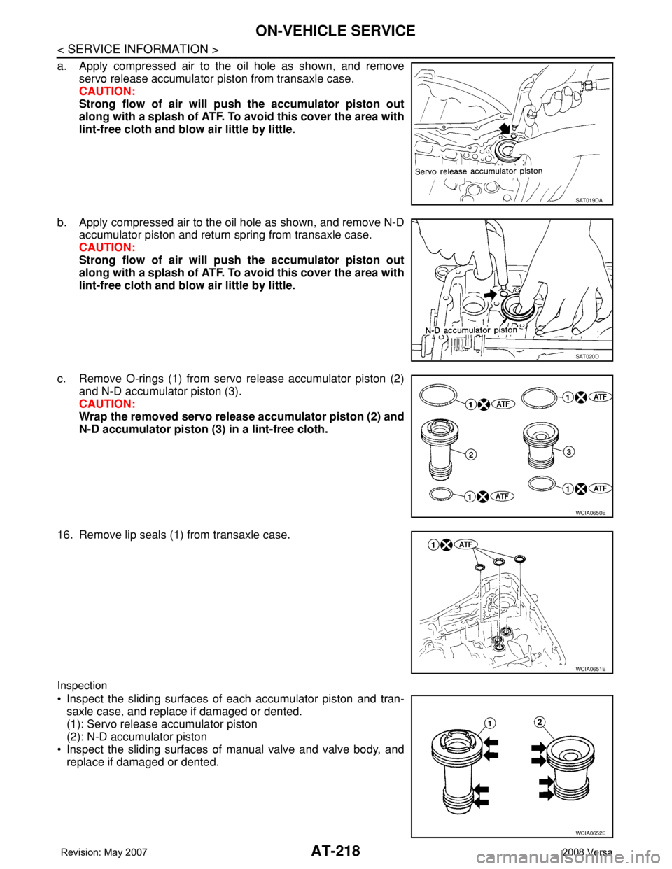
a. Apply compressed air to the oil hole as shown, and remove
servo release accumulator piston from transaxle case.
CAUTION:
Strong flow of air will push the accumulator piston out
along with a splash of ATF. To avoid this cover the area with
lint-free cloth and blow air little by little.
b. Apply compressed air to the oil hole as shown, and remove N-D
accumulator piston and return spring from transaxle case.
CAUTION:
Strong flow of air will push the accumulator piston out
along with a splash of ATF. To avoid this cover the area with
lint-free cloth and blow air little by little.
c. Remove O-rings (1) from servo release accumulator piston (2)
and N-D accumulator piston (3).
CAUTION:
Wrap the removed servo release accumulator piston (2) and
N-D accumulator piston (3) in a lint-free cloth.
16. Remove lip seals (1) from transaxle case.
Inspection
• Inspect the sliding surfaces of each accumulator piston and tran-
saxle case, and replace if damaged or dented.
(1): Servo release accumulator piston
(2): N-D accumulator piston
• Inspect the sliding surfaces of manual valve and valve body, and
replace if damaged or dented.
SAT019DA
SAT020D
WCIA0650E
WCIA0651E
WCIA0652E
Page 231 of 2771
ON-VEHICLE SERVICE
AT-219
< SERVICE INFORMATION >
D
E
F
G
H
I
J
K
L
MA
B
AT
N
O
P
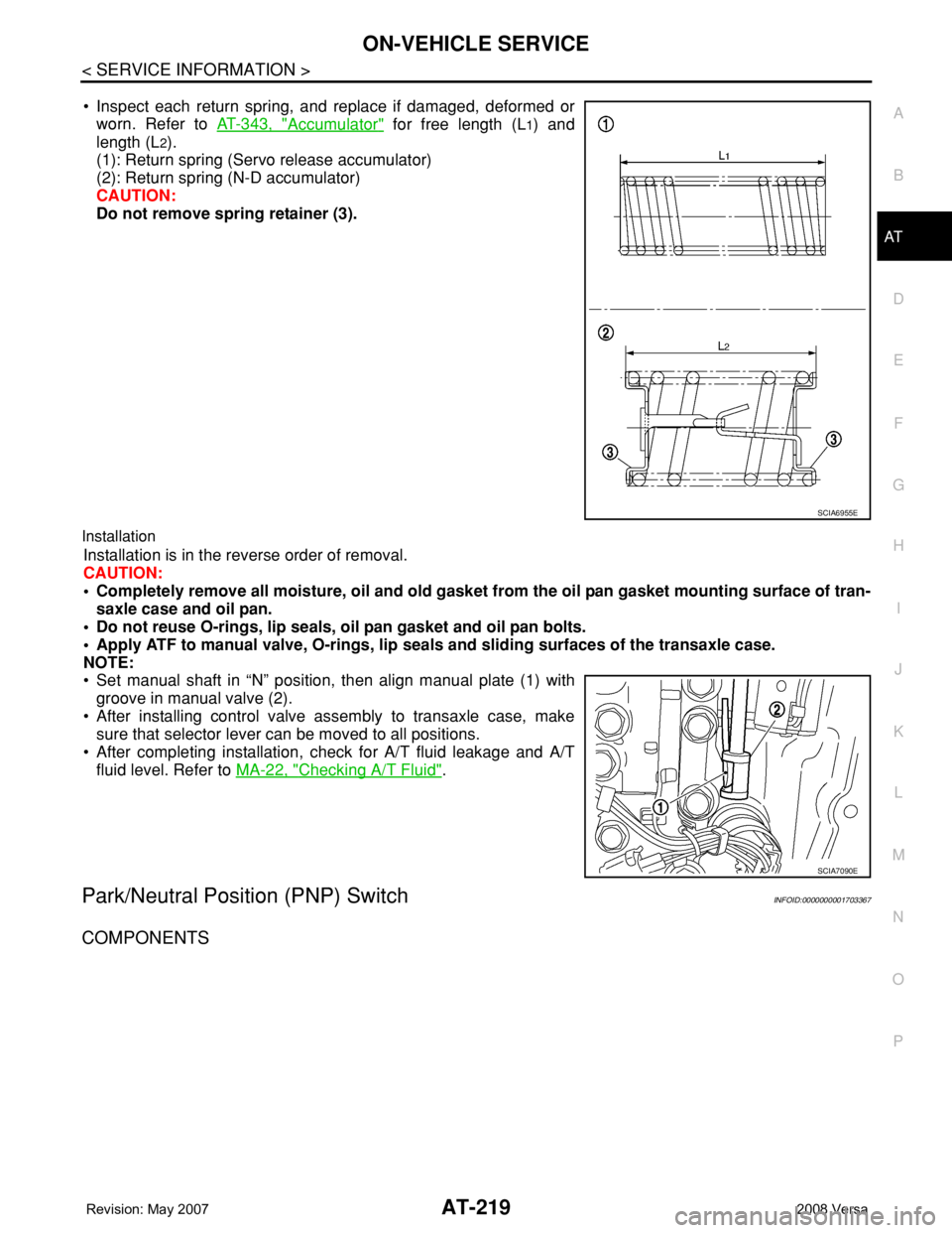
• Inspect each return spring, and replace if damaged, deformed or
worn. Refer to AT-343, "
Accumulator" for free length (L1) and
length (L
2).
(1): Return spring (Servo release accumulator)
(2): Return spring (N-D accumulator)
CAUTION:
Do not remove spring retainer (3).
Installation
Installation is in the reverse order of removal.
CAUTION:
• Completely remove all moisture, oil and old gasket from the oil pan gasket mounting surface of tran-
saxle case and oil pan.
• Do not reuse O-rings, lip seals, oil pan gasket and oil pan bolts.
• Apply ATF to manual valve, O-rings, lip seals and sliding surfaces of the transaxle case.
NOTE:
• Set manual shaft in “N” position, then align manual plate (1) with
groove in manual valve (2).
• After installing control valve assembly to transaxle case, make
sure that selector lever can be moved to all positions.
• After completing installation, check for A/T fluid leakage and A/T
fluid level. Refer to MA-22, "
Checking A/T Fluid".
Park/Neutral Position (PNP) SwitchINFOID:0000000001703367
COMPONENTS
SCIA6955E
SCIA7090E