2008 NISSAN TIIDA B1033
[x] Cancel search: B1033Page 1417 of 2771
DTC P0447 EVAP CANISTER VENT CONTROL VALVE
EC-343
< SERVICE INFORMATION >
C
D
E
F
G
H
I
J
K
L
MA
EC
N
P O
>>INSPECTION END
Component InspectionINFOID:0000000001702850
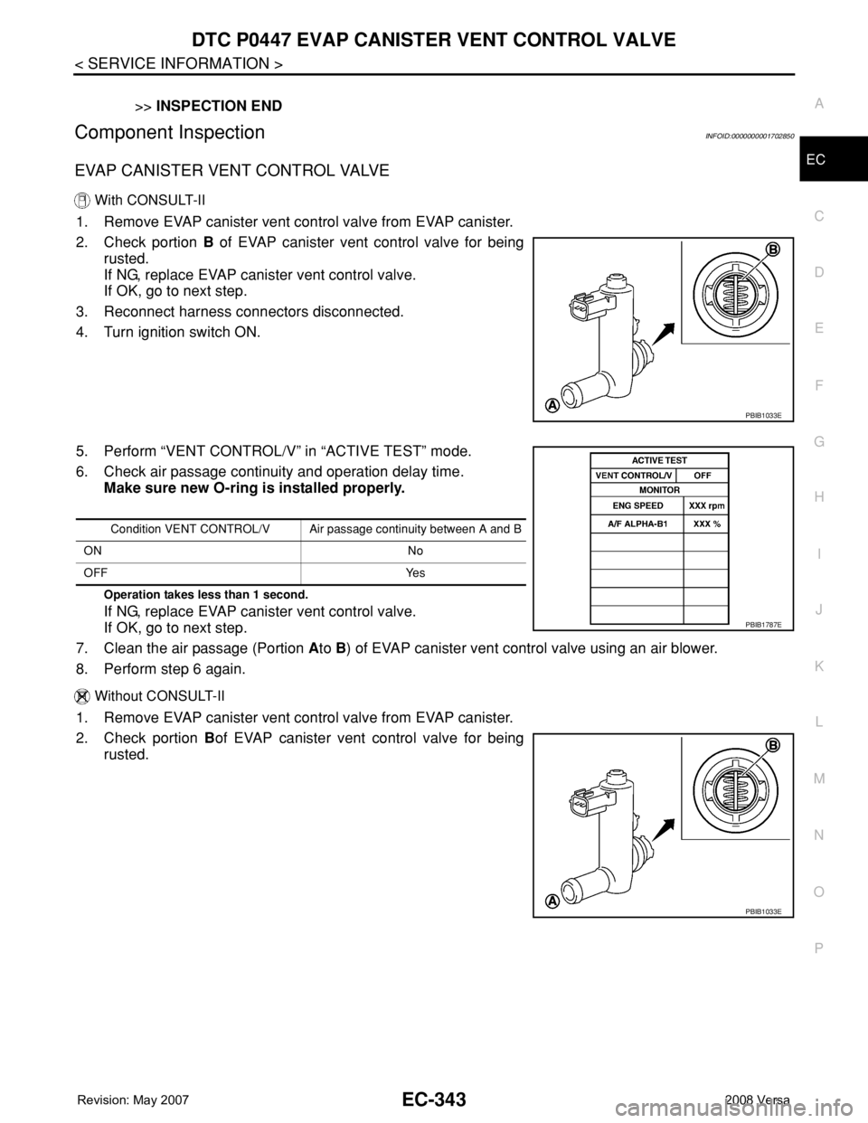
EVAP CANISTER VENT CONTROL VALVE
With CONSULT-II
1. Remove EVAP canister vent control valve from EVAP canister.
2. Check portion B of EVAP canister vent control valve for being
rusted.
If NG, replace EVAP canister vent control valve.
If OK, go to next step.
3. Reconnect harness connectors disconnected.
4. Turn ignition switch ON.
5. Perform “VENT CONTROL/V” in “ACTIVE TEST” mode.
6. Check air passage continuity and operation delay time.
Make sure new O-ring is installed properly.
Operation takes less than 1 second.
If NG, replace EVAP canister vent control valve.
If OK, go to next step.
7. Clean the air passage (Portion Ato B) of EVAP canister vent control valve using an air blower.
8. Perform step 6 again.
Without CONSULT-II
1. Remove EVAP canister vent control valve from EVAP canister.
2. Check portion Bof EVAP canister vent control valve for being
rusted.
PBIB1033E
Condition VENT CONTROL/V Air passage continuity between A and B
ON No
OFF Yes
PBIB1787E
PBIB1033E
Page 1423 of 2771
DTC P0448 EVAP CANISTER VENT CONTROL VALVE
EC-349
< SERVICE INFORMATION >
C
D
E
F
G
H
I
J
K
L
MA
EC
N
P O
OK >> GO TO 6.
NG >> GO TO 5.
5.DETECT MALFUNCTIONING PART
Check the following.
• EVAP canister for damage
• EVAP hose between EVAP canister and vehicle frame for clogging or poor connection
>> Repair hose or replace EVAP canister.
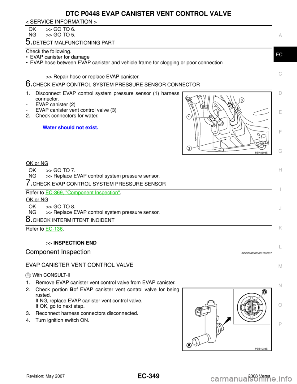
6.CHECK EVAP CONTROL SYSTEM PRESSURE SENSOR CONNECTOR
1. Disconnect EVAP control system pressure sensor (1) harness
connector.
- EVAP canister (2)
- EVAP canister vent control valve (3)
2. Check connectors for water.
OK or NG
OK >> GO TO 7.
NG >> Replace EVAP control system pressure sensor.
7.CHECK EVAP CONTROL SYSTEM PRESSURE SENSOR
Refer to EC-369, "
Component Inspection".
OK or NG
OK >> GO TO 8.
NG >> Replace EVAP control system pressure sensor.
8.CHECK INTERMITTENT INCIDENT
Refer to EC-136
.
>>INSPECTION END
Component InspectionINFOID:0000000001702857
EVAP CANISTER VENT CONTROL VALVE
With CONSULT-II
1. Remove EVAP canister vent control valve from EVAP canister.
2. Check portion Bof EVAP canister vent control valve for being
rusted.
If NG, replace EVAP canister vent control valve.
If OK, go to next step.
3. Reconnect harness connectors disconnected.
4. Turn ignition switch ON.Water should not exist.
BBIA0693E
PBIB1033E
Page 1424 of 2771
EC-350
< SERVICE INFORMATION >
DTC P0448 EVAP CANISTER VENT CONTROL VALVE
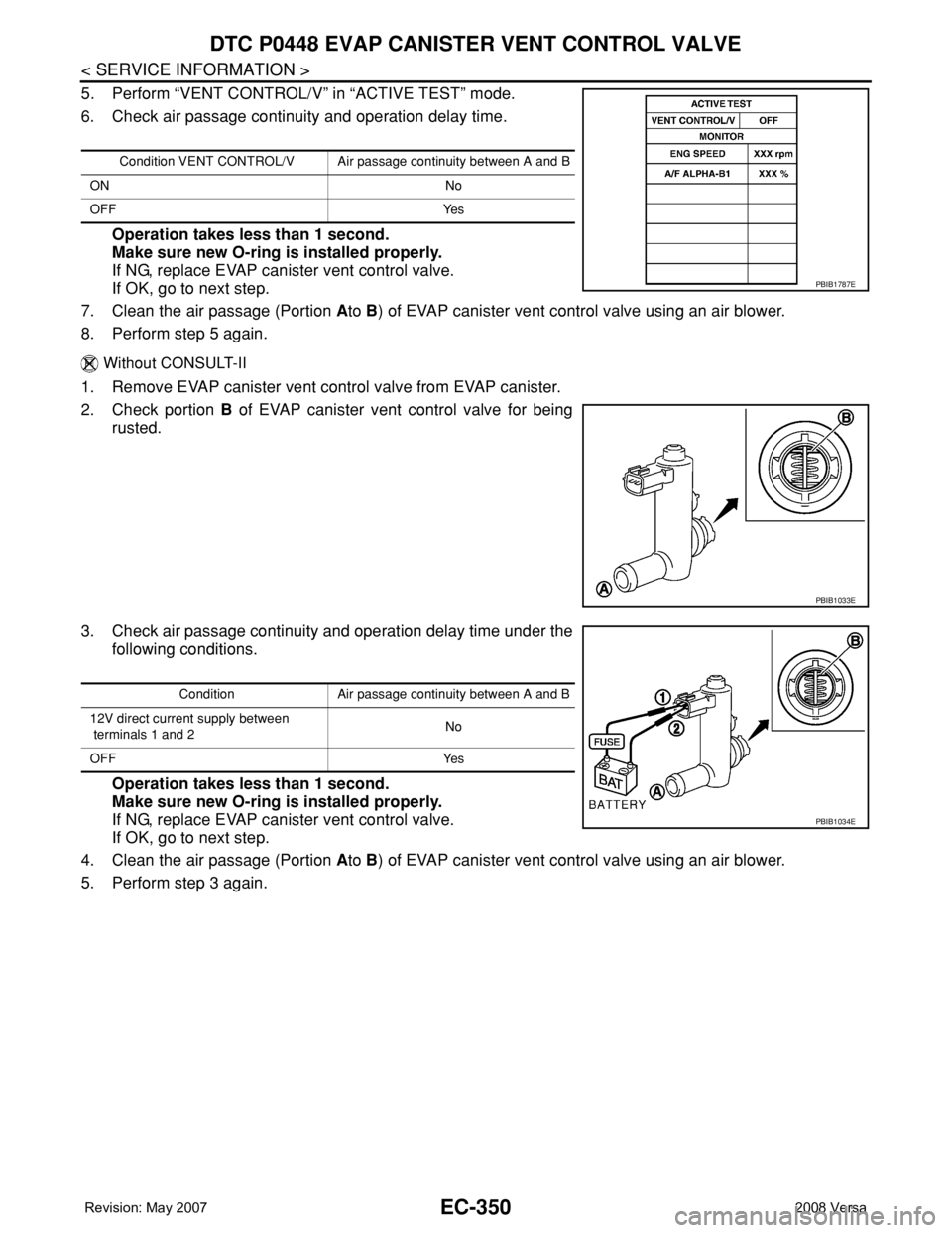
5. Perform “VENT CONTROL/V” in “ACTIVE TEST” mode.
6. Check air passage continuity and operation delay time.
Operation takes less than 1 second.
Make sure new O-ring is installed properly.
If NG, replace EVAP canister vent control valve.
If OK, go to next step.
7. Clean the air passage (Portion Ato B) of EVAP canister vent control valve using an air blower.
8. Perform step 5 again.
Without CONSULT-II
1. Remove EVAP canister vent control valve from EVAP canister.
2. Check portion B of EVAP canister vent control valve for being
rusted.
3. Check air passage continuity and operation delay time under the
following conditions.
Operation takes less than 1 second.
Make sure new O-ring is installed properly.
If NG, replace EVAP canister vent control valve.
If OK, go to next step.
4. Clean the air passage (Portion Ato B) of EVAP canister vent control valve using an air blower.
5. Perform step 3 again.
Condition VENT CONTROL/V Air passage continuity between A and B
ON No
OFF Yes
PBIB1787E
PBIB1033E
Condition Air passage continuity between A and B
12V direct current supply between
terminals 1 and 2No
OFF Yes
PBIB1034E
Page 2654 of 2771
SRS-20
< SYMPTOM DIAGNOSIS >
TROUBLE DIAGNOSIS
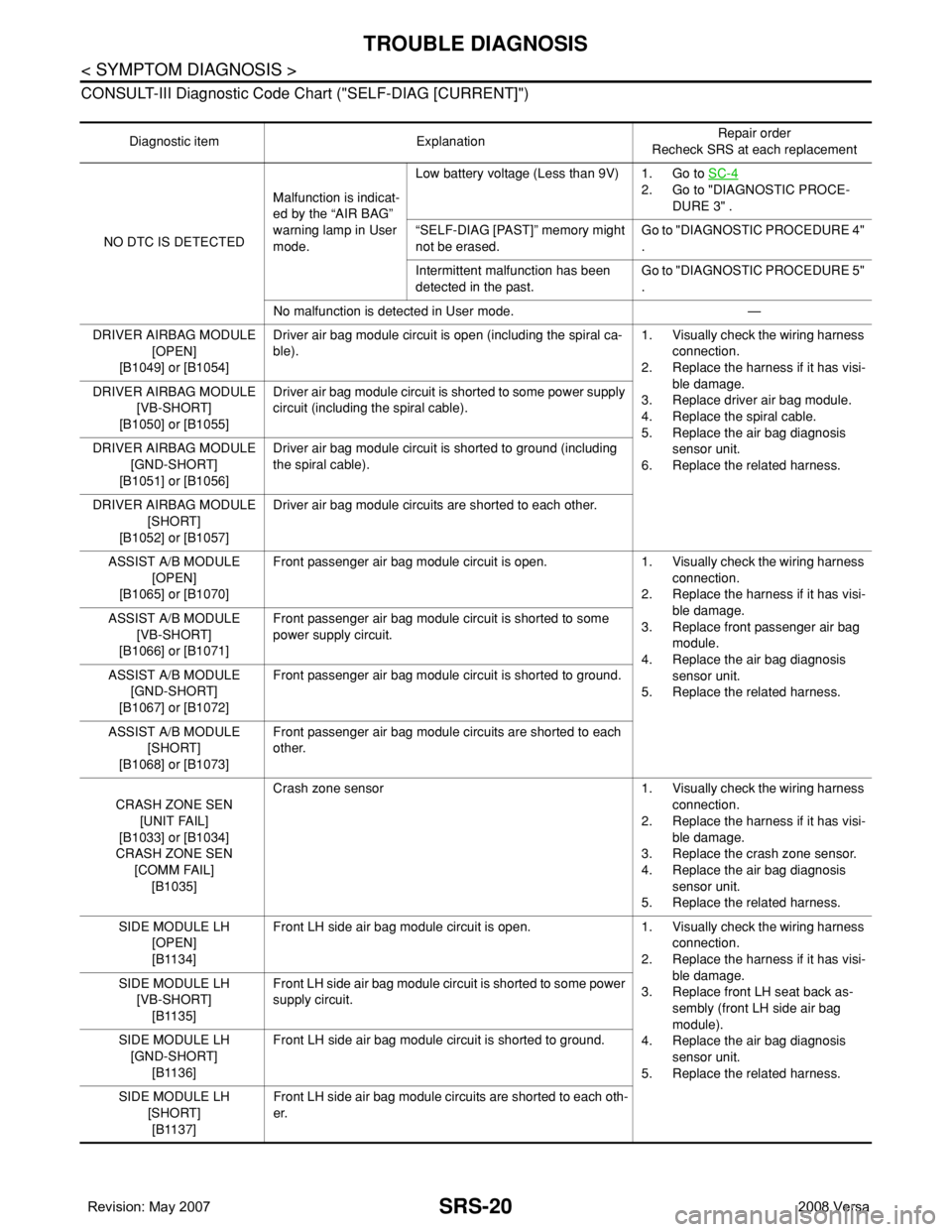
CONSULT-III Diagnostic Code Chart ("SELF-DIAG [CURRENT]")
Diagnostic item ExplanationRepair order
Recheck SRS at each replacement
NO DTC IS DETECTEDMalfunction is indicat-
ed by the “AIR BAG”
warning lamp in User
mode.Low battery voltage (Less than 9V) 1. Go to SC-4
2. Go to "DIAGNOSTIC PROCE-
DURE 3" .
“SELF-DIAG [PAST]” memory might
not be erased.Go to "DIAGNOSTIC PROCEDURE 4"
.
Intermittent malfunction has been
detected in the past.Go to "DIAGNOSTIC PROCEDURE 5"
.
No malfunction is detected in User mode. —
DRIVER AIRBAG MODULE
[OPEN]
[B1049] or [B1054]Driver air bag module circuit is open (including the spiral ca-
ble).1. Visually check the wiring harness
connection.
2. Replace the harness if it has visi-
ble damage.
3. Replace driver air bag module.
4. Replace the spiral cable.
5. Replace the air bag diagnosis
sensor unit.
6. Replace the related harness. DRIVER AIRBAG MODULE
[VB-SHORT]
[B1050] or [B1055]Driver air bag module circuit is shorted to some power supply
circuit (including the spiral cable).
DRIVER AIRBAG MODULE
[GND-SHORT]
[B1051] or [B1056]Driver air bag module circuit is shorted to ground (including
the spiral cable).
DRIVER AIRBAG MODULE
[SHORT]
[B1052] or [B1057]Driver air bag module circuits are shorted to each other.
ASSIST A/B MODULE
[OPEN]
[B1065] or [B1070]Front passenger air bag module circuit is open. 1. Visually check the wiring harness
connection.
2. Replace the harness if it has visi-
ble damage.
3. Replace front passenger air bag
module.
4. Replace the air bag diagnosis
sensor unit.
5. Replace the related harness. ASSIST A/B MODULE
[VB-SHORT]
[B1066] or [B1071]Front passenger air bag module circuit is shorted to some
power supply circuit.
ASSIST A/B MODULE
[GND-SHORT]
[B1067] or [B1072]Front passenger air bag module circuit is shorted to ground.
ASSIST A/B MODULE
[SHORT]
[B1068] or [B1073]Front passenger air bag module circuits are shorted to each
other.
CRASH ZONE SEN
[UNIT FAIL]
[B1033] or [B1034]
CRASH ZONE SEN
[COMM FAIL]
[B1035]Crash zone sensor 1. Visually check the wiring harness
connection.
2. Replace the harness if it has visi-
ble damage.
3. Replace the crash zone sensor.
4. Replace the air bag diagnosis
sensor unit.
5. Replace the related harness.
SIDE MODULE LH
[OPEN]
[B1134]Front LH side air bag module circuit is open. 1. Visually check the wiring harness
connection.
2. Replace the harness if it has visi-
ble damage.
3. Replace front LH seat back as-
sembly (front LH side air bag
module).
4. Replace the air bag diagnosis
sensor unit.
5. Replace the related harness. SIDE MODULE LH
[VB-SHORT]
[B1135]Front LH side air bag module circuit is shorted to some power
supply circuit.
SIDE MODULE LH
[GND-SHORT]
[B1136]Front LH side air bag module circuit is shorted to ground.
SIDE MODULE LH
[SHORT]
[B1137]Front LH side air bag module circuits are shorted to each oth-
er.
Page 2659 of 2771

TROUBLE DIAGNOSIS
SRS-25
< SYMPTOM DIAGNOSIS >
C
D
E
F
G
I
J
K
L
MA
B
SRS
N
O
P
CRASH ZONE SEN
[UNIT FAIL]
[B1033] or [B1034]
CRASH ZONE SEN
[COMM FAIL]
[B1035]Crash zone sensor 1. Visually check the wiring harness
connection.
2. Replace the harness if it has visi-
ble damage.
3. Replace the crash zone sensor.
4. Replace the air bag diagnosis
sensor unit.
5. Replace the related harness.
SIDE MODULE LH
[OPEN]
[B1134]Front LH side air bag module circuit is open. 1. Visually check the wiring harness
connection.
2. Replace the harness if it has visi-
ble damage.
3. Replace front LH seat back as-
sembly (front LH side air bag
module).
4. Replace the air bag diagnosis
sensor unit.
5. Replace the related harness. SIDE MODULE LH
[VB-SHORT]
[B1135]Front LH side air bag module circuit is shorted to some power
supply circuit.
SIDE MODULE LH
[GND-SHORT]
[B1136]Front LH side air bag module circuit is shorted to ground.
SIDE MODULE LH
[SHORT]
[B1137]Front LH side air bag module circuits are shorted to each oth-
er.
SIDE MODULE RH
[OPEN]
[B1129]Front RH side air bag module circuit is open. 1. Visually check the wiring harness
connection.
2. Replace the harness if it has visi-
ble damage.
3. Replace front RH seat back as-
sembly (front RH side air bag
module).
4. Replace the air bag diagnosis
sensor unit.
5. Replace the related harness. SIDE MODULE RH
[VB-SHORT]
[B1130]Front RH side air bag module circuit is shorted to some power
supply circuit.
SIDE MODULE RH
[GND-SHORT]
[B1131]Front RH side air bag module circuit is shorted to ground.
SIDE MODULE RH
[SHORT]
[B1132]Front RH side air bag module circuits are shorted to each oth-
er.
SATELLITE SENS LH
[UNIT FAIL]
[ B 111 8 ] o r [ B 111 9 ]
SATELLITE SENS LH
[COMM FAIL]
[B1120]LH side air bag (satellite) sensor 1. Visually check the wiring harness
connection.
2. Replace the harness if it has visi-
ble damage.
3. Replace the LH side air bag (sat-
ellite) sensor.
4. Replace the air bag diagnosis
sensor unit.
5. Replace the related harness.
SATELLITE SENS RH
[UNIT FAIL]
[ B 111 3 ] o r [ B 111 4 ]
SATELLITE SENS RH
[COMM FAIL]
[ B 111 5 ]RH side air bag (satellite) sensor 1. Visually check the wiring harness
connection.
2. Replace the harness if it has visi-
ble damage.
3. Replace the RH side air bag (sat-
ellite) sensor.
4. Replace the air bag diagnosis
sensor unit.
5. Replace the related harness. Diagnostic item ExplanationRepair order
Recheck SRS at each replacement