2008 NISSAN TIIDA Head unit
[x] Cancel search: Head unitPage 2452 of 2771
IPDM E/R (INTELLIGENT POWER DISTRIBUTION MODULE ENGINE ROOM)
PG-19
< SERVICE INFORMATION >
C
D
E
F
G
H
I
J
L
MA
B
PG
N
O
P
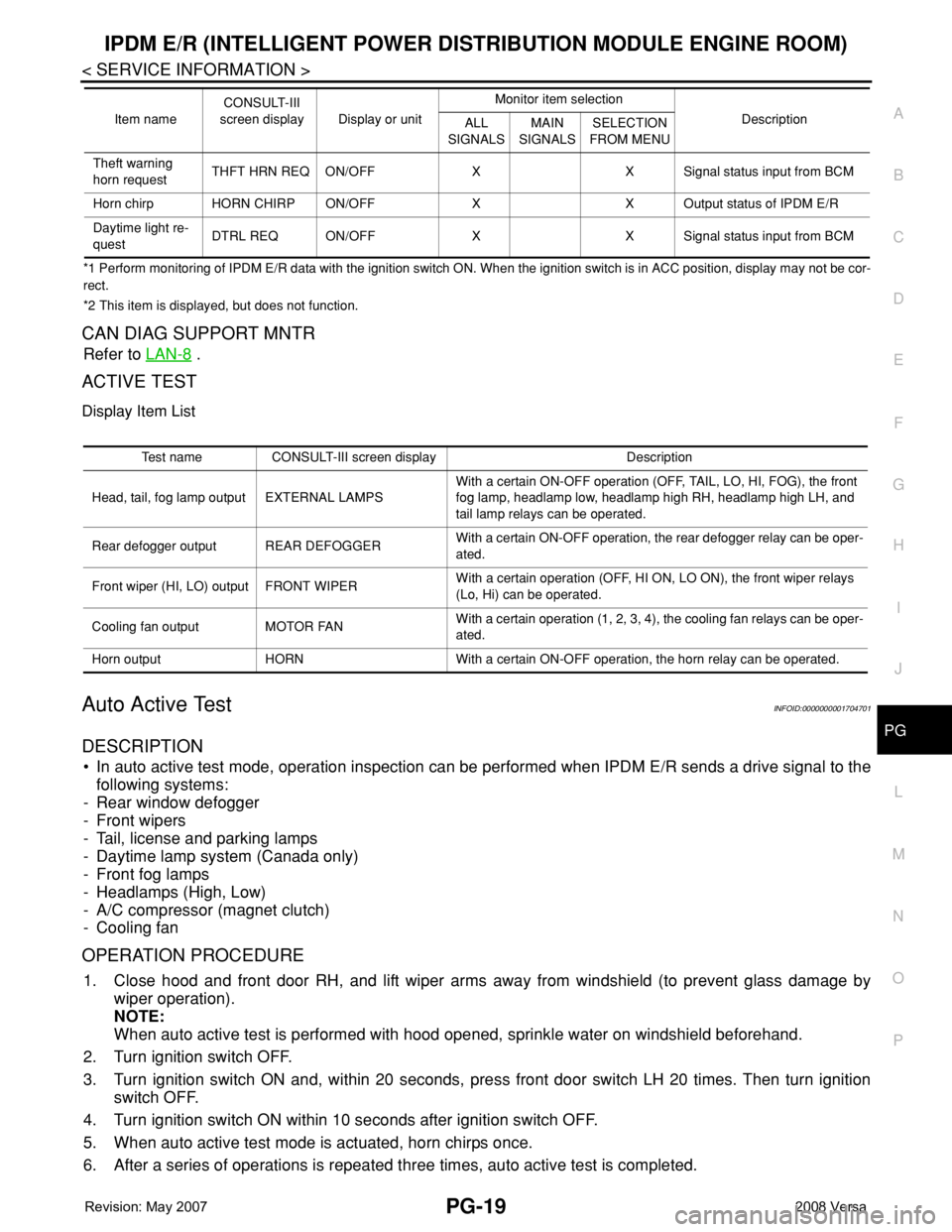
*1 Perform monitoring of IPDM E/R data with the ignition switch ON. When the ignition switch is in ACC position, display may not be cor-
rect.
*2 This item is displayed, but does not function.
CAN DIAG SUPPORT MNTR
Refer to LAN-8 .
ACTIVE TEST
Display Item List
Auto Active TestINFOID:0000000001704701
DESCRIPTION
• In auto active test mode, operation inspection can be performed when IPDM E/R sends a drive signal to the
following systems:
- Rear window defogger
- Front wipers
- Tail, license and parking lamps
- Daytime lamp system (Canada only)
- Front fog lamps
- Headlamps (High, Low)
- A/C compressor (magnet clutch)
- Cooling fan
OPERATION PROCEDURE
1. Close hood and front door RH, and lift wiper arms away from windshield (to prevent glass damage by
wiper operation).
NOTE:
When auto active test is performed with hood opened, sprinkle water on windshield beforehand.
2. Turn ignition switch OFF.
3. Turn ignition switch ON and, within 20 seconds, press front door switch LH 20 times. Then turn ignition
switch OFF.
4. Turn ignition switch ON within 10 seconds after ignition switch OFF.
5. When auto active test mode is actuated, horn chirps once.
6. After a series of operations is repeated three times, auto active test is completed.
Theft warning
horn requestTHFT HRN REQ ON/OFF X X Signal status input from BCM
Horn chirp HORN CHIRP ON/OFF X X Output status of IPDM E/R
Daytime light re-
questDTRL REQ ON/OFF X X Signal status input from BCM Item nameCONSULT-III
screen display Display or unitMonitor item selection
Description
ALL
SIGNALSMAIN
SIGNALSSELECTION
FROM MENU
Test name CONSULT-III screen display Description
Head, tail, fog lamp output EXTERNAL LAMPSWith a certain ON-OFF operation (OFF, TAIL, LO, HI, FOG), the front
fog lamp, headlamp low, headlamp high RH, headlamp high LH, and
tail lamp relays can be operated.
Rear defogger output REAR DEFOGGERWith a certain ON-OFF operation, the rear defogger relay can be oper-
ated.
Front wiper (HI, LO) output FRONT WIPERWith a certain operation (OFF, HI ON, LO ON), the front wiper relays
(Lo, Hi) can be operated.
Cooling fan output MOTOR FANWith a certain operation (1, 2, 3, 4), the cooling fan relays can be oper-
ated.
Horn output HORN With a certain ON-OFF operation, the horn relay can be operated.
Page 2515 of 2771
STEERING COLUMN
PS-9
< SERVICE INFORMATION >
C
D
E
F
H
I
J
K
L
MA
B
PS
N
O
P
STEERING COLUMN
Removal and InstallationINFOID:0000000001703861
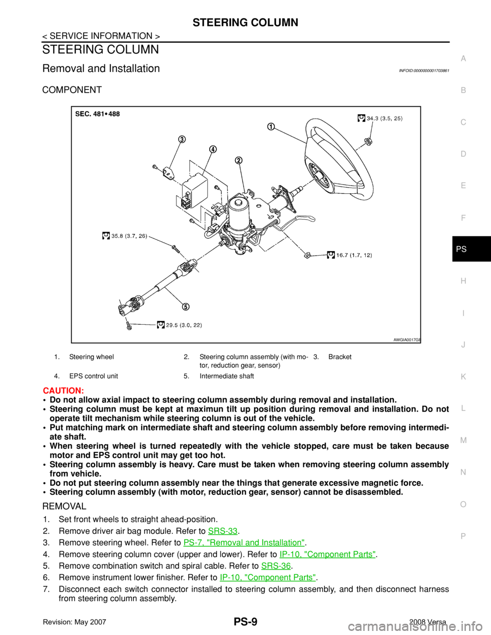
COMPONENT
CAUTION:
• Do not allow axial impact to steering column assembly during removal and installation.
• Steering column must be kept at maximun tilt up position during removal and installation. Do not
operate tilt mechanism while steering column is out of the vehicle.
• Put matching mark on intermediate shaft and steering column assembly before removing intermedi-
ate shaft.
• When steering wheel is turned repeatedly with the vehicle stopped, care must be taken because
motor and EPS control unit may get too hot.
• Steering column assembly is heavy. Care must be taken when removing steering column assembly
from vehicle.
• Do not put steering column assembly near the things that generate excessive magnetic force.
• Steering column assembly (with motor, reduction gear, sensor) cannot be disassembled.
REMOVAL
1. Set front wheels to straight ahead-position.
2. Remove driver air bag module. Refer to SRS-33
.
3. Remove steering wheel. Refer to PS-7, "
Removal and Installation".
4. Remove steering column cover (upper and lower). Refer to IP-10, "
Component Parts".
5. Remove combination switch and spiral cable. Refer to SRS-36
.
6. Remove instrument lower finisher. Refer to IP-10, "
Component Parts".
7. Disconnect each switch connector installed to steering column assembly, and then disconnect harness
from steering column assembly.
1. Steering wheel 2. Steering column assembly (with mo-
tor, reduction gear, sensor)3. Bracket
4. EPS control unit 5. Intermediate shaft
AWGIA0017GB
Page 2553 of 2771
SUNROOF
RF-23
< ON-VEHICLE REPAIR >
C
D
E
F
G
H
J
K
L
MA
B
RF
N
O
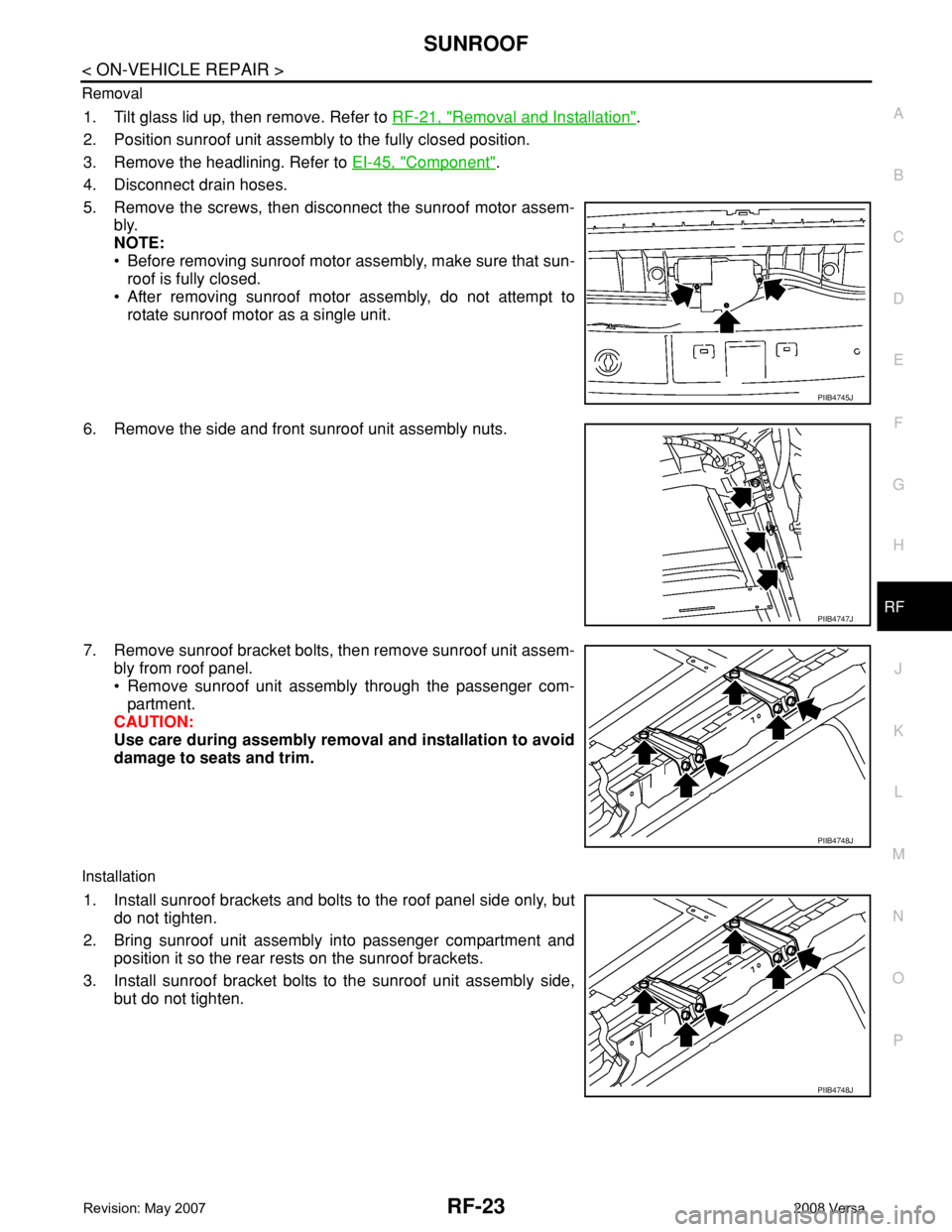
P Removal
1. Tilt glass lid up, then remove. Refer to RF-21, "Removal and Installation".
2. Position sunroof unit assembly to the fully closed position.
3. Remove the headlining. Refer to EI-45, "
Component".
4. Disconnect drain hoses.
5. Remove the screws, then disconnect the sunroof motor assem-
bly.
NOTE:
• Before removing sunroof motor assembly, make sure that sun-
roof is fully closed.
• After removing sunroof motor assembly, do not attempt to
rotate sunroof motor as a single unit.
6. Remove the side and front sunroof unit assembly nuts.
7. Remove sunroof bracket bolts, then remove sunroof unit assem-
bly from roof panel.
• Remove sunroof unit assembly through the passenger com-
partment.
CAUTION:
Use care during assembly removal and installation to avoid
damage to seats and trim.
Installation
1. Install sunroof brackets and bolts to the roof panel side only, but
do not tighten.
2. Bring sunroof unit assembly into passenger compartment and
position it so the rear rests on the sunroof brackets.
3. Install sunroof bracket bolts to the sunroof unit assembly side,
but do not tighten.
PIIB4745J
PIIB4747J
PIIB4748J
PIIB4748J
Page 2554 of 2771
RF-24
< ON-VEHICLE REPAIR >
SUNROOF
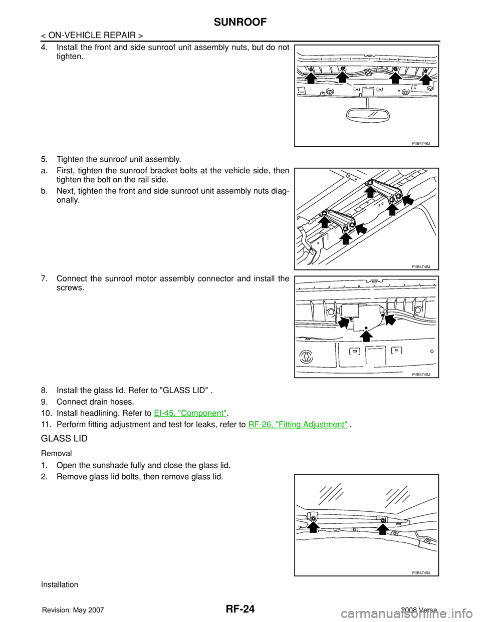
4. Install the front and side sunroof unit assembly nuts, but do not
tighten.
5. Tighten the sunroof unit assembly.
a. First, tighten the sunroof bracket bolts at the vehicle side, then
tighten the bolt on the rail side.
b. Next, tighten the front and side sunroof unit assembly nuts diag-
onally.
6.7. Connect the sunroof motor assembly connector and install the
screws.
8. Install the glass lid. Refer to "GLASS LID" .
9. Connect drain hoses.
10. Install headlining. Refer to EI-45, "
Component".
11. Perform fitting adjustment and test for leaks, refer to RF-26, "
Fitting Adjustment" .
GLASS LID
Removal
1. Open the sunshade fully and close the glass lid.
2. Remove glass lid bolts, then remove glass lid.
Installation
PIIB4746J
PIIB4748J
PIIB4745J
PIIB4749J
Page 2555 of 2771
SUNROOF
RF-25
< ON-VEHICLE REPAIR >
C
D
E
F
G
H
J
K
L
MA
B
RF
N
O
P
1. Position the glass lid on sunroof unit assembly.
2. Partially install glass lid bolts. Tighten left front bolt first, then right rear to prevent uneven torque while
tightening remaining bolts.
3. After installation, check sunroof operation and glass lid assembly alignment. Refer to RF-26, "
Fitting
Adjustment" .
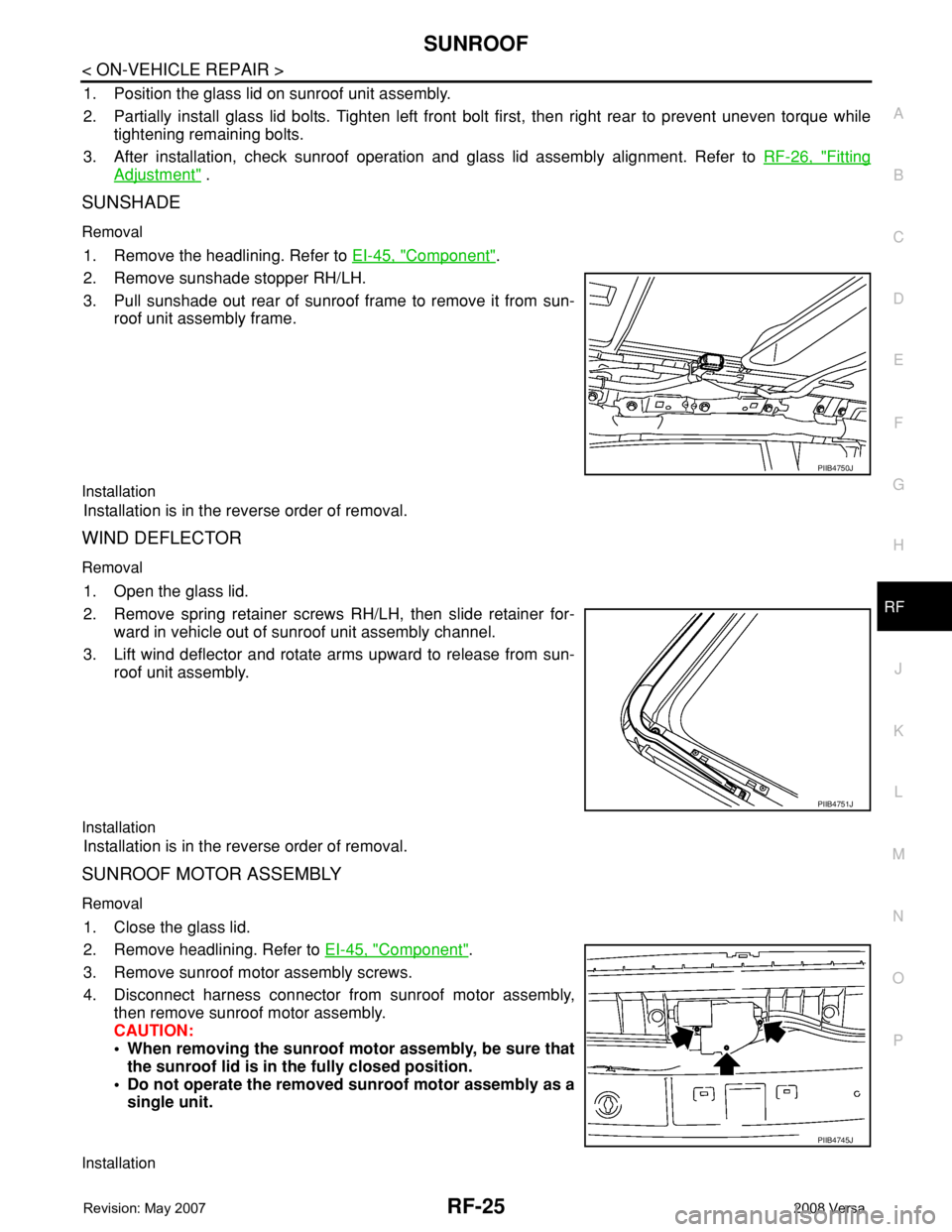
SUNSHADE
Removal
1. Remove the headlining. Refer to EI-45, "Component".
2. Remove sunshade stopper RH/LH.
3. Pull sunshade out rear of sunroof frame to remove it from sun-
roof unit assembly frame.
Installation
Installation is in the reverse order of removal.
WIND DEFLECTOR
Removal
1. Open the glass lid.
2. Remove spring retainer screws RH/LH, then slide retainer for-
ward in vehicle out of sunroof unit assembly channel.
3. Lift wind deflector and rotate arms upward to release from sun-
roof unit assembly.
Installation
Installation is in the reverse order of removal.
SUNROOF MOTOR ASSEMBLY
Removal
1. Close the glass lid.
2. Remove headlining. Refer to EI-45, "
Component".
3. Remove sunroof motor assembly screws.
4. Disconnect harness connector from sunroof motor assembly,
then remove sunroof motor assembly.
CAUTION:
• When removing the sunroof motor assembly, be sure that
the sunroof lid is in the fully closed position.
• Do not operate the removed sunroof motor assembly as a
single unit.
Installation
PIIB4750J
PIIB4751J
PIIB4745J
Page 2559 of 2771
SUNROOF
RF-29
< ON-VEHICLE REPAIR >
C
D
E
F
G
H
J
K
L
MA
B
RF
N
O
P
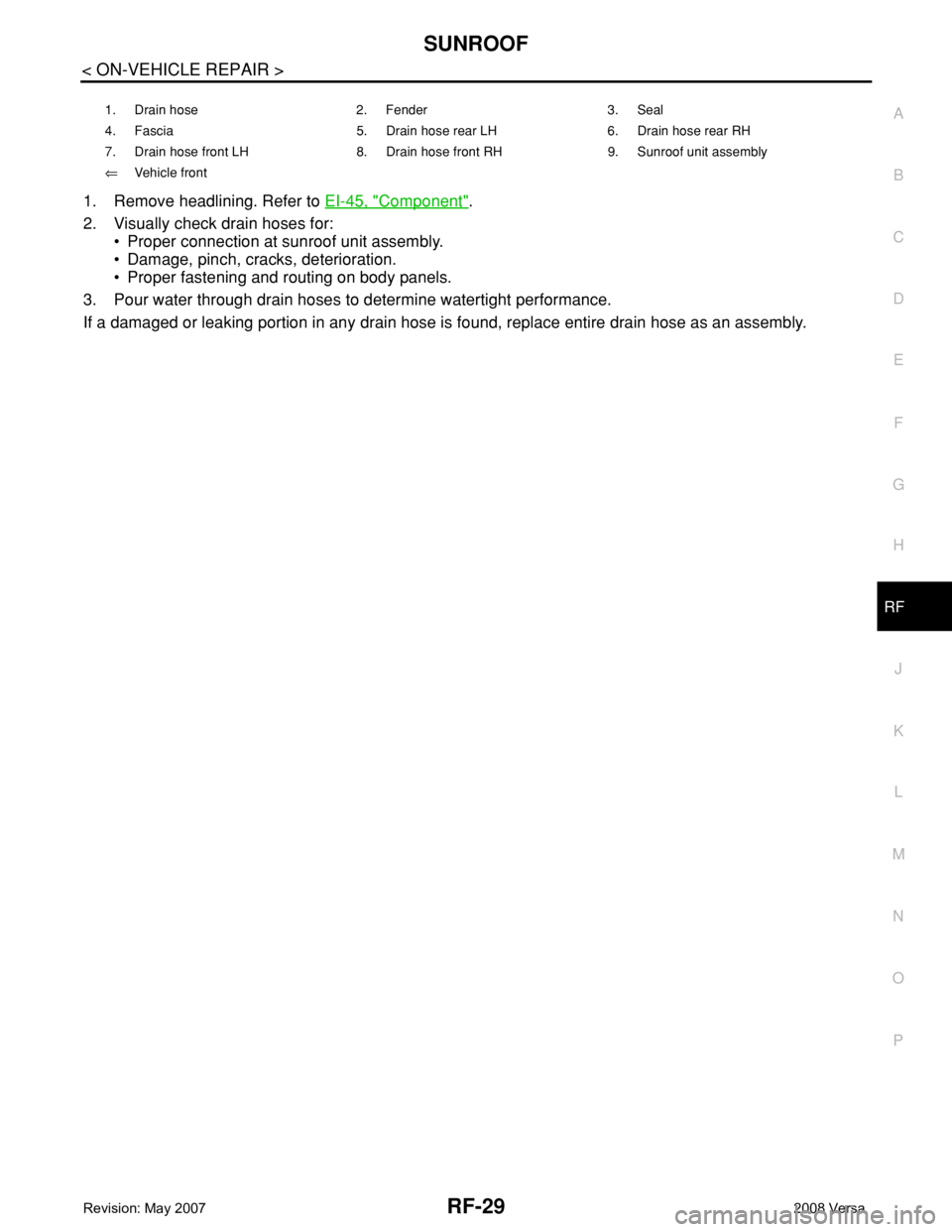
1. Remove headlining. Refer to EI-45, "Component".
2. Visually check drain hoses for:
• Proper connection at sunroof unit assembly.
• Damage, pinch, cracks, deterioration.
• Proper fastening and routing on body panels.
3. Pour water through drain hoses to determine watertight performance.
If a damaged or leaking portion in any drain hose is found, replace entire drain hose as an assembly.
1. Drain hose 2. Fender 3. Seal
4. Fascia 5. Drain hose rear LH 6. Drain hose rear RH
7. Drain hose front LH 8. Drain hose front RH 9. Sunroof unit assembly
⇐Vehicle front
Page 2564 of 2771
REAR SUSPENSION ASSEMBLY
RSU-5
< SERVICE INFORMATION >
C
D
F
G
H
I
J
K
L
MA
B
RSU
N
O
P
REAR SUSPENSION ASSEMBLY
On-Vehicle Inspection and ServiceINFOID:0000000001703736
Make sure the mounting conditions (looseness, backlash) of each component and component conditions
(wear, damage) are within specifications.
SHOCK ABSORBER INSPECTION
Check shock absorber for oil leakage, damage and replace it if necessary.
Wheel AlignmentInspectionINFOID:0000000001703737
DESCRIPTION
Measure wheel alignment under unladen conditions.
NOTE:
“Unladen conditions” means that fuel, engine coolant, and lubricant are full. Spare tire, jack, hand tools and
mats are in designated positions.
PRELIMINARY
Check the following:
1. Tires for improper air pressure and wear.
2. Road wheels for runout. Refer to WT-5
.
3. Wheel bearing axial end play. Refer to RAX-4, "
On-Vehicle Inspection and Service" .
4. Shock absorber operation.
5. Each mounting part of suspension for looseness and deformation.
6. Rear suspension beam for cracks, deformation, and other damage.
7. Vehicle height (posture).
GENERAL INFORMATION AND RECOMMENDATIONS
1. A Four-Wheel Thrust Alignment should be performed.
• This type of alignment is recommended for any NISSAN vehicle.
• The four-wheel “thrust” process helps ensure that the vehicle is properly aligned and the steering wheel
is centered.
• The alignment machine itself should be capable of accepting any NISSAN vehicle.
• The alignment machine should be checked to ensure that it is level.
2. Make sure the alignment machine is properly calibrated.
• Your alignment machine should be regularly calibrated in order to give correct information.
• Check with the manufacturer of your specific alignment machine for their recommended Service/Cali-
bration Schedule.
THE ALIGNMENT PROCESS
IMPORTANT: Use only the alignment specifications listed in this Service Manual. Refer to RSU-12, "Wheel
Alignment (Unladen*)" .
1. When displaying the alignment settings, many alignment machines use “indicators”: (Green/red, plus or
minus, Go/No Go). Do NOT use these indicators.
• The alignment specifications programmed into your alignment machine that operate these indicators
may not be correct.
• This may result in an ERROR.
2. Some newer alignment machines are equipped with an optional “Rolling Compensation” method to “com-
pensate” the sensors (alignment targets or head units). Do NOT use this “Rolling Compensation”
method.
• Use the “Jacking Compensation” method. After installing the alignment targets or head units, raise the
vehicle and rotate the wheels 1/2 turn both ways.
• See Instructions in the alignment machine you are using for more information.
CAMBER INSPECTION