2008 NISSAN TIIDA Head unit
[x] Cancel search: Head unitPage 2003 of 2771
![NISSAN TIIDA 2008 Service Repair Manual LAN-12
< FUNCTION DIAGNOSIS >[CAN FUNDAMENTAL]
TROUBLE DIAGNOSIS
CAN Diagnosis with CONSULT-III
INFOID:0000000001711207
CAN diagnosis on CONSULT-III extracts the root cause by receiving the following NISSAN TIIDA 2008 Service Repair Manual LAN-12
< FUNCTION DIAGNOSIS >[CAN FUNDAMENTAL]
TROUBLE DIAGNOSIS
CAN Diagnosis with CONSULT-III
INFOID:0000000001711207
CAN diagnosis on CONSULT-III extracts the root cause by receiving the following](/manual-img/5/57399/w960_57399-2002.png)
LAN-12
< FUNCTION DIAGNOSIS >[CAN FUNDAMENTAL]
TROUBLE DIAGNOSIS
CAN Diagnosis with CONSULT-III
INFOID:0000000001711207
CAN diagnosis on CONSULT-III extracts the root cause by receiving the following information.
• Response to the system call
• Control unit diagnosis information
• Self-diagnosis
• CAN diagnostic support monitor
Self-DiagnosisINFOID:0000000001711208
CAN Diagnostic Support MonitorINFOID:0000000001711209
MONITOR ITEM (CONSULT-III)
Unit name Symptom
ECM• Engine torque limiting is affected, and shift harshness increases.
• Engine speed drops.
BCM• Reverse warning chime does not sound.
• The front wiper moves under continuous operation mode even though the front
wiper switch being in the intermittent position.
• The room lamp does not turn ON.
• The engine does not start (if an error or malfunction occurs while turning the igni-
tion switch OFF.)
• The steering lock does not release (if an error or malfunction occurs while turning
the ignition switch OFF.)
EPS control unit The steering effort increases.
Combination meter• The tachometer and the speedometer do not move.
• Warning lamps turn ON.
• Indicator lamps do not turn ON.
ABS actuator and electric unit (control unit) Normal operation.
TCM No impact on operation.
IPDM E/RWhen the ignition switch is ON,
• The headlamps (Lo) turn ON.
• The cooling fan continues to rotate.
DTCSelf-diagnosis item
(CONSULT-III indication)DTC detection condition Inspection/Action
U1000 CAN COMM CIRCUITWhen ECM is not transmitting or receiving CAN
communication signal of OBD (emission-related
diagnosis) for 2 seconds or more.
Start the inspection. Re-
fer to the applicable sec-
tion of the indicated
control unit. When a control unit (except for ECM) is not
transmitting or receiving CAN communication
signal for 2 seconds or more.
U1001 CAN COMM CIRCUITWhen ECM is not transmitting or receiving CAN
communication signal other than OBD (emis-
sion-related diagnosis) for 2 seconds or more.
U1002 SYSTEM COMMWhen a control unit is not transmitting or receiv-
ing CAN communication signal for 2 seconds or
less.
U1010 CONTROL UNIT [CAN]When an error is detected during the initial diag-
nosis for CAN controller of each control unit.Replace the control unit
indicating “U1010”.
Page 2141 of 2771
LT-4
< SERVICE INFORMATION >
HEADLAMP (FOR USA)
HEADLAMP (FOR USA)
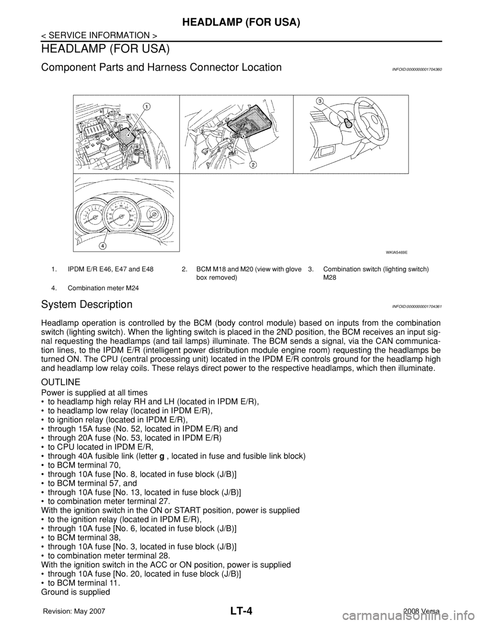
Component Parts and Harness Connector LocationINFOID:0000000001704360
System DescriptionINFOID:0000000001704361
Headlamp operation is controlled by the BCM (body control module) based on inputs from the combination
switch (lighting switch). When the lighting switch is placed in the 2ND position, the BCM receives an input sig-
nal requesting the headlamps (and tail lamps) illuminate. The BCM sends a signal, via the CAN communica-
tion lines, to the IPDM E/R (intelligent power distribution module engine room) requesting the headlamps be
turned ON. The CPU (central processing unit) located in the IPDM E/R controls ground for the headlamp high
and headlamp low relay coils. These relays direct power to the respective headlamps, which then illuminate.
OUTLINE
Power is supplied at all times
• to headlamp high relay RH and LH (located in IPDM E/R),
• to headlamp low relay (located in IPDM E/R),
• to ignition relay (located in IPDM E/R),
• through 15A fuse (No. 52, located in IPDM E/R) and
• through 20A fuse (No. 53, located in IPDM E/R)
• to CPU located in IPDM E/R,
• through 40A fusible link (letter g , located in fuse and fusible link block)
• to BCM terminal 70,
• through 10A fuse [No. 8, located in fuse block (J/B)]
• to BCM terminal 57, and
• through 10A fuse [No. 13, located in fuse block (J/B)]
• to combination meter terminal 27.
With the ignition switch in the ON or START position, power is supplied
• to the ignition relay (located in IPDM E/R),
• through 10A fuse [No. 6, located in fuse block (J/B)]
• to BCM terminal 38,
• through 10A fuse [No. 3, located in fuse block (J/B)]
• to combination meter terminal 28.
With the ignition switch in the ACC or ON position, power is supplied
• through 10A fuse [No. 20, located in fuse block (J/B)]
• to BCM terminal 11.
Ground is supplied
1. IPDM E/R E46, E47 and E48 2. BCM M18 and M20 (view with glove
box removed)3. Combination switch (lighting switch)
M28
4. Combination meter M24
WKIA5469E
Page 2150 of 2771
HEADLAMP (FOR USA)
LT-13
< SERVICE INFORMATION >
C
D
E
F
G
H
I
J
L
MA
B
LT
N
O
P
NOTE:
Perform monitoring of IPDM E/R data with the ignition switch ON. When the ignition switch is at ACC, the dis-
play may not be correct.
ACTIVE TEST
Headlamp High Beam Does Not Illuminate (Both Sides)INFOID:0000000001704371
1.CHECK COMBINATION SWITCH INPUT SIGNAL
With CONSULT-III
1. Select “BCM” on CONSULT-III. Select “HEAD LAMP” on “SELECT TEST ITEM” screen.
2. Select “DATA MONITOR” on “SELECT DIAG MODE” screen. Make sure that “HI BEAM SW” turns ON-
OFF linked with operation of lighting switch.
Without CONSULT-III
Refer to LT-63, "
Combination Switch Inspection" .
OK or NG
OK >> GO TO 2.
NG >> Check combination switch (lighting switch). Refer to LT-63, "
Combination Switch Inspection" .
2.HEADLAMP ACTIVE TEST
With CONSULT-III
1. Select “IPDM E/R” on CONSULT-III. Select “ACTIVE TEST” on “SELECT DIAG MODE” screen.
2. Select “EXTERNAL LAMPS” on “SELECT TEST ITEM” screen.
3. Touch “HI” screen.
4. Make sure headlamp high beam operates.
Without CONSULT-III
1. Start auto active test. Refer to PG-19, "
Auto Active Test" .
2. Make sure headlamp high beam operates.
Item nameCONSULT-III screen
displayDisplay or
unitMonitor item selection
Description
ALL
SIGNALSMAIN
SIGNALSSELECTION
FROM MENU
Parking, license plate
and tail lamps requestTAIL&CLR REQ ON/OFF×× ×Signal status input from BCM
Headlamp low beam re-
questHL LO REQ ON/OFF×× ×Signal status input from BCM
Headlamp high beam re-
questHL HI REQ ON/OFF×× ×Signal status input from BCM
Front fog lamps request FR FOG REQ ON/OFF×× ×Signal status input from BCM
Daytime light request DTRL REQ ON/OFF x x x Signal status input from BCM
Test item CONSULT-III screen display Description
Tail lamp relay output TAIL LAMPAllows tail lamp relay to operate by switching operation ON-OFF at your
option.
Headlamp relay (HI, LO) out-
put
LAMPSAllows headlamp relay (HI, LO) to operate by switching operation (OFF,
HI, LO) at your option (Head lamp high beam repeats ON-OFF every 1
second).
Front fog lamp relay (FOG)
outputAllows fog lamp relay (FOG) to operate by switching operation ON-OFF
at your option.
When lighting switch is high
position: HI BEAM SW ON
Headlamp high beam should operate
(Headlamp high beam repeats ON–OFF every 2 sec-
onds).
Page 2162 of 2771
HEADLAMP (FOR CANADA) - DAYTIME LIGHT SYSTEM -
LT-25
< SERVICE INFORMATION >
C
D
E
F
G
H
I
J
L
MA
B
LT
N
O
P
HEADLAMP (FOR CANADA) - DAYTIME LIGHT SYSTEM -
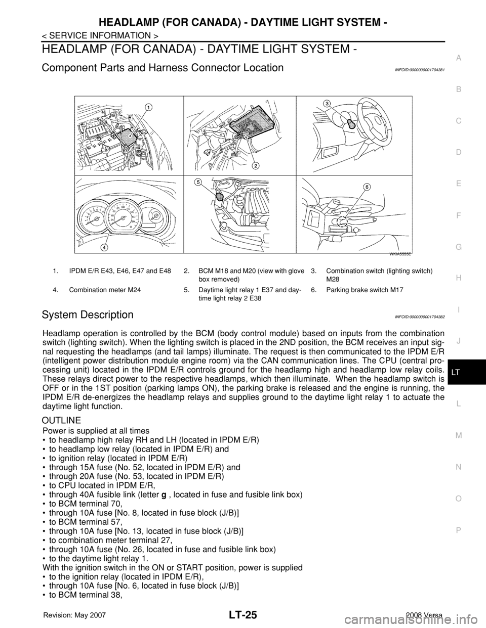
Component Parts and Harness Connector LocationINFOID:0000000001704381
System DescriptionINFOID:0000000001704382
Headlamp operation is controlled by the BCM (body control module) based on inputs from the combination
switch (lighting switch). When the lighting switch is placed in the 2ND position, the BCM receives an input sig-
nal requesting the headlamps (and tail lamps) illuminate. The request is then communicated to the IPDM E/R
(intelligent power distribution module engine room) via the CAN communication lines. The CPU (central pro-
cessing unit) located in the IPDM E/R controls ground for the headlamp high and headlamp low relay coils.
These relays direct power to the respective headlamps, which then illuminate. When the headlamp switch is
OFF or in the 1ST position (parking lamps ON), the parking brake is released and the engine is running, the
IPDM E/R de-energizes the headlamp relays and supplies ground to the daytime light relay 1 to actuate the
daytime light function.
OUTLINE
Power is supplied at all times
• to headlamp high relay RH and LH (located in IPDM E/R)
• to headlamp low relay (located in IPDM E/R) and
• to ignition relay (located in IPDM E/R)
• through 15A fuse (No. 52, located in IPDM E/R) and
• through 20A fuse (No. 53, located in IPDM E/R)
• to CPU located in IPDM E/R,
• through 40A fusible link (letter g , located in fuse and fusible link box)
• to BCM terminal 70,
• through 10A fuse [No. 8, located in fuse block (J/B)]
• to BCM terminal 57,
• through 10A fuse [No. 13, located in fuse block (J/B)]
• to combination meter terminal 27,
• through 10A fuse (No. 26, located in fuse and fusible link box)
• to the daytime light relay 1.
With the ignition switch in the ON or START position, power is supplied
• to the ignition relay (located in IPDM E/R),
• through 10A fuse [No. 6, located in fuse block (J/B)]
• to BCM terminal 38,
1. IPDM E/R E43, E46, E47 and E48 2. BCM M18 and M20 (view with glove
box removed)3. Combination switch (lighting switch)
M28
4. Combination meter M24 5. Daytime light relay 1 E37 and day-
time light relay 2 E386. Parking brake switch M17
WKIA5555E
Page 2176 of 2771
FRONT FOG LAMP
LT-39
< SERVICE INFORMATION >
C
D
E
F
G
H
I
J
L
MA
B
LT
N
O
P
FRONT FOG LAMP
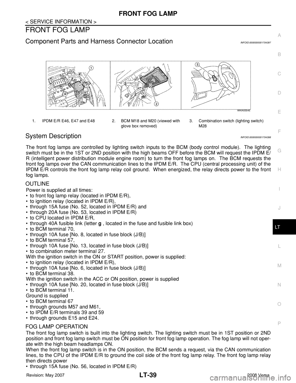
Component Parts and Harness Connector LocationINFOID:0000000001704397
System DescriptionINFOID:0000000001704398
The front fog lamps are controlled by lighting switch inputs to the BCM (body control module). The lighting
switch must be in the 1ST or 2ND position with the high beams OFF before the BCM will request the IPDM E/
R (intelligent power distribution module engine room) to turn the front fog lamps on. The BCM requests the
front fog lamps over the CAN communication lines to the IPDM E/R. The CPU (central processing unit) of the
IPDM E/R controls the front fog lamp relay coil ground. When energized, the relay directs power to the front
fog lamps.
OUTLINE
Power is supplied at all times:
• to front fog lamp relay (located in IPDM E/R),
• to ignition relay (located in IPDM E/R),
• through 15A fuse (No. 52, located in IPDM E/R) and
• through 20A fuse (No. 53, located in IPDM E/R)
• to CPU located in IPDM E/R,
• through 40A fusible link (letter g , located in the fuse and fusible link box)
• to BCM terminal 70,
• through 10A fuse [No. 8, located in fuse block (J/B)]
• to BCM terminal 57,
• through 10A fuse [No. 13, located in fuse block (J/B)]
• to combination meter terminal 27.
With the ignition switch in the ON or START position, power is supplied:
• to ignition relay (located in IPDM E/R),
• through 10A fuse [No. 6, located in fuse block (J/B)]
• to BCM terminal 38.
With the ignition switch in the ACC or ON position, power is supplied
• through 10A fuse [No. 20, located in fuse block (J/B)]
• to BCM terminal 11.
Ground is supplied
• to BCM terminal 67
• through grounds M57 and M61,
• to IPDM E/R terminals 39 and 59
• through grounds E15 and E24.
FOG LAMP OPERATION
The front fog lamp switch is built into the lighting switch. The lighting switch must be in 1ST position or 2ND
position and front fog lamp switch must be ON position for front fog lamp operation. The fog lamp will not oper-
ate with the high beam headlamps ON.
When the front fog lamp switch is in the ON position, the BCM sends a request, via the CAN communication
lines, to the CPU of the IPDM E/R to ground the coil side of the front fog lamp relay. The front fog lamp relay
then directs power
• through 15A fuse (No. 56, located in IPDM E/R)
1. IPDM E/R E46, E47 and E48 2. BCM M18 and M20 (viewed with
glove box removed)3. Combination switch (lighting switch)
M28
WKIA5554E
Page 2200 of 2771
COMBINATION SWITCH
LT-63
< SERVICE INFORMATION >
C
D
E
F
G
H
I
J
L
MA
B
LT
N
O
P
Terminal and Reference Value for BCMINFOID:0000000001704434
Refer to BCS-11, "Terminal and Reference Value for BCM" .
CONSULT-III Function (BCM)INFOID:0000000001704435
Refer to LT- 11 , "CONSULT-III Function (BCM)" .
Combination Switch InspectionINFOID:0000000001704436
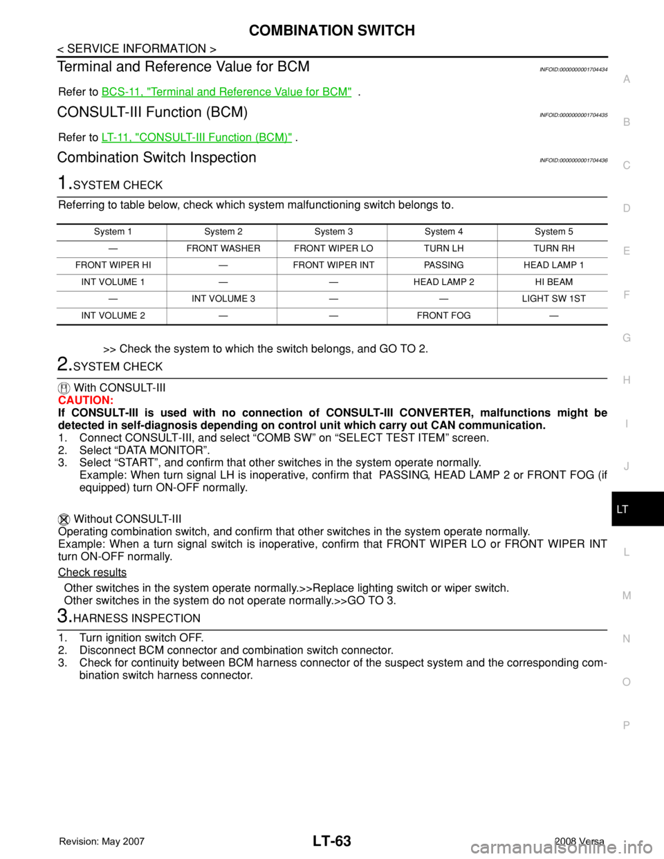
1.SYSTEM CHECK
Referring to table below, check which system malfunctioning switch belongs to.
>> Check the system to which the switch belongs, and GO TO 2.
2.SYSTEM CHECK
With CONSULT-III
CAUTION:
If CONSULT-III is used with no connection of CONSULT-III CONVERTER, malfunctions might be
detected in self-diagnosis depending on control unit which carry out CAN communication.
1. Connect CONSULT-III, and select “COMB SW” on “SELECT TEST ITEM” screen.
2. Select “DATA MONITOR”.
3. Select “START”, and confirm that other switches in the system operate normally.
Example: When turn signal LH is inoperative, confirm that PASSING, HEAD LAMP 2 or FRONT FOG (if
equipped) turn ON-OFF normally.
Without CONSULT-III
Operating combination switch, and confirm that other switches in the system operate normally.
Example: When a turn signal switch is inoperative, confirm that FRONT WIPER LO or FRONT WIPER INT
turn ON-OFF normally.
Check results
Other switches in the system operate normally.>>Replace lighting switch or wiper switch.
Other switches in the system do not operate normally.>>GO TO 3.
3.HARNESS INSPECTION
1. Turn ignition switch OFF.
2. Disconnect BCM connector and combination switch connector.
3. Check for continuity between BCM harness connector of the suspect system and the corresponding com-
bination switch harness connector.
System 1 System 2 System 3 System 4 System 5
— FRONT WASHER FRONT WIPER LO TURN LH TURN RH
FRONT WIPER HI — FRONT WIPER INT PASSING HEAD LAMP 1
INT VOLUME 1 — — HEAD LAMP 2 HI BEAM
— INT VOLUME 3 — — LIGHT SW 1ST
INT VOLUME 2 — — FRONT FOG —
Page 2449 of 2771

PG-16
< SERVICE INFORMATION >
IPDM E/R (INTELLIGENT POWER DISTRIBUTION MODULE ENGINE ROOM)
IPDM E/R (INTELLIGENT POWER DISTRIBUTION MODULE ENGINE
ROOM)
System DescriptionINFOID:0000000001704697
• IPDM E/R (Intelligent Power Distribution Module Engine Room) integrates the relay box and fuse block
which were originally placed in engine compartment. It controls integrated relays via IPDM E/R control cir-
cuits.
• IPDM E/R-integrated control circuits perform ON-OFF operation of relays, CAN communication control, oil
pressure switch signal reception, etc.
• It controls operation of each electrical component via ECM, BCM and CAN communication lines.
CAUTION:
None of the IPDM E/R integrated relays can be removed.
SYSTEMS CONTROLLED BY IPDM E/R
1. Lamp control
Using CAN communication lines, it receives signals from the BCM and controls the following lamps:
• Headlamps (High, Low)
• Parking lamps
• Tail and license plate lamps
• Front fog lamps
2. Wiper control
Using CAN communication lines, it receives signals from the BCM and controls the front wipers.
3. Rear window defogger relay control
Using CAN communication lines, it receives signals from the BCM and controls the rear window defogger
relay.
4. A/C compressor control
Using CAN communication lines, it receives signals from the ECM and controls the A/C compressor
(magnet clutch).
5. Starter control
Using CAN communication lines, it receives signals from the BCM and controls the starter relay.
6. Cooling fan control
Using CAN communication lines, it receives signals from the ECM and controls the cooling fan relays.
7. Horn control
Using CAN communication lines, it receives signals from the BCM and controls the horn relay.
8. Daytime light system control (Canada only)
Using CAN communication lines, it receives signals from the BCM and controls the daytime light relay.
CAN COMMUNICATION LINE CONTROL
With CAN communication, by connecting each control unit using two communication lines (CAN L-line, CAN
H-line), it is possible to transmit a maximum amount of information with minimum wiring. Each control unit can
transmit and receive data, and reads necessary information only.
1. Fail-safe control
• When CAN communication with other control units is impossible, IPDM E/R performs fail-safe control.
After CAN communication returns to normal operation, it also returns to normal control.
• Operation of control parts by IPDM E/R during fail-safe mode is as follows:
Controlled system Fail-safe mode
Headlamp• With the ignition switch ON, headlamp low relay is ON, headlamp high relays are OFF, and
daytime light system (Canada only) is OFF.
• With the ignition switch OFF, the headlamp relays are OFF.
Tail, license plate and parking lamps • With the ignition switch ON, the tail lamp relay is ON.
• With the ignition switch OFF, the tail lamp relay is OFF.
Cooling fan• With the ignition switch ON, cooling fan relay-1, relay-2, and relay-3 are ON.
• With the ignition switch OFF, all cooling fan relays are OFF.
Front wiperUntil the ignition switch is turned off, the front wiper relays remain in the same status they
were in just before fail−safe control was initiated.
Page 2451 of 2771

PG-18
< SERVICE INFORMATION >
IPDM E/R (INTELLIGENT POWER DISTRIBUTION MODULE ENGINE ROOM)
x: Applicable
NOTE:
The details for display of the period are as follows:
• CRNT: Error currently detected with IPDM E/R.
• PAST: Error detected in the past and placed in IPDM E/R memory.
DATA MONITOR
All Signals, Main Signals, Selection From Menu
Display itemsCONSULT-
III display
codeMalfunction detectionTIME
Possible causes
CRNT PAST
NO DTC IS DETECTED.
FURTHER TESTING
MAY BE REQUIRED.—————
CAN COMM CIRC U1000• If CAN communication reception/transmission
data has a malfunction, or if any of the control
units fail, data reception/transmission cannot be
confirmed.
• When the data in CAN communication is not re-
ceived before the specified time.XXAny of items listed
below have errors:
• TRANSMIT DIAG
•ECM
• BCM/SEC
IGN RELAY ON —When the ignition switch is not in the ON position,
the ignition relay in the IPDM E/R is ON.XX
IGN RELAY OFF —When the ignition switch is not in the ON position,
the ignition relay in the IPDM E/R is OFF.XX
EEPROM —Malfunction is detected with the integrated EEPROM
memory diagnosis.XX
Item nameCONSULT-III
screen display Display or unitMonitor item selection
Description
ALL
SIGNALSMAIN
SIGNALSSELECTION
FROM MENU
Motor fan requestMOTOR FAN
REQ1/2/3/4 X X X Signal status input from ECM
Compressor re-
questAC COMP REQ ON/OFF X X X Signal status input from ECM
Parking, license,
and tail lamp re-
questTAIL & CLR REQ ON/OFF X X X Signal status input from BCM
Headlamp low
beam requestHL LO REQ ON/OFF X X X Signal status input from BCM
Headlamp high
beam requestHL HI REQ ON/OFF X X X Signal status input from BCM
Front fog request FR FOG REQ ON/OFF X X X Signal status input from BCM
FR wiper request FR WIP REQ STOP/1LO/LO/HI X X X Signal status input from BCM
Wiper auto stopWIP AUTO
STOPACT P/STOP P X X X Output status of IPDM E/R
Wiper protection WIP PROT OFF/LS/HS/Block X X X Control status of IPDM E/R
Starter request ST RLY REQ ON/OFF X X Status of input signal (*1)
Ignition relay
statusIGN RLY ON/OFF X X XIgnition relay status monitored
with IPDM E/R
Rear defogger re-
questRR DEF REQ ON/OFF X X X Signal status input from BCM
Oil pressure
switchOIL P SW OPEN/CLOSE X XSignal status input from IPDM
E/R
Hood switch HOOD SW (*2) OFF X XSignal status input from IPDM
E/R