2008 NISSAN TIIDA PN switch
[x] Cancel search: PN switchPage 574 of 2771
BL-140
< SERVICE INFORMATION >
INTELLIGENT KEY SYSTEM
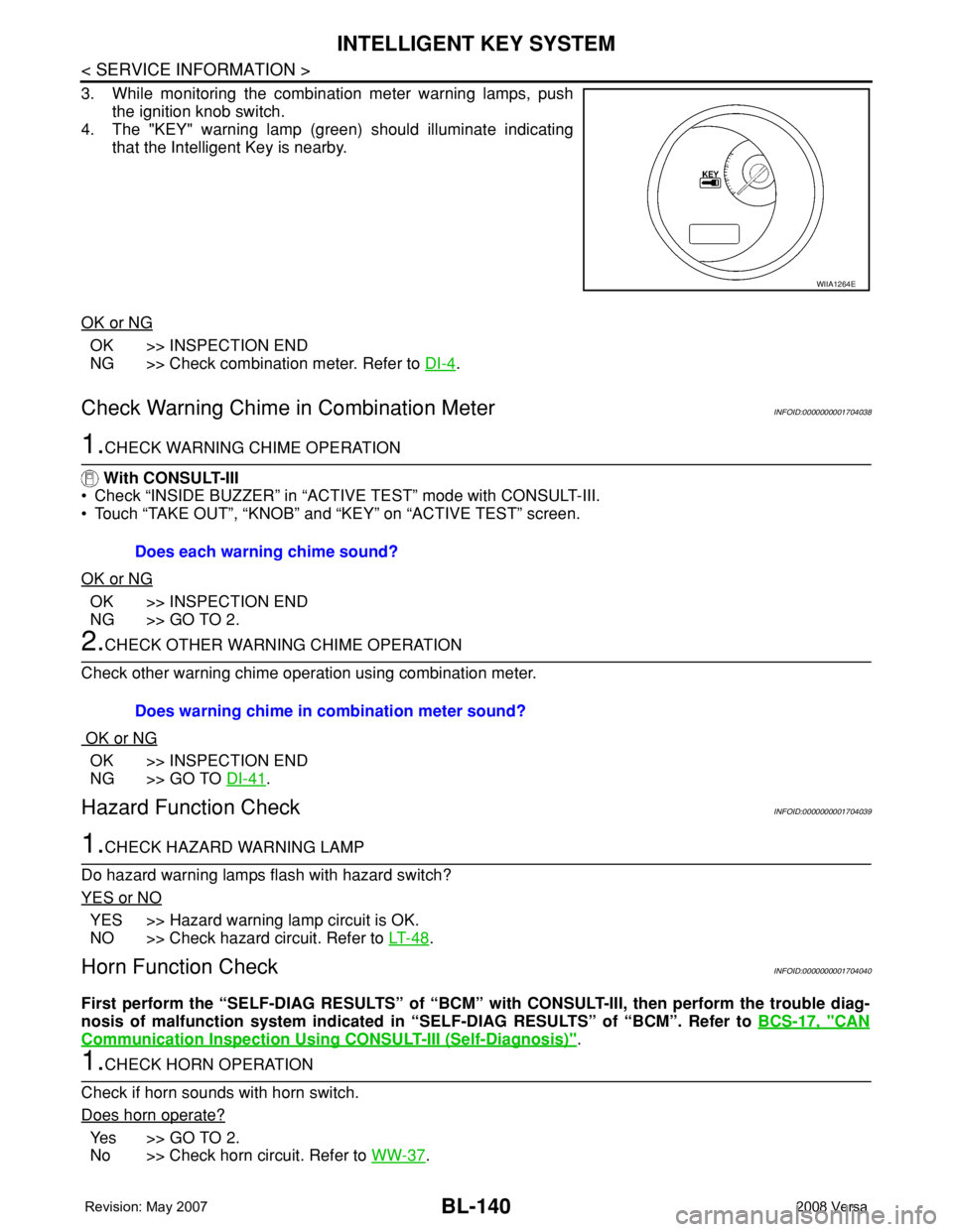
3. While monitoring the combination meter warning lamps, push
the ignition knob switch.
4. The "KEY" warning lamp (green) should illuminate indicating
that the Intelligent Key is nearby.
OK or NG
OK >> INSPECTION END
NG >> Check combination meter. Refer to DI-4
.
Check Warning Chime in Combination MeterINFOID:0000000001704038
1.CHECK WARNING CHIME OPERATION
With CONSULT-III
• Check “INSIDE BUZZER” in “ACTIVE TEST” mode with CONSULT-III.
• Touch “TAKE OUT”, “KNOB” and “KEY” on “ACTIVE TEST” screen.
OK or NG
OK >> INSPECTION END
NG >> GO TO 2.
2.CHECK OTHER WARNING CHIME OPERATION
Check other warning chime operation using combination meter.
OK or NG
OK >> INSPECTION END
NG >> GO TO DI-41
.
Hazard Function CheckINFOID:0000000001704039
1.CHECK HAZARD WARNING LAMP
Do hazard warning lamps flash with hazard switch?
YES or NO
YES >> Hazard warning lamp circuit is OK.
NO >> Check hazard circuit. Refer to LT- 4 8
.
Horn Function CheckINFOID:0000000001704040
First perform the “SELF-DIAG RESULTS” of “BCM” with CONSULT-III, then perform the trouble diag-
nosis of malfunction system indicated in “SELF-DIAG RESULTS” of “BCM”. Refer to BCS-17, "
CAN
Communication Inspection Using CONSULT-III (Self-Diagnosis)".
1.CHECK HORN OPERATION
Check if horn sounds with horn switch.
Does horn operate?
Ye s > > G O T O 2 .
No >> Check horn circuit. Refer to WW-37
.
WIIA1264E
Does each warning chime sound?
Does warning chime in combination meter sound?
Page 575 of 2771
INTELLIGENT KEY SYSTEM
BL-141
< SERVICE INFORMATION >
C
D
E
F
G
H
J
K
L
MA
B
BL
N
O
P
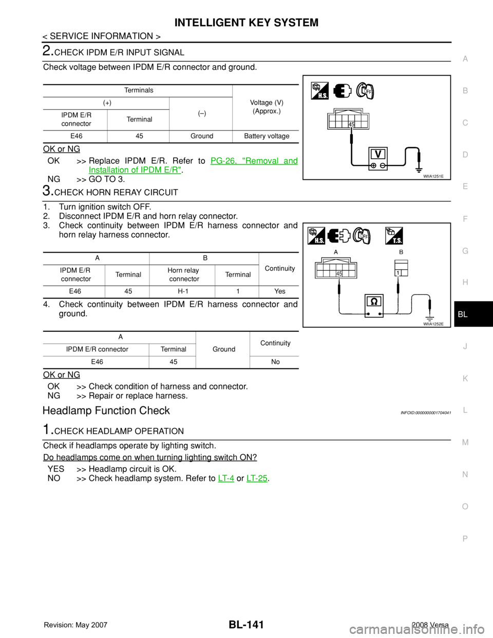
2.CHECK IPDM E/R INPUT SIGNAL
Check voltage between IPDM E/R connector and ground.
OK or NG
OK >> Replace IPDM E/R. Refer to PG-26, "Removal and
Installation of IPDM E/R".
NG >> GO TO 3.
3.CHECK HORN RERAY CIRCUIT
1. Turn ignition switch OFF.
2. Disconnect IPDM E/R and horn relay connector.
3. Check continuity between IPDM E/R harness connector and
horn relay harness connector.
4. Check continuity between IPDM E/R harness connector and
ground.
OK or NG
OK >> Check condition of harness and connector.
NG >> Repair or replace harness.
Headlamp Function CheckINFOID:0000000001704041
1.CHECK HEADLAMP OPERATION
Check if headlamps operate by lighting switch.
Do headlamps come on when turning lighting switch ON?
YES >> Headlamp circuit is OK.
NO >> Check headlamp system. Refer to LT- 4
or LT- 2 5.
Te r m i n a l s
Voltage (V)
(Approx.) (+)
(–)
IPDM E/R
connectorTe r m i n a l
E46 45 Ground Battery voltage
WIIA1251E
AB
Continuity
IPDM E/R
connectorTe r m i n a lHorn relay
connectorTe r m i n a l
E46 45 H-1 1 Yes
A
GroundContinuity
IPDM E/R connector Terminal
E46 45 No
WIIA1252E
Page 585 of 2771
FRONT DOOR LOCK
BL-151
< SERVICE INFORMATION >
C
D
E
F
G
H
J
K
L
MA
B
BL
N
O
P
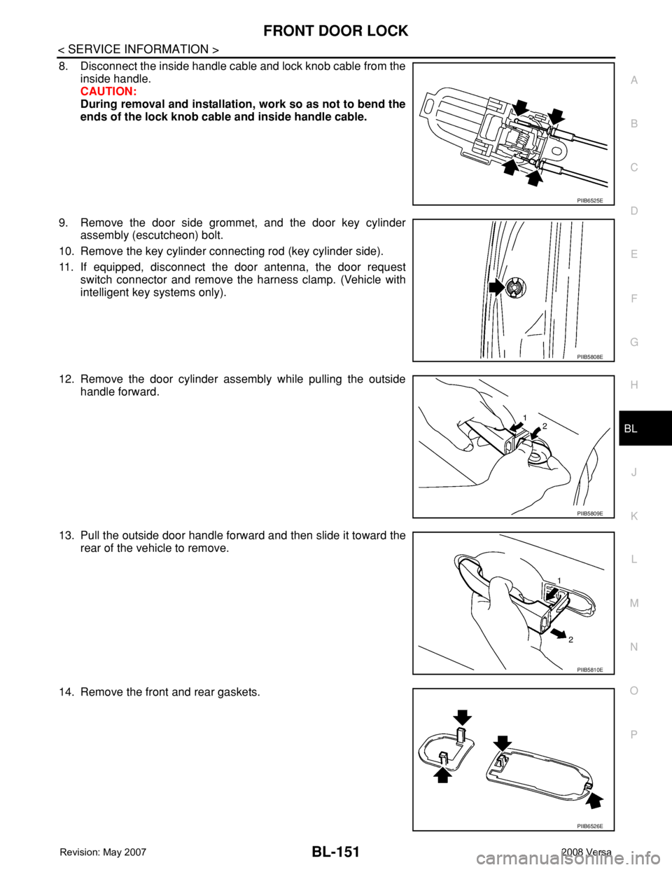
8. Disconnect the inside handle cable and lock knob cable from the
inside handle.
CAUTION:
During removal and installation, work so as not to bend the
ends of the lock knob cable and inside handle cable.
9. Remove the door side grommet, and the door key cylinder
assembly (escutcheon) bolt.
10. Remove the key cylinder connecting rod (key cylinder side).
11. If equipped, disconnect the door antenna, the door request
switch connector and remove the harness clamp. (Vehicle with
intelligent key systems only).
12. Remove the door cylinder assembly while pulling the outside
handle forward.
13. Pull the outside door handle forward and then slide it toward the
rear of the vehicle to remove.
14. Remove the front and rear gaskets.
PIIB6525E
PIIB5808E
PIIB5809E
PIIB5810E
PIIB6526E
Page 590 of 2771
BL-156
< SERVICE INFORMATION >
BACK DOOR LOCK
BACK DOOR LOCK
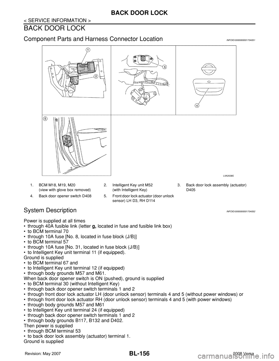
Component Parts and Harness Connector LocationINFOID:0000000001704051
System DescriptionINFOID:0000000001704052
Power is supplied at all times
• through 40A fusible link (letter g, located in fuse and fusible link box)
• to BCM terminal 70
• through 10A fuse [No. 8, located in fuse block (J/B)]
• to BCM terminal 57
• through 10A fuse [No. 31, located in fuse block (J/B)]
• to Intelligent Key unit terminal 11 (if equipped).
Ground is supplied
• to BCM terminal 67 and
• to Intelligent Key unit terminal 12 (if equipped)
• through body grounds M57 and M61.
When back door opener switch is ON (pushed), ground is supplied
• to BCM terminal 30 (without Intelligent Key)
• through back door opener switch terminals 1 and 2
• through front door lock actuator LH (door unlock sensor) terminals 4 and 5 (without power windows) or
• through front door lock actuator RH (door unlock sensor) terminals 4 and 5 (with power windows)
• through body grounds M57 and M61
• to Intelligent Key unit terminal 24 (if equipped)
• through back door opener switch terminals 1 and 2
• through body grounds B117, B132 and D402.
Then power is supplied
• through BCM terminal 53
• to back door lock assembly (actuator) terminal 1.
Ground is supplied
LIIA2638E
1. BCM M18, M19, M20
(view with glove box removed)2. Intelligent Key unit M52
(with Intelligent Key)3. Back door lock assembly (actuator)
D405
4. Back door opener switch D408 5. Front door lock actuator (door unlock
sensor) LH D3, RH D114
Page 593 of 2771

BACK DOOR LOCK
BL-159
< SERVICE INFORMATION >
C
D
E
F
G
H
J
K
L
MA
B
BL
N
O
P
CONSULT-III Function (BCM)INFOID:0000000001704056
CONSULT-III can display each diagnostic item using the diagnostic test modes shown following.
CONSULT-III APPLICATION ITEMS
Data Monitor
* : With Intelligent Key system
** : Without Intelligent Key system
Active Test
Work FlowINFOID:0000000001704057
1. Check the symptom and customer's requests.
2. Understand the outline of system. Refer to BL-156, "
System Description".
3. Repair or replace any malfunctioning parts. Refer to BL-159, "
Trouble Diagnosis Chart by Symptom".
4. Does back door opener operate normally? If Yes, GO TO 5. If No, GO TO 3.
5. INSPECTION END
Trouble Diagnosis Chart by SymptomINFOID:0000000001704058
BCM
diagnostic test itemDiagnostic mode Description
Inspection by partWORK SUPPORTSupports inspections and adjustments. Commands are transmitted to the
BCM for setting the status suitable for required operation, input/output sig-
nals are received from the BCM and received date is displayed.
DATA MONITOR Displays BCM input/output data in real time.
ACTIVE TESTOperation of electrical loads can be checked by sending drive signal to
them.
SELF-DIAG RESULTS Displays BCM self-diagnosis results.
CAN DIAG SUPPORT MNTRThe result of transmit/receive diagnosis of CAN communication can be
read.
ECU PART NUMBER BCM part number can be read.
CONFIGURATION Performs BCM configuration read/write functions.
Monitor item Content
IGN ON SW Indicates [ON/OFF] condition of ignition switch.
KEYLESS TRUNK** This is displayed even when it is not equipped.
I-KEY TRUNK* Momentarily indicates [ON/OFF] condition of back door open signal from back door opener switch.
TRNK OPNR SW** Indicates [ON/OFF] condition of back door open signal from back door opener switch.
VEHICLE SPEED This is displayed even when it is not equipped.
Test item Content
TRUNK/BACK DOORThis test is able to check back door lock assembly (actuator) unlock operation.
Actuator opens back door lock assembly when “OPEN” on CONSULT-III screen is touched.
Symptom Diagnoses/service procedureReference
page
Back door opener does not operate.
(Without Intelligent Key or power windows)1. Check BCM power supply and ground circuit.BCS-15
2. Check back door opener switch circuit.BL-160
3. Check back door lock assembly (actuator) circuit.BL-166
4. Replace BCM.BCS-18
Page 594 of 2771
BL-160
< SERVICE INFORMATION >
BACK DOOR LOCK
BCM Power Supply and Ground Circuit
INFOID:0000000001704059
Refer to BCS-15, "BCM Power Supply and Ground Circuit Inspection".
Check Back Door Opener Switch Circuit (Without Intelligent Key or Power Windows)
INFOID:0000000001704060
1.CHECK BACK DOOR OPENER SWITCH SIGNAL 1
With CONSULT-III
1. Insure front door lock knob LH is turned to the UNLOCK position.
2. Check back door opener switch (“TRNK OPNR SW”) in “DATA MONITOR” mode with CONSULT-III.
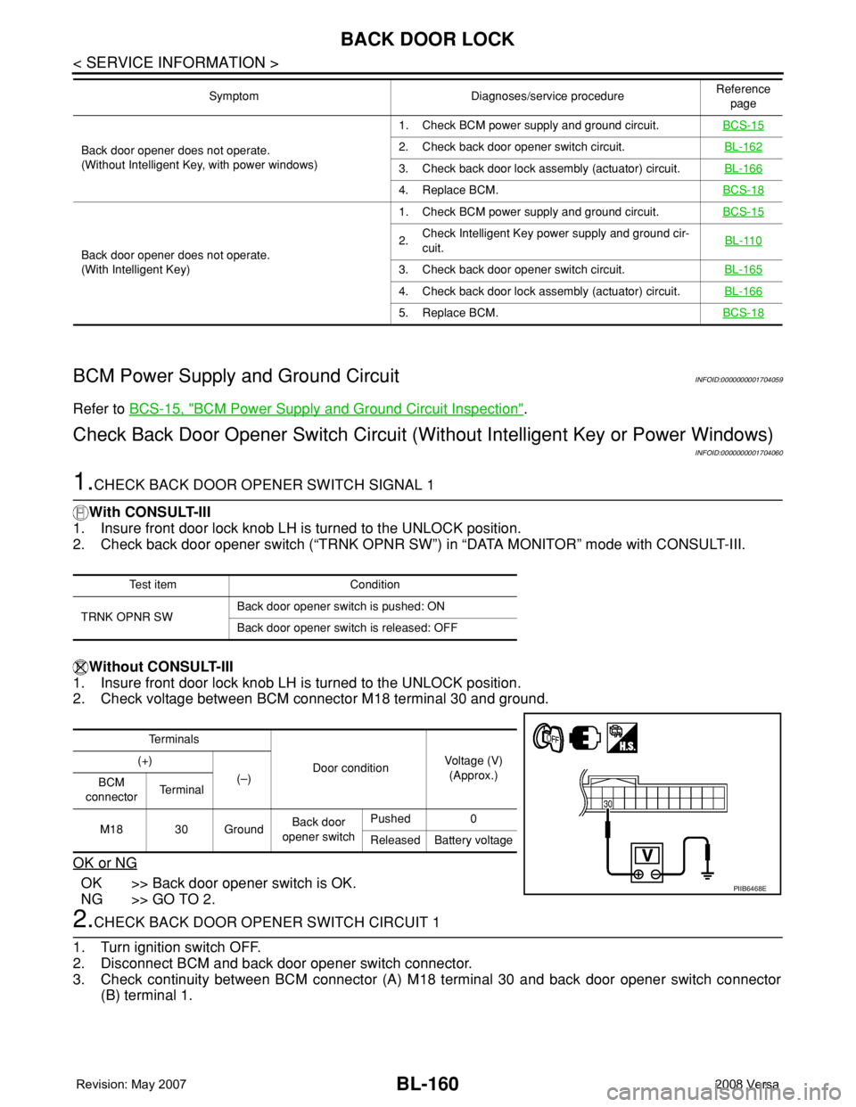
Without CONSULT-III
1. Insure front door lock knob LH is turned to the UNLOCK position.
2. Check voltage between BCM connector M18 terminal 30 and ground.
OK or NG
OK >> Back door opener switch is OK.
NG >> GO TO 2.
2.CHECK BACK DOOR OPENER SWITCH CIRCUIT 1
1. Turn ignition switch OFF.
2. Disconnect BCM and back door opener switch connector.
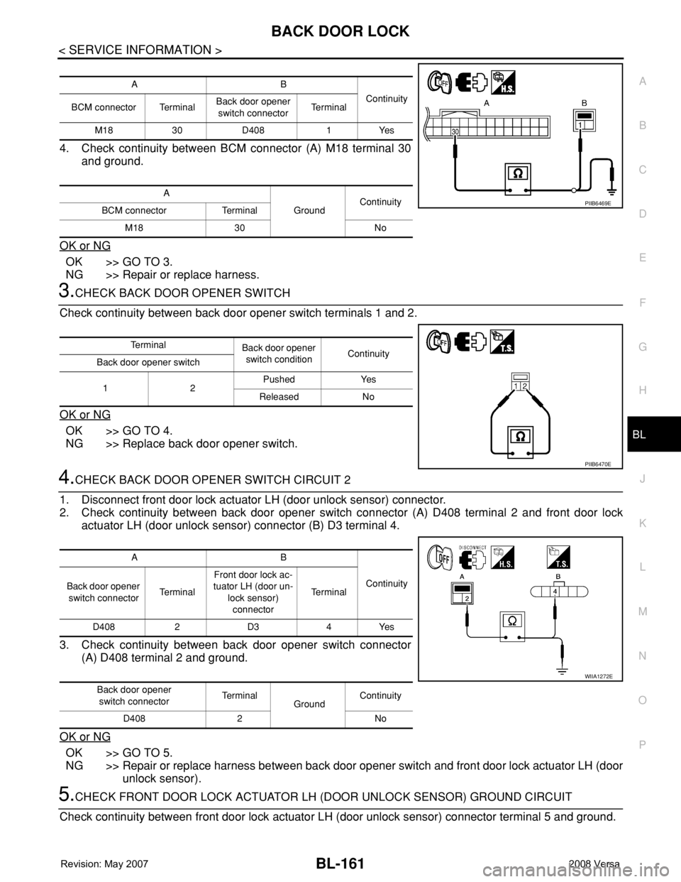
3. Check continuity between BCM connector (A) M18 terminal 30 and back door opener switch connector
(B) terminal 1.
Back door opener does not operate.
(Without Intelligent Key, with power windows)1. Check BCM power supply and ground circuit.BCS-152. Check back door opener switch circuit.BL-162
3. Check back door lock assembly (actuator) circuit.BL-166
4. Replace BCM.BCS-18
Back door opener does not operate.
(With Intelligent Key)1. Check BCM power supply and ground circuit.BCS-15
2.Check Intelligent Key power supply and ground cir-
cuit.BL-110
3. Check back door opener switch circuit.BL-165
4. Check back door lock assembly (actuator) circuit.BL-166
5. Replace BCM.BCS-18
Symptom Diagnoses/service procedureReference
page
Test item Condition
TRNK OPNR SWBack door opener switch is pushed: ON
Back door opener switch is released: OFF
Te r m i n a l s
Door conditionVoltage (V)
(Approx.) (+)
(–)
BCM
connectorTe r m i n a l
M18 30 GroundBack door
opener switchPushed 0
Released Battery voltage
PIIB6468E
Page 595 of 2771
BACK DOOR LOCK
BL-161
< SERVICE INFORMATION >
C
D
E
F
G
H
J
K
L
MA
B
BL
N
O
P
4. Check continuity between BCM connector (A) M18 terminal 30
and ground.
OK or NG
OK >> GO TO 3.
NG >> Repair or replace harness.
3.CHECK BACK DOOR OPENER SWITCH
Check continuity between back door opener switch terminals 1 and 2.
OK or NG
OK >> GO TO 4.
NG >> Replace back door opener switch.
4.CHECK BACK DOOR OPENER SWITCH CIRCUIT 2
1. Disconnect front door lock actuator LH (door unlock sensor) connector.
2. Check continuity between back door opener switch connector (A) D408 terminal 2 and front door lock
actuator LH (door unlock sensor) connector (B) D3 terminal 4.
3. Check continuity between back door opener switch connector
(A) D408 terminal 2 and ground.
OK or NG
OK >> GO TO 5.
NG >> Repair or replace harness between back door opener switch and front door lock actuator LH (door
unlock sensor).
5.CHECK FRONT DOOR LOCK ACTUATOR LH (DOOR UNLOCK SENSOR) GROUND CIRCUIT
Check continuity between front door lock actuator LH (door unlock sensor) connector terminal 5 and ground.
AB
Continuity
BCM connector TerminalBack door opener
switch connectorTe r m i n a l
M18 30 D408 1 Yes
A
GroundContinuity
BCM connector Terminal
M18 30 No
PIIB6469E
Te r m i n a l
Back door opener
switch conditionContinuity
Back door opener switch
12Pushed Yes
Released No
PIIB6470E
AB
Continuity
Back door opener
switch connectorTe r m i n a lFront door lock ac-
tuator LH (door un-
lock sensor)
connectorTe r m i n a l
D408 2 D3 4 Yes
Back door opener
switch connectorTe r m i n a l
GroundContinuity
D408 2 No
WIIA1272E
Page 596 of 2771
BL-162
< SERVICE INFORMATION >
BACK DOOR LOCK
OK or NG
OK >> GO TO 6.
NG >> Repair or replace harness.
6.CHECK UNLOCK SENSOR FUNCTION
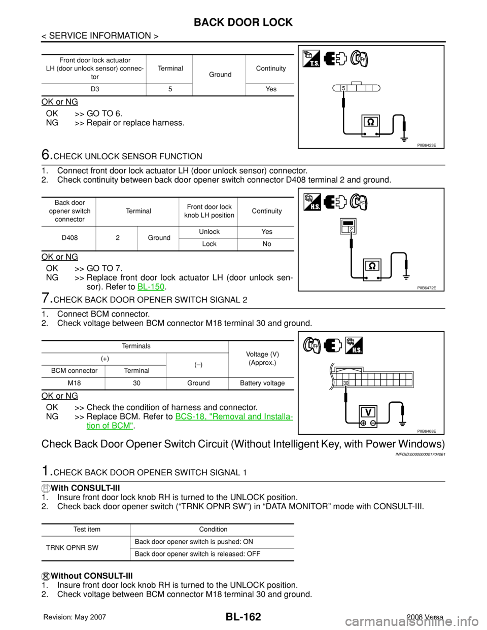
1. Connect front door lock actuator LH (door unlock sensor) connector.
2. Check continuity between back door opener switch connector D408 terminal 2 and ground.
OK or NG
OK >> GO TO 7.
NG >> Replace front door lock actuator LH (door unlock sen-
sor). Refer to BL-150
.
7.CHECK BACK DOOR OPENER SWITCH SIGNAL 2
1. Connect BCM connector.
2. Check voltage between BCM connector M18 terminal 30 and ground.
OK or NG
OK >> Check the condition of harness and connector.
NG >> Replace BCM. Refer to BCS-18, "
Removal and Installa-
tion of BCM".
Check Back Door Opener Switch Circuit (Without Intelligent Key, with Power Windows)
INFOID:0000000001704061
1.CHECK BACK DOOR OPENER SWITCH SIGNAL 1
With CONSULT-III
1. Insure front door lock knob RH is turned to the UNLOCK position.
2. Check back door opener switch (“TRNK OPNR SW”) in “DATA MONITOR” mode with CONSULT-III.
Without CONSULT-III
1. Insure front door lock knob RH is turned to the UNLOCK position.
2. Check voltage between BCM connector M18 terminal 30 and ground.
Front door lock actuator
LH (door unlock sensor) connec-
torTe r m i n a l
GroundContinuity
D3 5 Yes
PIIB6423E
Back door
opener switch
connectorTe r m i n a lFront door lock
knob LH positionContinuity
D408 2 GroundUnlock Yes
Lock No
PIIB6472E
Te r m i n a l s
Voltage (V)
(Approx.) (+)
(–)
BCM connector Terminal
M18 30 Ground Battery voltage
PIIB6468E
Test item Condition
TRNK OPNR SWBack door opener switch is pushed: ON
Back door opener switch is released: OFF