Page 597 of 2771
BACK DOOR LOCK
BL-163
< SERVICE INFORMATION >
C
D
E
F
G
H
J
K
L
MA
B
BL
N
O
P
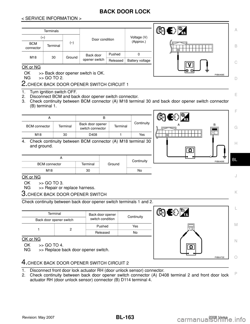
OK or NG
OK >> Back door opener switch is OK.
NG >> GO TO 2.
2.CHECK BACK DOOR OPENER SWITCH CIRCUIT 1
1. Turn ignition switch OFF.
2. Disconnect BCM and back door opener switch connector.
3. Check continuity between BCM connector (A) M18 terminal 30 and back door opener switch connector
(B) terminal 1.
4. Check continuity between BCM connector (A) M18 terminal 30
and ground.
OK or NG
OK >> GO TO 3.
NG >> Repair or replace harness.
3.CHECK BACK DOOR OPENER SWITCH
Check continuity between back door opener switch terminals 1 and 2.
OK or NG
OK >> GO TO 4.
NG >> Replace back door opener switch.
4.CHECK BACK DOOR OPENER SWITCH CIRCUIT 2
1. Disconnect front door lock actuator RH (door unlock sensor) connector.
2. Check continuity between back door opener switch connector (A) D408 terminal 2 and front door lock
actuator RH (door unlock sensor) connector (B) D114 terminal 4.
Te r m i n a l s
Door conditionVoltage (V)
(Approx.) (+)
(–)
BCM
connectorTe r m i n a l
M18 30 GroundBack door
opener switchPushed 0
Released Battery voltage
PIIB6468E
AB
Continuity
BCM connector TerminalBack door opener
switch connectorTe r m i n a l
M18 30 D408 1 Yes
A
GroundContinuity
BCM connector Terminal
M18 30 No
PIIB6469E
Te r m i n a l
Back door opener
switch conditionContinuity
Back door opener switch
12Pushed Yes
Released No
PIIB6470E
Page 598 of 2771
BL-164
< SERVICE INFORMATION >
BACK DOOR LOCK
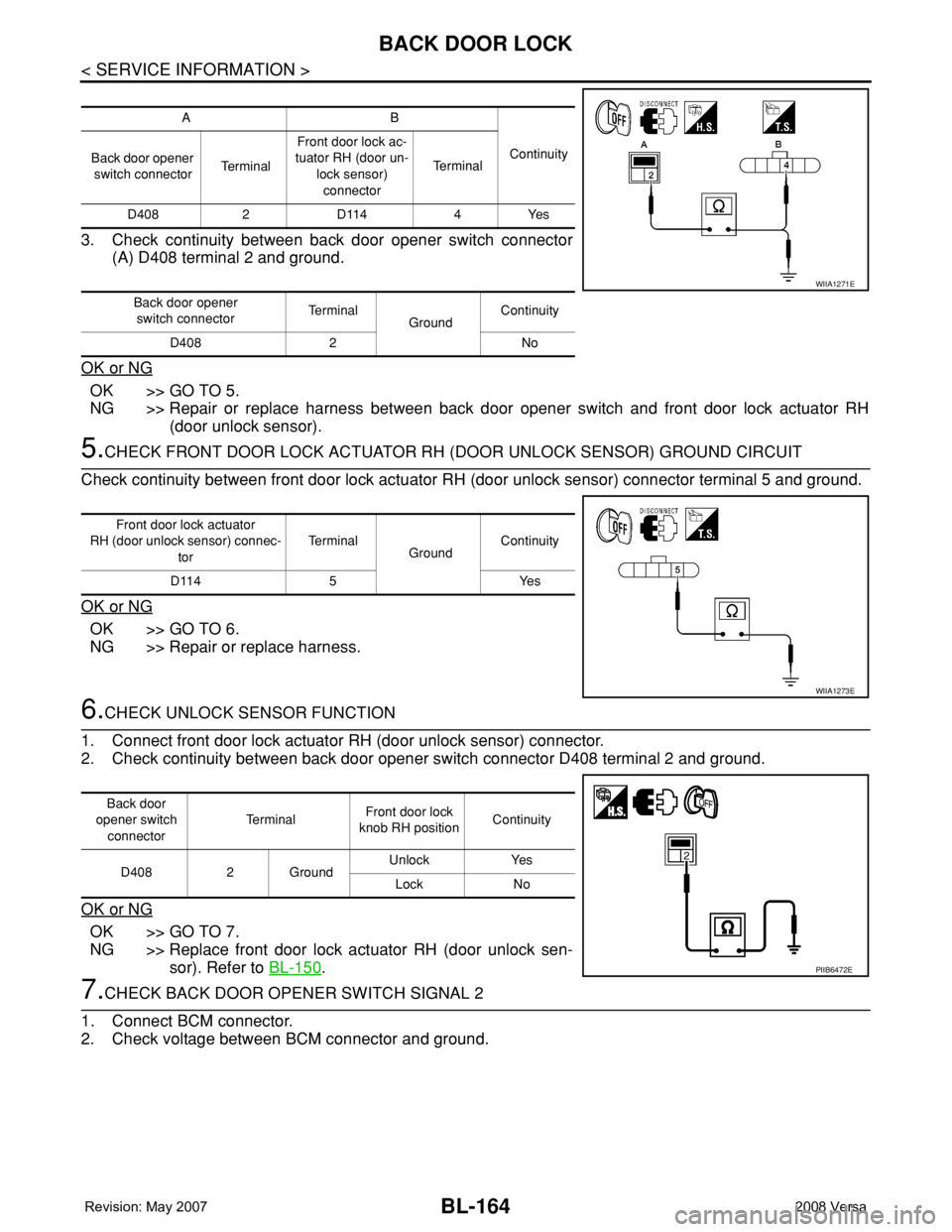
3. Check continuity between back door opener switch connector
(A) D408 terminal 2 and ground.
OK or NG
OK >> GO TO 5.
NG >> Repair or replace harness between back door opener switch and front door lock actuator RH
(door unlock sensor).
5.CHECK FRONT DOOR LOCK ACTUATOR RH (DOOR UNLOCK SENSOR) GROUND CIRCUIT
Check continuity between front door lock actuator RH (door unlock sensor) connector terminal 5 and ground.
OK or NG
OK >> GO TO 6.
NG >> Repair or replace harness.
6.CHECK UNLOCK SENSOR FUNCTION
1. Connect front door lock actuator RH (door unlock sensor) connector.
2. Check continuity between back door opener switch connector D408 terminal 2 and ground.
OK or NG
OK >> GO TO 7.
NG >> Replace front door lock actuator RH (door unlock sen-
sor). Refer to BL-150
.
7.CHECK BACK DOOR OPENER SWITCH SIGNAL 2
1. Connect BCM connector.
2. Check voltage between BCM connector and ground.
AB
Continuity
Back door opener
switch connectorTe r m i n a lFront door lock ac-
tuator RH (door un-
lock sensor)
connectorTe r m i n a l
D408 2 D114 4 Yes
Back door opener
switch connectorTe r m i n a l
GroundContinuity
D408 2 No
WIIA1271E
Front door lock actuator
RH (door unlock sensor) connec-
torTe r m i n a l
GroundContinuity
D114 5 Yes
WIIA1273E
Back door
opener switch
connectorTe r m i n a lFront door lock
knob RH positionContinuity
D408 2 GroundUnlock Yes
Lock No
PIIB6472E
Page 599 of 2771
BACK DOOR LOCK
BL-165
< SERVICE INFORMATION >
C
D
E
F
G
H
J
K
L
MA
B
BL
N
O
P
OK or NG
OK >> Check the condition of harness and connector.
NG >> Replace BCM. Refer to BCS-18, "
Removal and Installa-
tion of BCM".
Check Back Door Opener Switch Circuit (With Intelligent Key)INFOID:0000000001704062
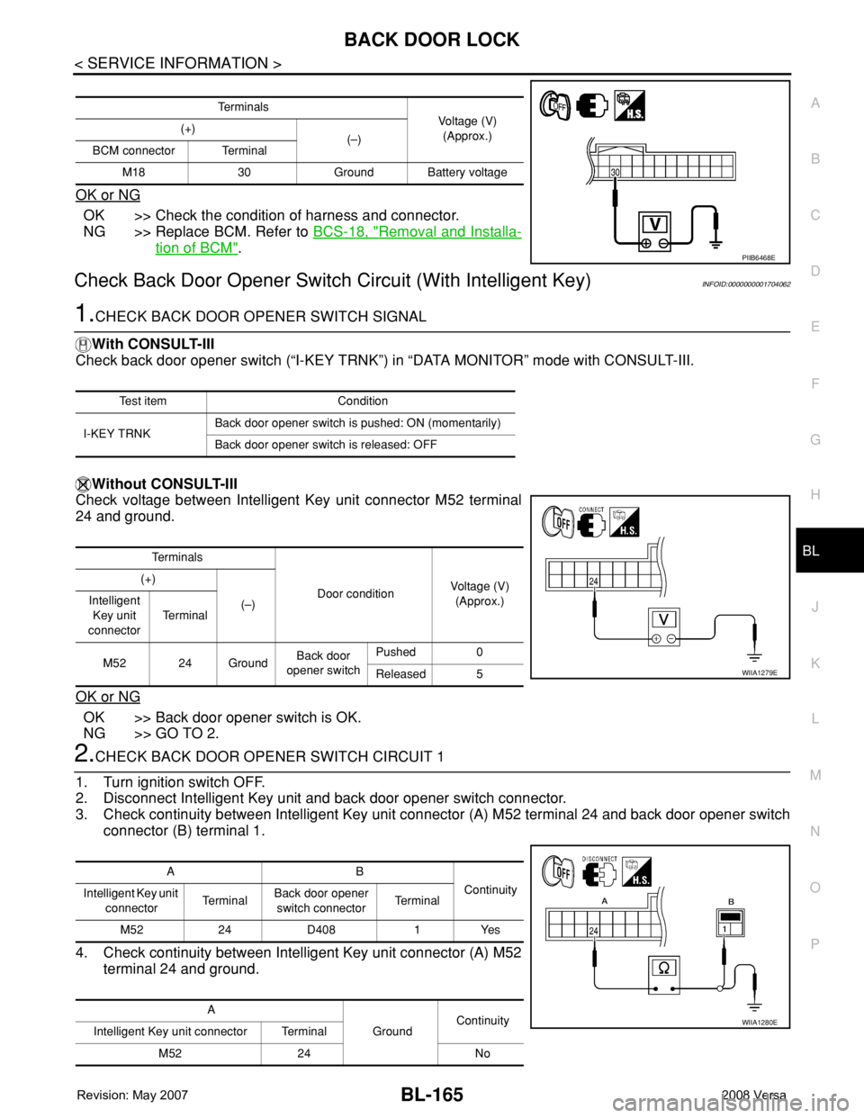
1.CHECK BACK DOOR OPENER SWITCH SIGNAL
With CONSULT-III
Check back door opener switch (“I-KEY TRNK”) in “DATA MONITOR” mode with CONSULT-III.
Without CONSULT-III
Check voltage between Intelligent Key unit connector M52 terminal
24 and ground.
OK or NG
OK >> Back door opener switch is OK.
NG >> GO TO 2.
2.CHECK BACK DOOR OPENER SWITCH CIRCUIT 1
1. Turn ignition switch OFF.
2. Disconnect Intelligent Key unit and back door opener switch connector.
3. Check continuity between Intelligent Key unit connector (A) M52 terminal 24 and back door opener switch
connector (B) terminal 1.
4. Check continuity between Intelligent Key unit connector (A) M52
terminal 24 and ground.
Te r m i n a l s
Voltage (V)
(Approx.) (+)
(–)
BCM connector Terminal
M18 30 Ground Battery voltage
PIIB6468E
Test item Condition
I-KEY TRNKBack door opener switch is pushed: ON (momentarily)
Back door opener switch is released: OFF
Te r m i n a l s
Door conditionVoltage (V)
(Approx.) (+)
(–) Intelligent
Key unit
connectorTe r m i n a l
M52 24 GroundBack door
opener switchPushed 0
Released 5
WIIA1279E
AB
Continuity
Intelligent Key unit
connectorTe r m i n a lBack door opener
switch connectorTe r m i n a l
M52 24 D408 1 Yes
A
GroundContinuity
Intelligent Key unit connector Terminal
M52 24 No
WIIA1280E
Page 600 of 2771
BL-166
< SERVICE INFORMATION >
BACK DOOR LOCK
OK or NG
OK >> GO TO 3.
NG >> Repair or replace harness.
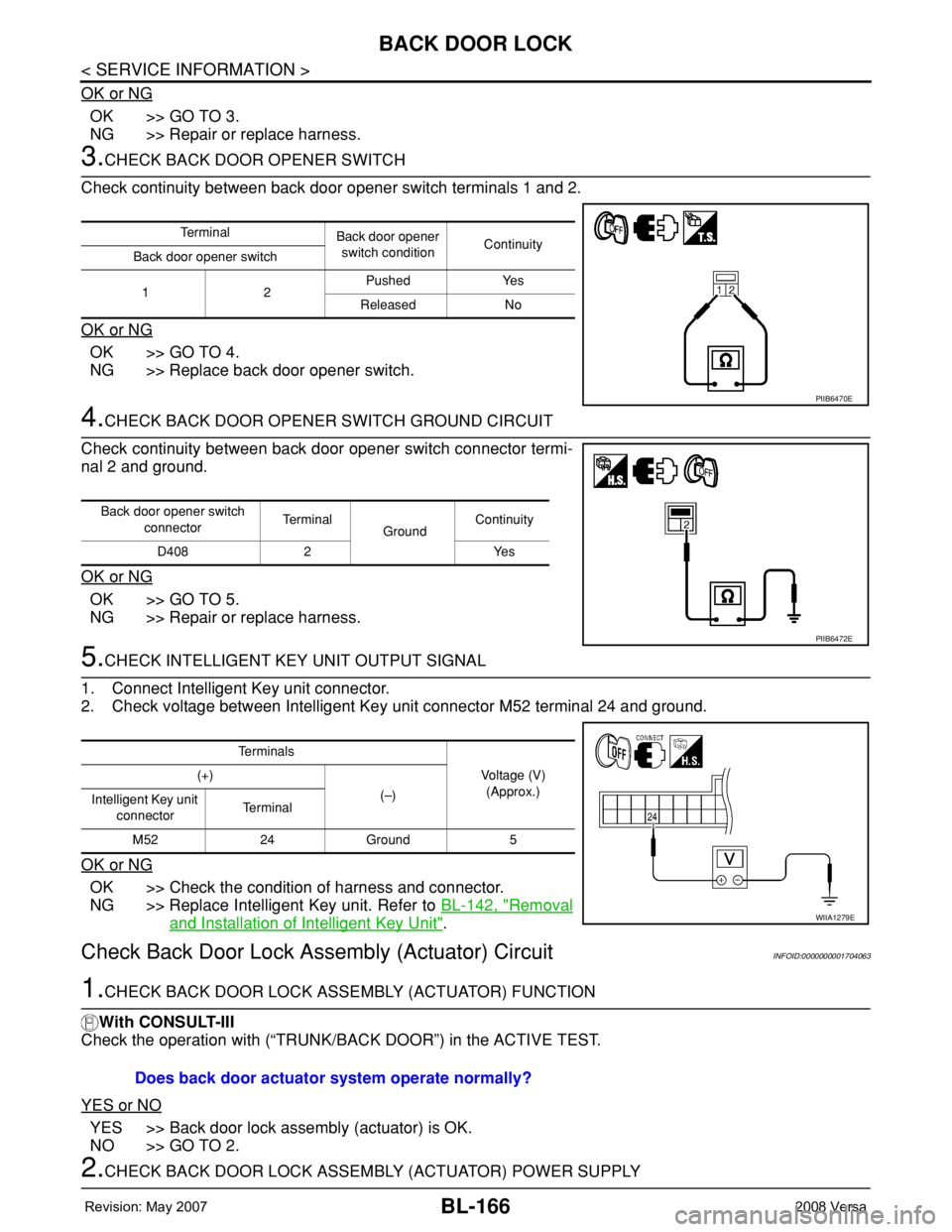
3.CHECK BACK DOOR OPENER SWITCH
Check continuity between back door opener switch terminals 1 and 2.
OK or NG
OK >> GO TO 4.
NG >> Replace back door opener switch.
4.CHECK BACK DOOR OPENER SWITCH GROUND CIRCUIT
Check continuity between back door opener switch connector termi-
nal 2 and ground.
OK or NG
OK >> GO TO 5.
NG >> Repair or replace harness.
5.CHECK INTELLIGENT KEY UNIT OUTPUT SIGNAL
1. Connect Intelligent Key unit connector.
2. Check voltage between Intelligent Key unit connector M52 terminal 24 and ground.
OK or NG
OK >> Check the condition of harness and connector.
NG >> Replace Intelligent Key unit. Refer to BL-142, "
Removal
and Installation of Intelligent Key Unit".
Check Back Door Lock Assembly (Actuator) CircuitINFOID:0000000001704063
1.CHECK BACK DOOR LOCK ASSEMBLY (ACTUATOR) FUNCTION
With CONSULT-III
Check the operation with (“TRUNK/BACK DOOR”) in the ACTIVE TEST.
YES or NO
YES >> Back door lock assembly (actuator) is OK.
NO >> GO TO 2.
2.CHECK BACK DOOR LOCK ASSEMBLY (ACTUATOR) POWER SUPPLY
Te r m i n a l
Back door opener
switch conditionContinuity
Back door opener switch
12Pushed Yes
Released No
PIIB6470E
Back door opener switch
connectorTe r m i n a l
GroundContinuity
D408 2 Yes
PIIB6472E
Te r m i n a l s
Voltage (V)
(Approx.) (+)
(–)
Intelligent Key unit
connectorTe r m i n a l
M52 24 Ground 5
WIIA1279E
Does back door actuator system operate normally?
Page 601 of 2771
BACK DOOR LOCK
BL-167
< SERVICE INFORMATION >
C
D
E
F
G
H
J
K
L
MA
B
BL
N
O
P
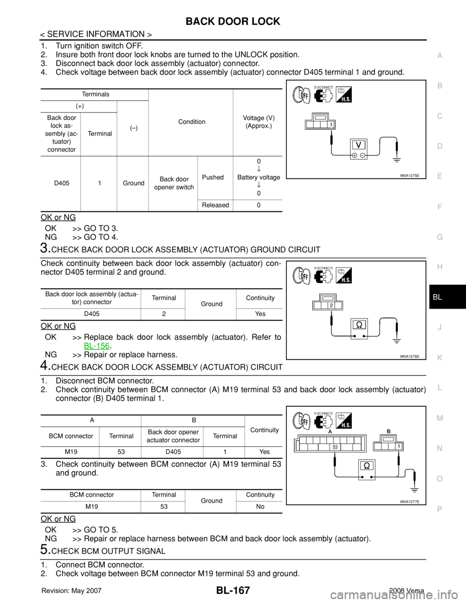
1. Turn ignition switch OFF.
2. Insure both front door lock knobs are turned to the UNLOCK position.
3. Disconnect back door lock assembly (actuator) connector.
4. Check voltage between back door lock assembly (actuator) connector D405 terminal 1 and ground.
OK or NG
OK >> GO TO 3.
NG >> GO TO 4.
3.CHECK BACK DOOR LOCK ASSEMBLY (ACTUATOR) GROUND CIRCUIT
Check continuity between back door lock assembly (actuator) con-
nector D405 terminal 2 and ground.
OK or NG
OK >> Replace back door lock assembly (actuator). Refer to
BL-156
.
NG >> Repair or replace harness.
4.CHECK BACK DOOR LOCK ASSEMBLY (ACTUATOR) CIRCUIT
1. Disconnect BCM connector.
2. Check continuity between BCM connector (A) M19 terminal 53 and back door lock assembly (actuator)
connector (B) D405 terminal 1.
3. Check continuity between BCM connector (A) M19 terminal 53
and ground.
OK or NG
OK >> GO TO 5.
NG >> Repair or replace harness between BCM and back door lock assembly (actuator).
5.CHECK BCM OUTPUT SIGNAL
1. Connect BCM connector.
2. Check voltage between BCM connector M19 terminal 53 and ground.
Te r m i n a l s
ConditionVoltage (V)
(Approx.) (+)
(–) Back door
lock as-
sembly (ac-
tuator)
connectorTe r m i n a l
D405 1 GroundBack door
opener switchPushed0
↓
Battery voltage
↓
0
Released 0
WIIA1275E
Back door lock assembly (actua-
tor) connectorTe r m i n a l
GroundContinuity
D405 2 Yes
WIIA1276E
AB
Continuity
BCM connector TerminalBack door opener
actuator connectorTe r m i n a l
M19 53 D405 1 Yes
BCM connector Terminal
GroundContinuity
M19 53 No
WIIA1277E
Page 602 of 2771
BL-168
< SERVICE INFORMATION >
BACK DOOR LOCK
OK or NG
OK >> Check the condition of harness and connector.
NG >> Replace BCM. Refer to BCS-18, "
Removal and Installation of BCM".
Removal and InstallationINFOID:0000000001704064
BACK DOOR LOCK
Removal
1. Remove the back door finisher lower. Refer to EI-36.
2. Remove the bolts, disconnect the electrical connector and sepa-
rate the lock from the door.
Installation
Installation is in the reverse order of removal.
BACK DOOR HANDLE
Removal
1. Remove the back door finisher lower. Refer to EI-36.
2. Disconnect the harness connectors (1), remove the nuts and the
back door handle (A).
Te r m i n a l s
ConditionVoltage (V)
(Approx.) (+)
(–)
BCM
connectorTe r m i n a l
M19 53 GroundBack door
opener switchPushed0
↓
Battery voltage
↓
0
Released 0
PIIB6477E
LIIA2607E
LIIA2669E
Page 603 of 2771
BACK DOOR LOCK
BL-169
< SERVICE INFORMATION >
C
D
E
F
G
H
J
K
L
MA
B
BL
N
O
P
3. Release the clips and remove the switch from the housing.
Installation
Installation is in the reverse order of removal.
LIIA2609E
Page 607 of 2771
TRUNK LID OPENER
BL-173
< SERVICE INFORMATION >
C
D
E
F
G
H
J
K
L
MA
B
BL
N
O
P
TRUNK LID OPENER
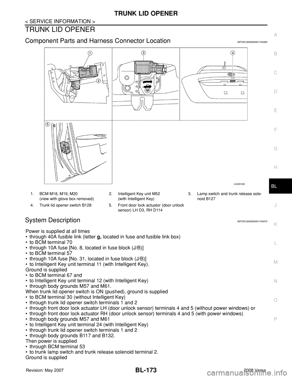
Component Parts and Harness Connector LocationINFOID:0000000001704069
System DescriptionINFOID:0000000001704070
Power is supplied at all times
• through 40A fusible link (letter g, located in fuse and fusible link box)
• to BCM terminal 70
• through 10A fuse [No. 8, located in fuse block (J/B)]
• to BCM terminal 57
• through 10A fuse [No. 31, located in fuse block (J/B)]
• to Intelligent Key unit terminal 11 (with Intelligent Key).
Ground is supplied
• to BCM terminal 67 and
• to Intelligent Key unit terminal 12 (with Intelligent Key)
• through body grounds M57 and M61.
When trunk lid opener switch is ON (pushed), ground is supplied
• to BCM terminal 30 (without Intelligent Key)
• through trunk lid opener switch terminals 1 and 2
• through front door lock actuator LH (door unlock sensor) terminals 4 and 5 (without power windows) or
• through front door lock actuator RH (door unlock sensor) terminals 4 and 5 (with power windows)
• through body grounds M57 and M61
• to Intelligent Key unit terminal 24 (with Intelligent Key)
• through trunk lid opener switch terminals 1 and 2
• through body grounds B117 and B132.
Then power is supplied
• through BCM terminal 53
• to trunk lamp switch and trunk release solenoid terminal 2.
Ground is supplied
LIIA2918E
1. BCM M18, M19, M20
(view with glove box removed)2. Intelligent Key unit M52
(with Intelligent Key)3. Lamp switch and trunk release sole-
noid B127
4. Trunk lid opener switch B128 5. Front door lock actuator (door unlock
sensor) LH D3, RH D114