2008 NISSAN TIIDA fuel pressure
[x] Cancel search: fuel pressurePage 1153 of 2771
BASIC SERVICE PROCEDURE
EC-79
< SERVICE INFORMATION >
C
D
E
F
G
H
I
J
K
L
MA
EC
N
P O
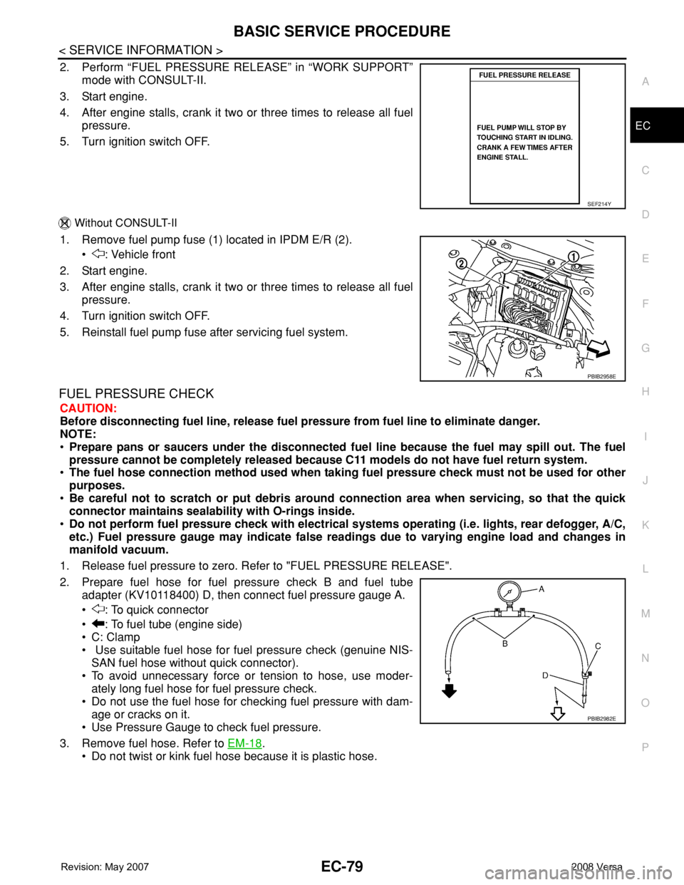
2. Perform “FUEL PRESSURE RELEASE” in “WORK SUPPORT”
mode with CONSULT-II.
3. Start engine.
4. After engine stalls, crank it two or three times to release all fuel
pressure.
5. Turn ignition switch OFF.
Without CONSULT-II
1. Remove fuel pump fuse (1) located in IPDM E/R (2).
• : Vehicle front
2. Start engine.
3. After engine stalls, crank it two or three times to release all fuel
pressure.
4. Turn ignition switch OFF.
5. Reinstall fuel pump fuse after servicing fuel system.
FUEL PRESSURE CHECK
CAUTION:
Before disconnecting fuel line, release fuel pressure from fuel line to eliminate danger.
NOTE:
•Prepare pans or saucers under the disconnected fuel line because the fuel may spill out. The fuel
pressure cannot be completely released because C11 models do not have fuel return system.
•The fuel hose connection method used when taking fuel pressure check must not be used for other
purposes.
•Be careful not to scratch or put debris around connection area when servicing, so that the quick
connector maintains sealability with O-rings inside.
•Do not perform fuel pressure check with electrical systems operating (i.e. lights, rear defogger, A/C,
etc.) Fuel pressure gauge may indicate false readings due to varying engine load and changes in
manifold vacuum.
1. Release fuel pressure to zero. Refer to "FUEL PRESSURE RELEASE".
2. Prepare fuel hose for fuel pressure check B and fuel tube
adapter (KV10118400) D, then connect fuel pressure gauge A.
• : To quick connector
• : To fuel tube (engine side)
• C: Clamp
• Use suitable fuel hose for fuel pressure check (genuine NIS-
SAN fuel hose without quick connector).
• To avoid unnecessary force or tension to hose, use moder-
ately long fuel hose for fuel pressure check.
• Do not use the fuel hose for checking fuel pressure with dam-
age or cracks on it.
• Use Pressure Gauge to check fuel pressure.
3. Remove fuel hose. Refer to EM-18
.
• Do not twist or kink fuel hose because it is plastic hose.
SEF214Y
PBIB2958E
PBIB2982E
Page 1154 of 2771
EC-80
< SERVICE INFORMATION >
BASIC SERVICE PROCEDURE
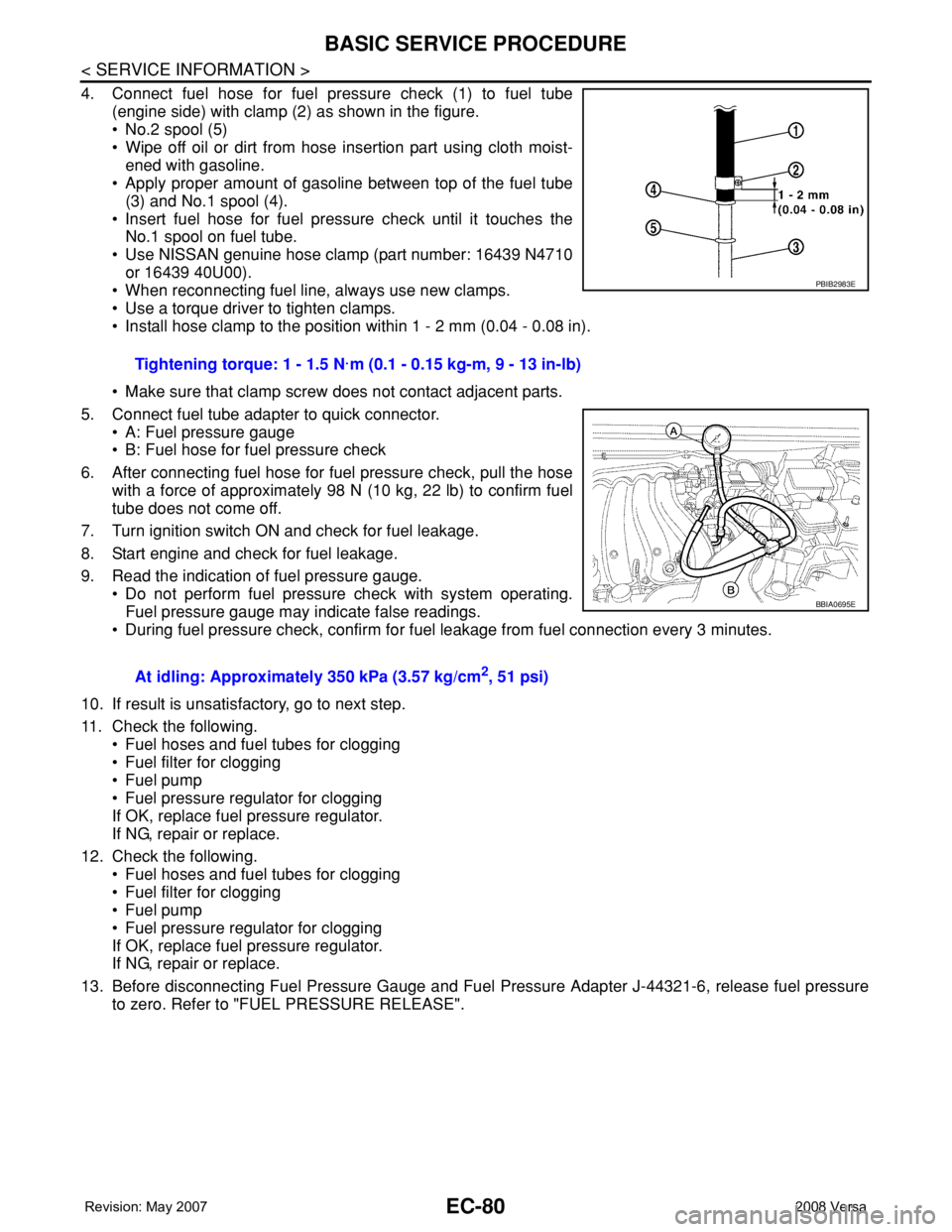
4. Connect fuel hose for fuel pressure check (1) to fuel tube
(engine side) with clamp (2) as shown in the figure.
• No.2 spool (5)
• Wipe off oil or dirt from hose insertion part using cloth moist-
ened with gasoline.
• Apply proper amount of gasoline between top of the fuel tube
(3) and No.1 spool (4).
• Insert fuel hose for fuel pressure check until it touches the
No.1 spool on fuel tube.
• Use NISSAN genuine hose clamp (part number: 16439 N4710
or 16439 40U00).
• When reconnecting fuel line, always use new clamps.
• Use a torque driver to tighten clamps.
• Install hose clamp to the position within 1 - 2 mm (0.04 - 0.08 in).
• Make sure that clamp screw does not contact adjacent parts.
5. Connect fuel tube adapter to quick connector.
• A: Fuel pressure gauge
• B: Fuel hose for fuel pressure check
6. After connecting fuel hose for fuel pressure check, pull the hose
with a force of approximately 98 N (10 kg, 22 lb) to confirm fuel
tube does not come off.
7. Turn ignition switch ON and check for fuel leakage.
8. Start engine and check for fuel leakage.
9. Read the indication of fuel pressure gauge.
• Do not perform fuel pressure check with system operating.
Fuel pressure gauge may indicate false readings.
• During fuel pressure check, confirm for fuel leakage from fuel connection every 3 minutes.
10. If result is unsatisfactory, go to next step.
11. Check the following.
• Fuel hoses and fuel tubes for clogging
• Fuel filter for clogging
• Fuel pump
• Fuel pressure regulator for clogging
If OK, replace fuel pressure regulator.
If NG, repair or replace.
12. Check the following.
• Fuel hoses and fuel tubes for clogging
• Fuel filter for clogging
• Fuel pump
• Fuel pressure regulator for clogging
If OK, replace fuel pressure regulator.
If NG, repair or replace.
13. Before disconnecting Fuel Pressure Gauge and Fuel Pressure Adapter J-44321-6, release fuel pressure
to zero. Refer to "FUEL PRESSURE RELEASE".Tightening torque: 1 - 1.5 N·m (0.1 - 0.15 kg-m, 9 - 13 in-lb)
At idling: Approximately 350 kPa (3.57 kg/cm
2, 51 psi)
PBIB2983E
BBIA0695E
Page 1161 of 2771

TROUBLE DIAGNOSIS
EC-87
< SERVICE INFORMATION >
C
D
E
F
G
H
I
J
K
L
MA
EC
N
P O
Fail-Safe ChartINFOID:0000000001702588
When the DTC listed below is detected, the ECM enters fail-safe mode and the MIL lights up.
Priority Detected items (DTC)
1 • U1000 U1001 CAN communication line
• U1010 CAN communication
• P0101 P0102 P0103 Mass air flow sensor
• P0112 P0113 P0127 Intake air temperature sensor
• P0117 P0118 P0125 Engine coolant temperature sensor
• P0122 P0123 P0222 P0223 P1225 P1226 P2135 Throttle position sensor
• P0128 Thermostat function
• P0181 P0182 P0183 Fuel tank temperature sensor
• P0327 P0328 Knock sensor
• P0335 Crankshaft position sensor (POS)
• P0340 Camshaft position sensor (PHASE)
• P0460 P0461 P0462 P0463 Fuel level sensor
• P0500 Vehicle speed sensor
• P0605 ECM
• P0643 Sensor power supply
• P0705 P0850 Park/neutral position (PNP) switch
• P1610 - P1615 NATS
• P2122 P2123 P2127 P2128 P2138 Accelerator pedal position sensor
2 • P0031 P0032 Air fuel ratio (A/F) sensor 1 heater
• P0037 P0038 Heated oxygen sensor 2 heater
• P0075 Intake valve timing control solenoid valve
• P0130 P0131 P0132 P0133 P2A00 Air fuel ratio (A/F) sensor 1
• P0137 P0138 P0139 Heated oxygen sensor 2
• P0441 EVAP control system purge flow monitoring
• P0443 P0444 P0445 EVAP canister purge volume control solenoid valve
• P0447 P0448 EVAP canister vent control valve
• P0451 P0452 P0453 EVAP control system pressure sensor
• P1217 Engine over temperature (OVERHEAT)
• P1805 Brake switch
• P2100 P2103 Throttle control motor relay
• P2101 Electric throttle control function
• P2118 Throttle control motor
3 • P0011 Intake valve timing control
• P0171 P0172 Fuel injection system function
• P0300 - P0304 Misfire
• P0420 Three way catalyst function
• P0442 P0456 EVAP control system (SMALL LEAK, VERY SMALL LEAK)
• P0455 EVAP control system (GROSS LEAK)
• P0506 P0507 Idle speed control system
• P0710 P0715 P0720 P0725 P0731 P0732 P0733 P0734 P0740 P0744 P0745 P0746 P0750 P0755 P0776 P0778
P0840 P0845 P1705 P1740 P1760 P1777 P1778 A/T or CVT related sensors, solenoid valves and switches
• P1148 Closed loop control
• P1421 Cold start control
• P1564 ASCD steering switch
• P1572 ASCD brake switch
• P1574 ASCD vehicle speed sensor
• P1715 Turbine revolution sensor (A/T), Primary speed sensor (CVT)
• P2119 Electric throttle control actuator
DTC No. Detected items Engine operating condition in fail-safe mode
P0102
P0103Mass air flow sensor circuit Engine speed will not rise more than 2,400 rpm due to the fuel cut.
Page 1163 of 2771
TROUBLE DIAGNOSIS
EC-89
< SERVICE INFORMATION >
C
D
E
F
G
H
I
J
K
L
MA
EC
N
P O
SYMPTOM
Reference
page
HARD/NO START/RESTART (EXCP. HA)
ENGINE STALL
HESITATION/SURGING/FLAT SPOT
SPARK KNOCK/DETONATION
LACK OF POWER/POOR ACCELERATION
HIGH IDLE/LOW IDLE
ROUGH IDLE/HUNTING
IDLING VIBRATION
SLOW/NO RETURN TO IDLE
OVERHEATS/WATER TEMPERATURE HIGH
EXCESSIVE FUEL CONSUMPTION
EXCESSIVE OIL CONSUMPTION
BATTERY DEAD (UNDER CHARGE)
Warranty symptom code AA AB AC AD AE AF AG AH AJ AK AL AM HA
Fuel Fuel pump circuit 11232 22 3 2EC-526
Fuel pressure regulator system 334444444 4EC-78
Fuel injector circuit 11232 22 2EC-521
Evaporative emission system 334444444 4EC-31
Air Positive crankcase ventilation sys-
tem
334444444 41EC-43
Incorrect idle speed adjustment 1 1 1 1 1EC-69
Electric throttle control actuator 112332222 2 2EC-461,
EC-472
IgnitionIncorrect ignition timing adjustment33111 11 1EC-69
Ignition circuit 11222 22 2EC-531
Main power supply and ground circuit 22333 33 23EC-137
Mass air flow sensor circuit
1
122
222 2EC-167,
EC-175
Engine coolant temperature sensor circuit
333EC-187,
EC-198
Air fuel ratio (A/F) sensor 1 circuitEC-206
,
EC-213
,
EC-219
,
EC-225
,
EC-500
Throttle position sensor circuit
22EC-192
,
EC-278
,
EC-426
,
EC-428
,
EC-487
Accelerator pedal position sensor circuit 3 2 1EC-400
,
EC-474
,
EC-480
,
EC-493
Knock sensor circuit 2 3EC-291
Crankshaft position sensor (POS) circuit 2 2EC-295
Camshaft position sensor (PHASE) circuit 3 2EC-302
Vehicle speed signal circuit 2 3 3 3EC-391
ECM 22333333333EC-397
Page 1164 of 2771

EC-90
< SERVICE INFORMATION >
TROUBLE DIAGNOSIS
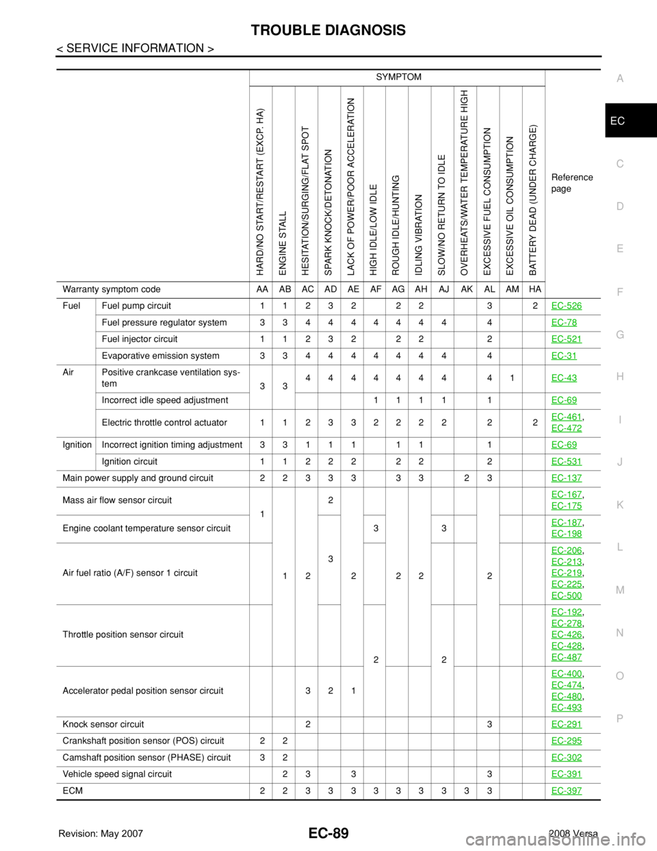
1 - 6: The numbers refer to the order of inspection.
(continued on next page)
SYSTEM — ENGINE MECHANICAL & OTHER
Intake valve timing control solenoid valve cir-
cuit32 13223 3EC-162
Park/neutral position (PNP) switch circuit 3 3 3 3 3EC-405
Refrigerant pressure sensor circuit 2 3 3 4EC-541
Electrical load signal circuit 3EC-519
Air conditioner circuit 223333333 3 2MTC-22
ABS actuator and electric unit (control unit) 4BRC-8
SYMPTOM
Reference
page
HARD/NO START/RESTART (EXCP. HA)
ENGINE STALL
HESITATION/SURGING/FLAT SPOT
SPARK KNOCK/DETONATION
LACK OF POWER/POOR ACCELERATION
HIGH IDLE/LOW IDLE
ROUGH IDLE/HUNTING
IDLING VIBRATION
SLOW/NO RETURN TO IDLE
OVERHEATS/WATER TEMPERATURE HIGH
EXCESSIVE FUEL CONSUMPTION
EXCESSIVE OIL CONSUMPTION
BATTERY DEAD (UNDER CHARGE)
Warranty symptom code AA AB AC AD AE AF AG AH AJ AK AL AM HA
Fuel Fuel tank
5
5FL-9
Fuel piping 5 5 5 5 5 5EM-33
Va p o r l o c k—
Valve deposit
5 555 55 5—
Poor fuel (Heavy weight gasoline,
Low octane)—
Page 1167 of 2771
TROUBLE DIAGNOSIS
EC-93
< SERVICE INFORMATION >
C
D
E
F
G
H
I
J
K
L
MA
EC
N
P O
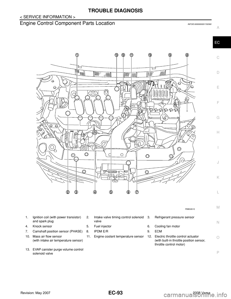
Engine Control Component Parts LocationINFOID:0000000001702590
1. Ignition coil (with power transistor)
and spark plug2. Intake valve timing control solenoid
valve3. Refrigerant pressure sensor
4. Knock sensor 5. Fuel injector 6. Cooling fan motor
7. Camshaft position sensor (PHASE) 8. IPDM E/R 9. ECM
10. Mass air flow sensor
(with intake air temperature sensor)11. Engine coolant temperature sensor 12. Electric throttle control actuator
(with built-in throttle position sensor,
throttle control motor)
13. EVAP canister purge volume control
solenoid valve
PBIB3261E
Page 1169 of 2771
TROUBLE DIAGNOSIS
EC-95
< SERVICE INFORMATION >
C
D
E
F
G
H
I
J
K
L
MA
EC
N
P O
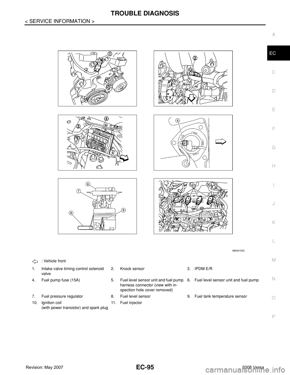
: Vehicle front
1. Intake valve timing control solenoid
valve2. Knock sensor 3. IPDM E/R
4. Fuel pump fuse (15A) 5. Fuel level sensor unit and fuel pump
harness connector (view with in-
spection hole cover removed)6. Fuel level sensor unit and fuel pump
7. Fuel pressure regulator 8. Fuel level sensor 9. Fuel tank temperature sensor
10. Ignition coil
(with power transistor) and spark plug11. Fuel injector
BBIA0725E
Page 1179 of 2771
![NISSAN TIIDA 2008 Service Repair Manual TROUBLE DIAGNOSIS
EC-105
< SERVICE INFORMATION >
C
D
E
F
G
H
I
J
K
L
MA
EC
N
P O
33 LG Throttle position sensor 1[Ignition switch: ON]
• Engine stopped
• Shift lever: D (A/T, CVT), 1st (M/T)
• A NISSAN TIIDA 2008 Service Repair Manual TROUBLE DIAGNOSIS
EC-105
< SERVICE INFORMATION >
C
D
E
F
G
H
I
J
K
L
MA
EC
N
P O
33 LG Throttle position sensor 1[Ignition switch: ON]
• Engine stopped
• Shift lever: D (A/T, CVT), 1st (M/T)
• A](/manual-img/5/57399/w960_57399-1178.png)
TROUBLE DIAGNOSIS
EC-105
< SERVICE INFORMATION >
C
D
E
F
G
H
I
J
K
L
MA
EC
N
P O
33 LG Throttle position sensor 1[Ignition switch: ON]
• Engine stopped
• Shift lever: D (A/T, CVT), 1st (M/T)
• Accelerator pedal: Fully releasedMore than 0.36V
[Ignition switch: ON]
• Engine stopped
• Shift lever: D (A/T, CVT), 1st (M/T)
• Accelerator pedal: Fully depressedLess than 4.75V
34 O Throttle position sensor 2[Ignition switch: ON]
• Engine stopped
• Shift lever: D (A/T, CVT), 1st (M/T)
• Accelerator pedal: Fully releasedLess than 4.75V
[Ignition switch: ON]
• Engine stopped
• Shift lever: D (A/T, CVT), 1st (M/T)
• Accelerator pedal: Fully depressedMore than 0.36V
36 YSensor ground
(Throttle position sensor)[Engine is running]
•Warm-up condition
• Idle speedApproximately 0V
37 W Knock sensor[Engine is running]
• Idle speedApproximately 2.5V
38 PEngine coolant temperature
sensor[Engine is running]Approximately 0 - 4.8V
Output voltage varies with en-
gine coolant temperature.
40 —Sensor ground
(Knock sensor)[Engine is running]
•Warm-up condition
• Idle speedApproximately 0V
41 GR Refrigerant pressure sensor[Engine is running]
•Warm-up condition
• Both A/C switch and blower fan switch: ON
(Compressor operates.)1.0 - 4.0V
42 VEVAP control system pres-
sure sensor[Ignition switch: ON]Approximately 1.8 - 4.8V
43 PFuel tank temperature sen-
sor[Engine is running]Approximately 0 - 4.8V
Output voltage varies with fuel
tank temperature
44 BSensor ground
(Engine coolant temperature
sensor)[Engine is running]
•Warm-up condition
• Idle speedApproximately 0V
45 G Mass air flow sensor[Engine is running]
•Warm-up condition
• Idle speed0.8 - 1.1V
[Engine is running]
•Warm-up condition
• Engine speed: 2,500 rpm1.4 - 1.7V
46 VIntake air temperature
sensor[Engine is running]Approximately 0 - 4.8V
Output voltage varies with intake
air temperature.
48 BRSensor ground
(Refrigerant pressure sen-
sor)[Engine is running]
•Warm-up condition
• Idle speed
Approximately 0V
49 W A/F sensor 1[Engine is running]
•Warm-up condition
• Engine speed: 2,000 rpmApproximately 1.8V
Output voltage varies with air fuel
ratio. TERMI-
NAL
NO.WIRE
COLORITEM CONDITION DATA (DC Voltage)