Page 1095 of 2771
PREPARATION
EC-21
< SERVICE INFORMATION >
C
D
E
F
G
H
I
J
K
L
MA
EC
N
P O
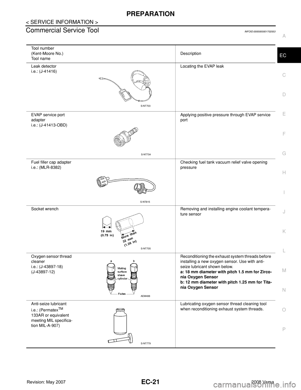
Commercial Service ToolINFOID:0000000001702553
Tool number
(Kent-Moore No.)
Tool nameDescription
Leak detector
i.e.: (J-41416)Locating the EVAP leak
EVAP service port
adapter
i.e.: (J-41413-OBD)Applying positive pressure through EVAP service
port
Fuel filler cap adapter
i.e.: (MLR-8382)Checking fuel tank vacuum relief valve opening
pressure
Socket wrench Removing and installing engine coolant tempera-
ture sensor
Oxygen sensor thread
cleaner
i.e.: (J-43897-18)
(J-43897-12)Reconditioning the exhaust system threads before
installing a new oxygen sensor. Use with anti-
seize lubricant shown below.
a: 18 mm diameter with pitch 1.5 mm for Zirco-
nia Oxygen Sensor
b: 12 mm diameter with pitch 1.25 mm for Tita-
nia Oxygen Sensor
Anti-seize lubricant
i.e.: (Permatex
TM
133AR or equivalent
meeting MIL specifica-
tion MIL-A-907)Lubricating oxygen sensor thread cleaning tool
when reconditioning exhaust system threads.
S-NT703
S-NT704
S-NT815
S-NT705
AEM488
S-NT779
Page 1108 of 2771
EC-34
< SERVICE INFORMATION >
EVAPORATIVE EMISSION SYSTEM
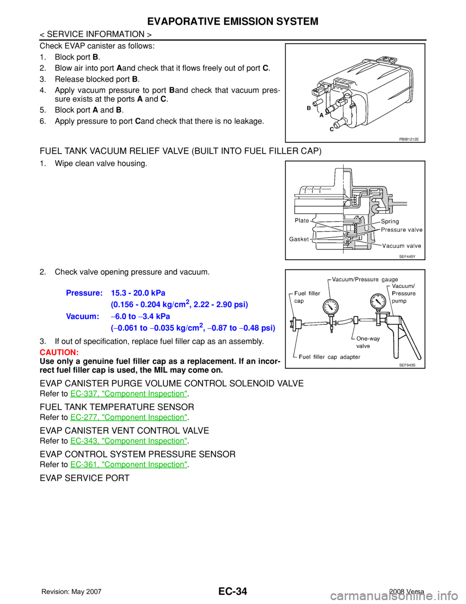
Check EVAP canister as follows:
1. Block port B.
2. Blow air into port Aand check that it flows freely out of port C.
3. Release blocked port B.
4. Apply vacuum pressure to port Band check that vacuum pres-
sure exists at the ports A and C.
5. Block port A and B.
6. Apply pressure to port Cand check that there is no leakage.
FUEL TANK VACUUM RELIEF VALVE (BUILT INTO FUEL FILLER CAP)
1. Wipe clean valve housing.
2. Check valve opening pressure and vacuum.
3. If out of specification, replace fuel filler cap as an assembly.
CAUTION:
Use only a genuine fuel filler cap as a replacement. If an incor-
rect fuel filler cap is used, the MIL may come on.
EVAP CANISTER PURGE VOLUME CONTROL SOLENOID VALVE
Refer to EC-337, "Component Inspection".
FUEL TANK TEMPERATURE SENSOR
Refer to EC-277, "Component Inspection".
EVAP CANISTER VENT CONTROL VALVE
Refer to EC-343, "Component Inspection".
EVAP CONTROL SYSTEM PRESSURE SENSOR
Refer to EC-361, "Component Inspection".
EVAP SERVICE PORT
PBIB1212E
SEF445Y
Pressure: 15.3 - 20.0 kPa
(0.156 - 0.204 kg/cm
2, 2.22 - 2.90 psi)
Vacuum:−6.0 to −3.4 kPa
(−0.061 to −0.035 kg/cm
2, −0.87 to −0.48 psi)
SEF943S
Page 1109 of 2771
EVAPORATIVE EMISSION SYSTEM
EC-35
< SERVICE INFORMATION >
C
D
E
F
G
H
I
J
K
L
MA
EC
N
P O
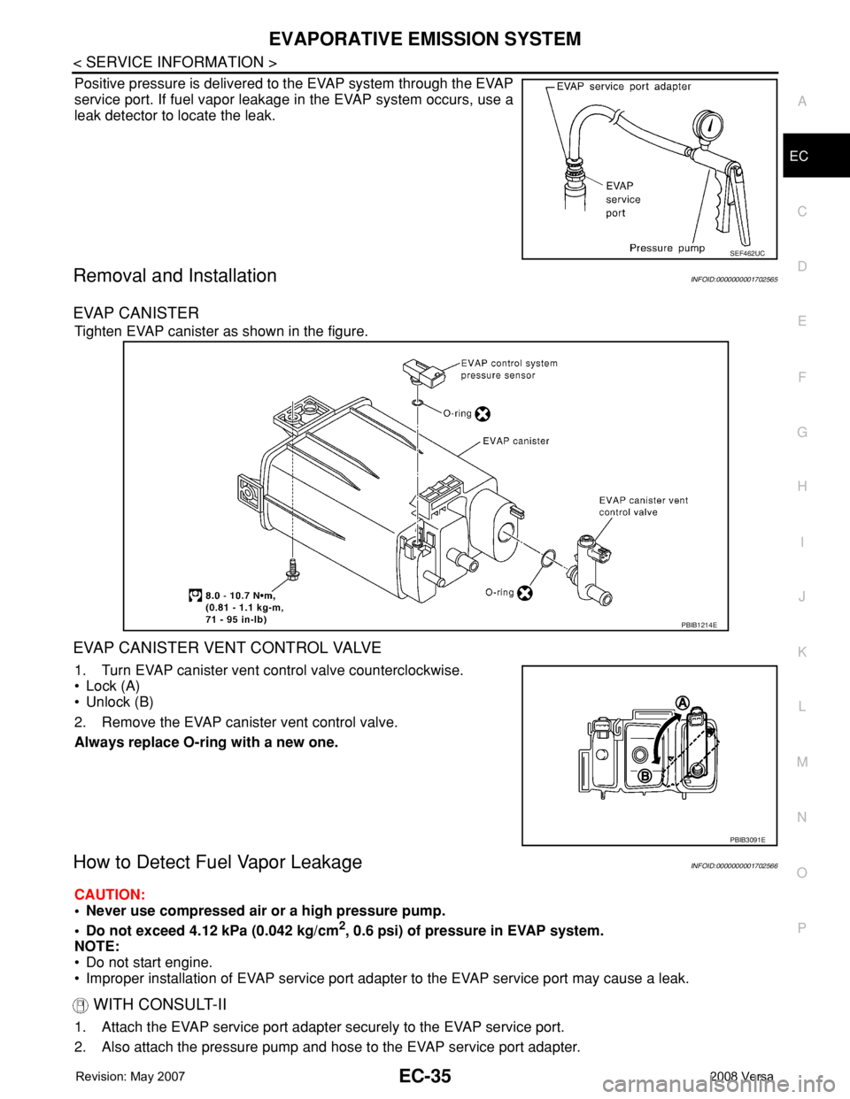
Positive pressure is delivered to the EVAP system through the EVAP
service port. If fuel vapor leakage in the EVAP system occurs, use a
leak detector to locate the leak.
Removal and InstallationINFOID:0000000001702565
EVAP CANISTER
Tighten EVAP canister as shown in the figure.
EVAP CANISTER VENT CONTROL VALVE
1. Turn EVAP canister vent control valve counterclockwise.
• Lock (A)
• Unlock (B)
2. Remove the EVAP canister vent control valve.
Always replace O-ring with a new one.
How to Detect Fuel Vapor LeakageINFOID:0000000001702566
CAUTION:
• Never use compressed air or a high pressure pump.
• Do not exceed 4.12 kPa (0.042 kg/cm
2, 0.6 psi) of pressure in EVAP system.
NOTE:
• Do not start engine.
• Improper installation of EVAP service port adapter to the EVAP service port may cause a leak.
WITH CONSULT-II
1. Attach the EVAP service port adapter securely to the EVAP service port.
2. Also attach the pressure pump and hose to the EVAP service port adapter.
SEF462UC
PBIB1214E
PBIB3091E
Page 1112 of 2771
EC-38
< SERVICE INFORMATION >
ON BOARD REFUELING VAPOR RECOVERY (ORVR)
ON BOARD REFUELING VAPOR RECOVERY (ORVR)
System DescriptionINFOID:0000000001702567
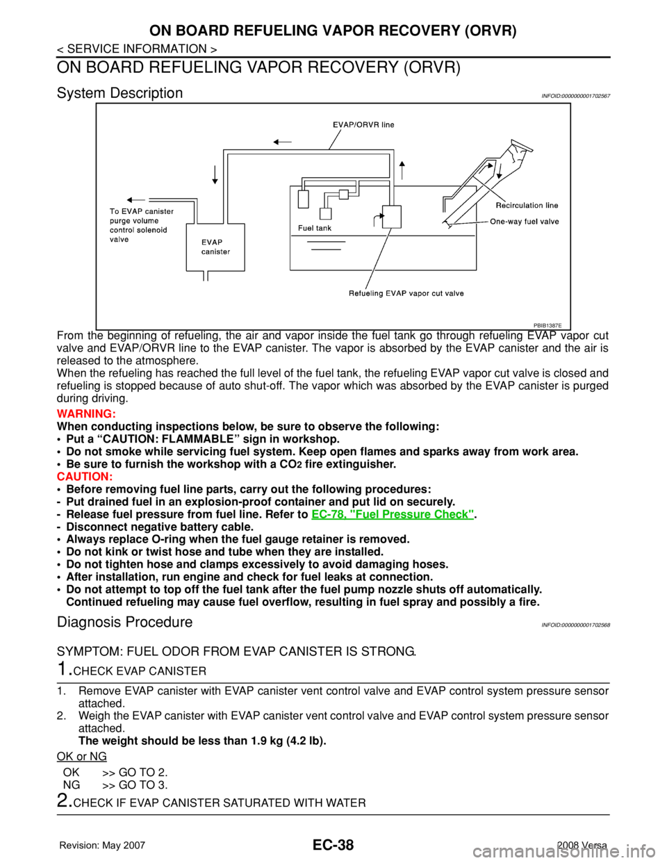
From the beginning of refueling, the air and vapor inside the fuel tank go through refueling EVAP vapor cut
valve and EVAP/ORVR line to the EVAP canister. The vapor is absorbed by the EVAP canister and the air is
released to the atmosphere.
When the refueling has reached the full level of the fuel tank, the refueling EVAP vapor cut valve is closed and
refueling is stopped because of auto shut-off. The vapor which was absorbed by the EVAP canister is purged
during driving.
WARNING:
When conducting inspections below, be sure to observe the following:
• Put a “CAUTION: FLAMMABLE” sign in workshop.
• Do not smoke while servicing fuel system. Keep open flames and sparks away from work area.
• Be sure to furnish the workshop with a CO
2 fire extinguisher.
CAUTION:
• Before removing fuel line parts, carry out the following procedures:
- Put drained fuel in an explosion-proof container and put lid on securely.
- Release fuel pressure from fuel line. Refer to EC-78, "
Fuel Pressure Check".
- Disconnect negative battery cable.
• Always replace O-ring when the fuel gauge retainer is removed.
• Do not kink or twist hose and tube when they are installed.
• Do not tighten hose and clamps excessively to avoid damaging hoses.
• After installation, run engine and check for fuel leaks at connection.
• Do not attempt to top off the fuel tank after the fuel pump nozzle shuts off automatically.
Continued refueling may cause fuel overflow, resulting in fuel spray and possibly a fire.
Diagnosis ProcedureINFOID:0000000001702568
SYMPTOM: FUEL ODOR FROM EVAP CANISTER IS STRONG.
1.CHECK EVAP CANISTER
1. Remove EVAP canister with EVAP canister vent control valve and EVAP control system pressure sensor
attached.
2. Weigh the EVAP canister with EVAP canister vent control valve and EVAP control system pressure sensor
attached.
The weight should be less than 1.9 kg (4.2 lb).
OK or NG
OK >> GO TO 2.
NG >> GO TO 3.
2.CHECK IF EVAP CANISTER SATURATED WITH WATER
PBIB1387E
Page 1113 of 2771
ON BOARD REFUELING VAPOR RECOVERY (ORVR)
EC-39
< SERVICE INFORMATION >
C
D
E
F
G
H
I
J
K
L
MA
EC
N
P O
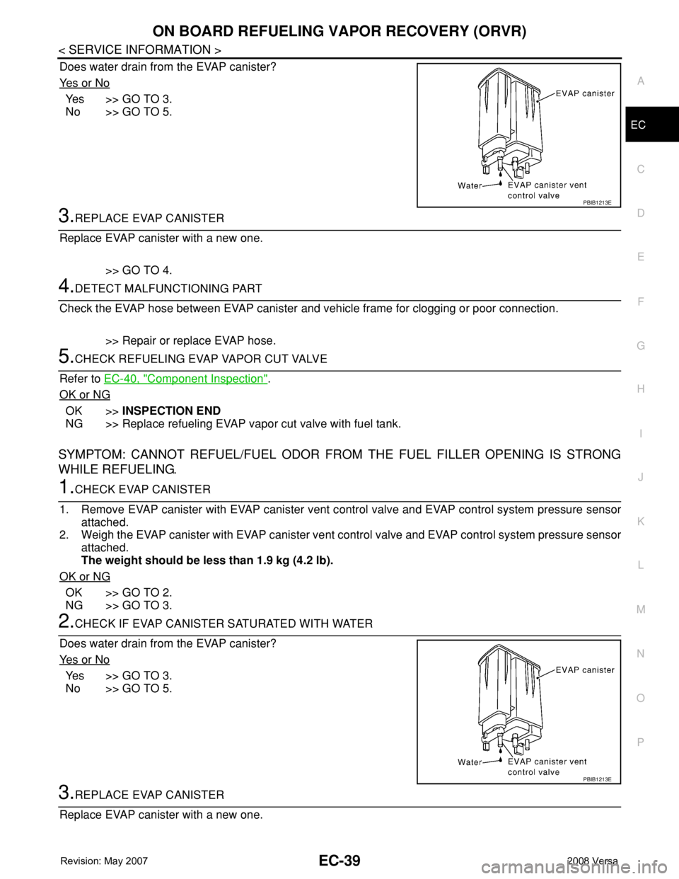
Does water drain from the EVAP canister?
Ye s o r N o
Yes >> GO TO 3.
No >> GO TO 5.
3.REPLACE EVAP CANISTER
Replace EVAP canister with a new one.
>> GO TO 4.
4.DETECT MALFUNCTIONING PART
Check the EVAP hose between EVAP canister and vehicle frame for clogging or poor connection.
>> Repair or replace EVAP hose.
5.CHECK REFUELING EVAP VAPOR CUT VALVE
Refer to EC-40, "
Component Inspection".
OK or NG
OK >>INSPECTION END
NG >> Replace refueling EVAP vapor cut valve with fuel tank.
SYMPTOM: CANNOT REFUEL/FUEL ODOR FROM THE FUEL FILLER OPENING IS STRONG
WHILE REFUELING.
1.CHECK EVAP CANISTER
1. Remove EVAP canister with EVAP canister vent control valve and EVAP control system pressure sensor
attached.
2. Weigh the EVAP canister with EVAP canister vent control valve and EVAP control system pressure sensor
attached.
The weight should be less than 1.9 kg (4.2 lb).
OK or NG
OK >> GO TO 2.
NG >> GO TO 3.
2.CHECK IF EVAP CANISTER SATURATED WITH WATER
Does water drain from the EVAP canister?
Ye s o r N o
Yes >> GO TO 3.
No >> GO TO 5.
3.REPLACE EVAP CANISTER
Replace EVAP canister with a new one.
PBIB1213E
PBIB1213E
Page 1115 of 2771
ON BOARD REFUELING VAPOR RECOVERY (ORVR)
EC-41
< SERVICE INFORMATION >
C
D
E
F
G
H
I
J
K
L
MA
EC
N
P O
1. Remove fuel tank. Refer to FL-9.
2. Drain fuel from the tank as follows:
a. Remove fuel feed hose located on the fuel gauge retainer.
b. Connect a spare fuel hose, one side to fuel gauge retainer where the hose was removed and the other
side to a fuel container.
c. Drain fuel using “FUEL PUMP RELAY” in “ACTIVE TEST” mode with CONSULT-II.
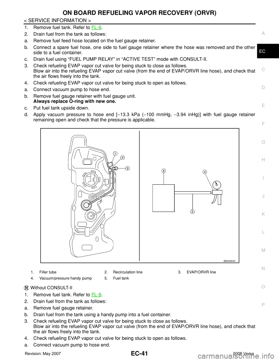
3. Check refueling EVAP vapor cut valve for being stuck to close as follows.
Blow air into the refueling EVAP vapor cut valve (from the end of EVAP/ORVR line hose), and check that
the air flows freely into the tank.
4. Check refueling EVAP vapor cut valve for being stuck to open as follows.
a. Connect vacuum pump to hose end.
b. Remove fuel gauge retainer with fuel gauge unit.
Always replace O-ring with new one.
c. Put fuel tank upside down.
d. Apply vacuum pressure to hose end [−13.3 kPa (−100 mmHg, −3.94 inHg)] with fuel gauge retainer
remaining open and check that the pressure is applicable.
Without CONSULT-II
1. Remove fuel tank. Refer to FL-9.
2. Drain fuel from the tank as follows:
a. Remove fuel gauge retainer.
b. Drain fuel from the tank using a handy pump into a fuel container.
3. Check refueling EVAP vapor cut valve for being stuck to close as follows.
Blow air into the refueling EVAP vapor cut valve (from the end of EVAP/ORVR line hose), and check that
the air flows freely into the tank.
4. Check refueling EVAP vapor cut valve for being stuck to open as follows.
a. Connect vacuum pump to hose end.
1. Filler tube 2. Recirculation line 3. EVAP/ORVR line
4. Vacuum/pressure handy pump 5. Fuel tank
BBIA0694E
Page 1116 of 2771
EC-42
< SERVICE INFORMATION >
ON BOARD REFUELING VAPOR RECOVERY (ORVR)
b. Remove fuel gauge retainer with fuel gauge unit.
Always replace O-ring with new one.
c. Put fuel tank upside down.
d. Apply vacuum pressure to hose end [−13.3 kPa (−100 mmHg, −3.94 inHg)] with fuel gauge retainer
remaining open and check that the pressure is applicable.
1. Filler tube 2. Recirculation line 3. EVAP/ORVR line
4. Vacuum/pressure handy pump 5. Fuel tank
BBIA0694E
Page 1152 of 2771
EC-78
< SERVICE INFORMATION >
BASIC SERVICE PROCEDURE
b. Fully release the accelerator pedal.
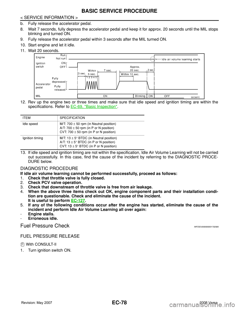
8. Wait 7 seconds, fully depress the accelerator pedal and keep it for approx. 20 seconds until the MIL stops
blinking and turned ON.
9. Fully release the accelerator pedal within 3 seconds after the MIL turned ON.
10. Start engine and let it idle.
11. Wait 20 seconds.
12. Rev up the engine two or three times and make sure that idle speed and ignition timing are within the
specifications. Refer to EC-69, "
Basic Inspection".
13. If idle speed and ignition timing are not within the specification, Idle Air Volume Learning will not be carried
out successfully. In this case, find the cause of the incident by referring to the DIAGNOSTIC PROCE-
DURE below.
DIAGNOSTIC PROCEDURE
If idle air volume learning cannot be performed successfully, proceed as follows:
1.Check that throttle valve is fully closed.
2.Check PCV valve operation.
3.Check that downstream of throttle valve is free from air leakage.
4.When the above three items check out OK, engine component parts and their installation condi-
tion are questionable. Check and eliminate the cause of the incident.
It is useful to perform EC-127
.
5.If any of the following conditions occur after the engine has started, eliminate the cause of the
incident and perform Idle Air Volume Learning all over again:
-Engine stalls.
-Erroneous idle.
Fuel Pressure CheckINFOID:0000000001702585
FUEL PRESSURE RELEASE
With CONSULT-II
1. Turn ignition switch ON.
ITEM SPECIFICATION
Idle speed M/T: 700 ± 50 rpm (in Neutral position)
A/T: 700 ± 50 rpm (in P or N position)
CVT: 700 ± 50 rpm (in P or N position)
Ignition timing M/T: 13 ± 5° BTDC (in Neutral position)
A/T: 13 ± 5° BTDC (in P or N position)
CVT: 13 ± 5° BTDC (in P or N position)
SEC897C