Page 1529 of 2771
DTC P1805 BRAKE SWITCH
EC-455
< SERVICE INFORMATION >
C
D
E
F
G
H
I
J
K
L
MA
EC
N
P O
>> Repair open circuit or short to ground or short to power in harness or connectors.
4.CHECK STOP LAMP SWITCH INPUT SIGNAL CIRCUIT FOR OPEN AND SHORT
1. Disconnect stop lamp switch (1) harness connector.
2. Disconnect ECM harness connector.
3. Check harness continuity between stop lamp switch terminal 2 and ECM terminal 99.
Refer to Wiring Diagram.
4. Also check harness for short to ground and short to power.
OK or NG
OK >> GO TO 5.
NG >> Repair open circuit or short to ground or short to power in harness connectors.
5.CHECK STOP LAMP SWITCH
Refer to EC-455, "
Component Inspection".
OK or NG
OK >> GO TO 6.
NG >> Replace stop lamp switch.
6.CHECK INTERMITTENT INCIDENT
Refer to EC-136
.
>>INSPECTION END
Component InspectionINFOID:0000000001702984
STOP LAMP SWITCH
1. Turn ignition switch OFF.
2. Disconnect stop lamp switch harness connector.
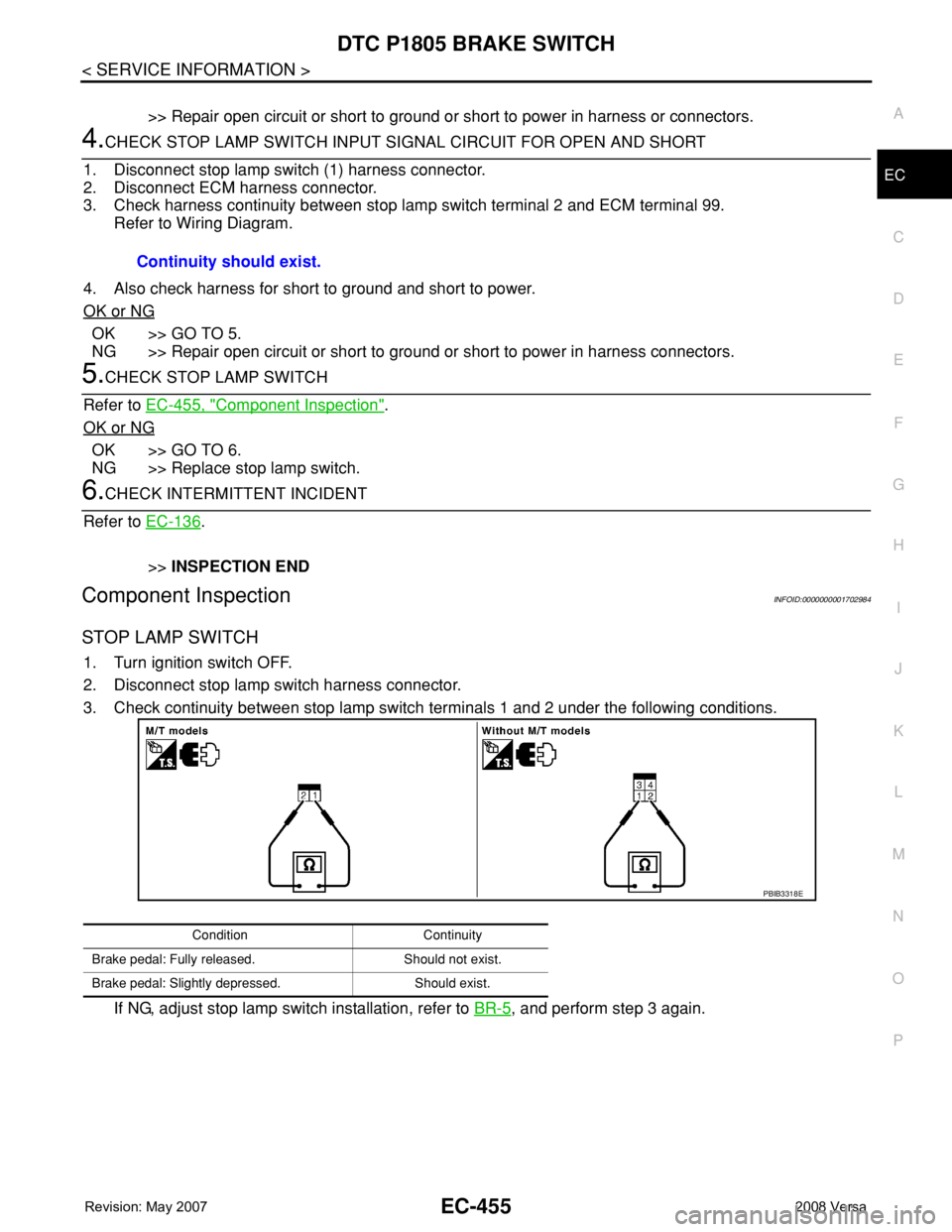
3. Check continuity between stop lamp switch terminals 1 and 2 under the following conditions.
If NG, adjust stop lamp switch installation, refer to BR-5
, and perform step 3 again. Continuity should exist.
Condition Continuity
Brake pedal: Fully released. Should not exist.
Brake pedal: Slightly depressed. Should exist.
PBIB3318E
Page 1532 of 2771
EC-458
< SERVICE INFORMATION >
DTC P2100, P2103 THROTTLE CONTROL MOTOR RELAY
Wiring Diagram
INFOID:0000000001702989
Specification data are reference values and are measured between each terminal and ground.
Pulse signal is measured by CONSULT-II.
CAUTION:
BBWA2644E
Page 1533 of 2771
DTC P2100, P2103 THROTTLE CONTROL MOTOR RELAY
EC-459
< SERVICE INFORMATION >
C
D
E
F
G
H
I
J
K
L
MA
EC
N
P O
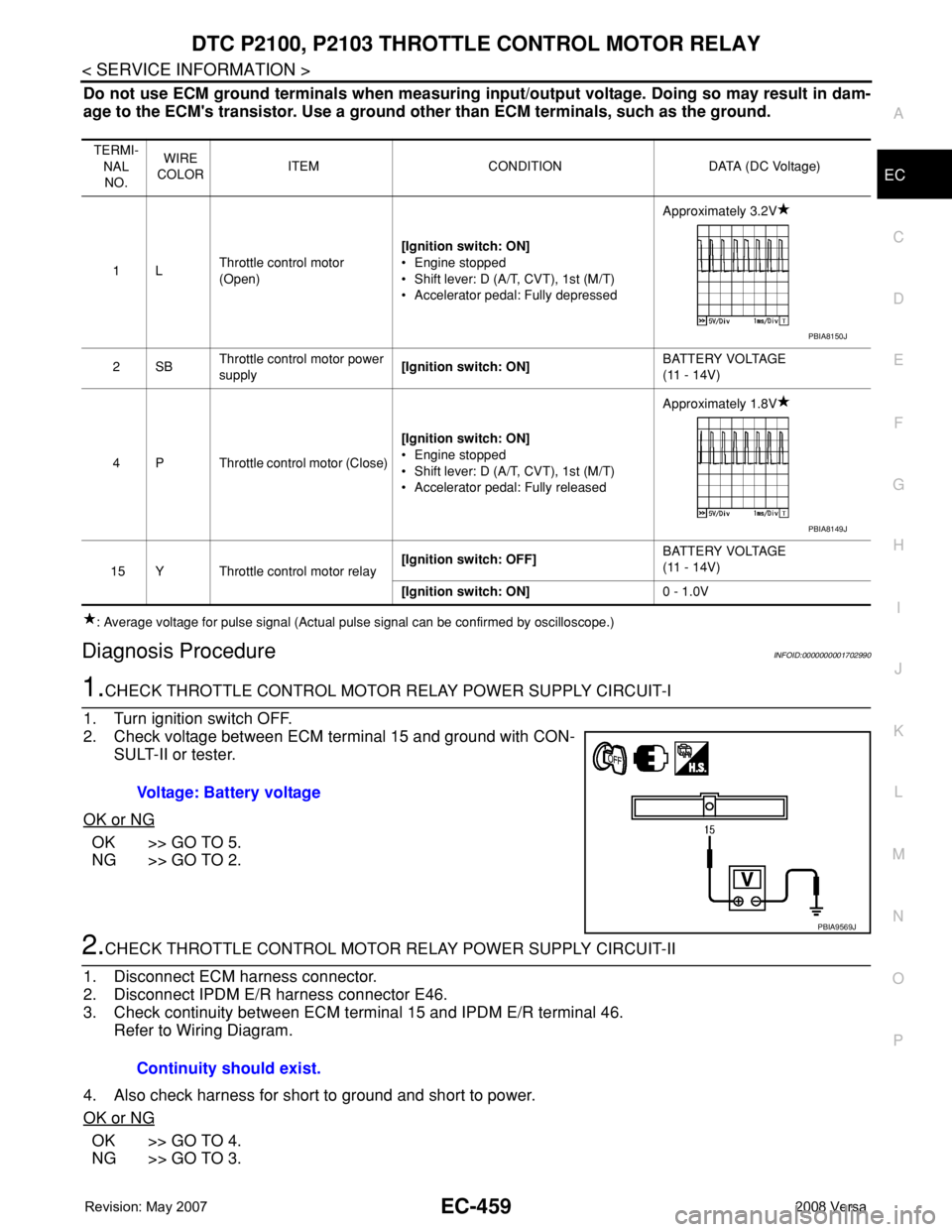
Do not use ECM ground terminals when measuring input/output voltage. Doing so may result in dam-
age to the ECM's transistor. Use a ground other than ECM terminals, such as the ground.
: Average voltage for pulse signal (Actual pulse signal can be confirmed by oscilloscope.)
Diagnosis ProcedureINFOID:0000000001702990
1.CHECK THROTTLE CONTROL MOTOR RELAY POWER SUPPLY CIRCUIT-I
1. Turn ignition switch OFF.
2. Check voltage between ECM terminal 15 and ground with CON-
SULT-II or tester.
OK or NG
OK >> GO TO 5.
NG >> GO TO 2.
2.CHECK THROTTLE CONTROL MOTOR RELAY POWER SUPPLY CIRCUIT-II
1. Disconnect ECM harness connector.
2. Disconnect IPDM E/R harness connector E46.
3. Check continuity between ECM terminal 15 and IPDM E/R terminal 46.
Refer to Wiring Diagram.
4. Also check harness for short to ground and short to power.
OK or NG
OK >> GO TO 4.
NG >> GO TO 3.
TERMI-
NAL
NO.WIRE
COLORITEM CONDITION DATA (DC Voltage)
1LThrottle control motor
(Open)[Ignition switch: ON]
• Engine stopped
• Shift lever: D (A/T, CVT), 1st (M/T)
• Accelerator pedal: Fully depressedApproximately 3.2V
2SBThrottle control motor power
supply[Ignition switch: ON]BATTERY VOLTAGE
(11 - 14V)
4 P Throttle control motor (Close)[Ignition switch: ON]
• Engine stopped
• Shift lever: D (A/T, CVT), 1st (M/T)
• Accelerator pedal: Fully releasedApproximately 1.8V
15 Y Throttle control motor relay[Ignition switch: OFF]BATTERY VOLTAGE
(11 - 14V)
[Ignition switch: ON]0 - 1.0V
PBIA8150J
PBIA8149J
Voltage: Battery voltage
PBIA9569J
Continuity should exist.
Page 1534 of 2771
EC-460
< SERVICE INFORMATION >
DTC P2100, P2103 THROTTLE CONTROL MOTOR RELAY
3.DETECT MALFUNCTIONING PART
Check the following.
• Harness connectors E8, F8
• Harness for open or short between ECM and IPDM E/R
>> Repair open circuit or short to ground or short to power in harness or connectors.
4.CHECK FUSE
1. Disconnect 15A fuse.
2. Check 15A fuse for blown.
OK or NG
OK >> GO TO 8.
NG >> Replace 15A fuse.
5.CHECK THROTTLE CONTROL MOTOR RELAY INPUT SIGNAL CIRCUIT-I
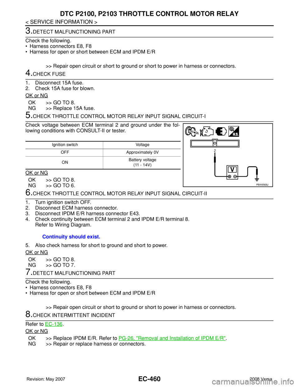
Check voltage between ECM terminal 2 and ground under the fol-
lowing conditions with CONSULT-II or tester.
OK or NG
OK >> GO TO 8.
NG >> GO TO 6.
6.CHECK THROTTLE CONTROL MOTOR RELAY INPUT SIGNAL CIRCUIT-II
1. Turn ignition switch OFF.
2. Disconnect ECM harness connector.
3. Disconnect IPDM E/R harness connector E43.
4. Check continuity between ECM terminal 2 and IPDM E/R terminal 8.
Refer to Wiring Diagram.
5. Also check harness for short to ground and short to power.
OK or NG
OK >> GO TO 8.
NG >> GO TO 7.
7.DETECT MALFUNCTIONING PART
Check the following.
• Harness connectors E8, F8
• Harness for open or short between ECM and IPDM E/R
>> Repair open circuit or short to ground or short to power in harness or connectors.
8.CHECK INTERMITTENT INCIDENT
Refer to EC-136
.
OK or NG
OK >> Replace IPDM E/R. Refer to PG-26, "Removal and Installation of IPDM E/R".
NG >> Repair or replace harness or connectors.
Ignition switch Voltage
OFF Approximately 0V
ONBattery voltage
(11 - 14V)
PBIA9568J
Continuity should exist.
Page 1536 of 2771
EC-462
< SERVICE INFORMATION >
DTC P2101 ELECTRIC THROTTLE CONTROL FUNCTION
Wiring Diagram
INFOID:0000000001702994
Specification data are reference values and are measured between each terminal and ground.
Pulse signal is measured by CONSULT-II.
CAUTION:
BBWA2643E
Page 1538 of 2771
EC-464
< SERVICE INFORMATION >
DTC P2101 ELECTRIC THROTTLE CONTROL FUNCTION
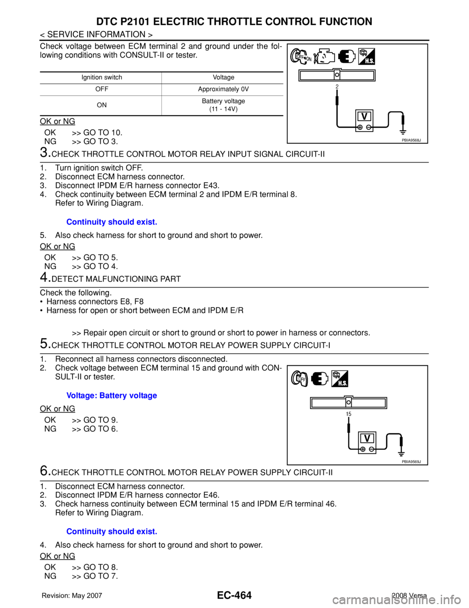
Check voltage between ECM terminal 2 and ground under the fol-
lowing conditions with CONSULT-II or tester.
OK or NG
OK >> GO TO 10.
NG >> GO TO 3.
3.CHECK THROTTLE CONTROL MOTOR RELAY INPUT SIGNAL CIRCUIT-II
1. Turn ignition switch OFF.
2. Disconnect ECM harness connector.
3. Disconnect IPDM E/R harness connector E43.
4. Check continuity between ECM terminal 2 and IPDM E/R terminal 8.
Refer to Wiring Diagram.
5. Also check harness for short to ground and short to power.
OK or NG
OK >> GO TO 5.
NG >> GO TO 4.
4.DETECT MALFUNCTIONING PART
Check the following.
• Harness connectors E8, F8
• Harness for open or short between ECM and IPDM E/R
>> Repair open circuit or short to ground or short to power in harness or connectors.
5.CHECK THROTTLE CONTROL MOTOR RELAY POWER SUPPLY CIRCUIT-I
1. Reconnect all harness connectors disconnected.
2. Check voltage between ECM terminal 15 and ground with CON-
SULT-II or tester.
OK or NG
OK >> GO TO 9.
NG >> GO TO 6.
6.CHECK THROTTLE CONTROL MOTOR RELAY POWER SUPPLY CIRCUIT-II
1. Disconnect ECM harness connector.
2. Disconnect IPDM E/R harness connector E46.
3. Check harness continuity between ECM terminal 15 and IPDM E/R terminal 46.
Refer to Wiring Diagram.
4. Also check harness for short to ground and short to power.
OK or NG
OK >> GO TO 8.
NG >> GO TO 7.
Ignition switch Voltage
OFF Approximately 0V
ONBattery voltage
(11 - 14V)
PBIA9568J
Continuity should exist.
Voltage: Battery voltage
PBIA9569J
Continuity should exist.
Page 1539 of 2771
DTC P2101 ELECTRIC THROTTLE CONTROL FUNCTION
EC-465
< SERVICE INFORMATION >
C
D
E
F
G
H
I
J
K
L
MA
EC
N
P O
7.DETECT MALFUNCTIONING PART
Check the following.
• Harness connectors E8, F8
• Harness for open or short between ECM and IPDM E/R
>> Repair open circuit or short to ground or short to power in harness or connectors.
8.CHECK FUSE
1. Disconnect 15A fuse.
2. Check 15A fuse for blown.
OK or NG
OK >> GO TO 9.
NG >> Replace 15A fuse.
9.CHECK INTERMITTENT INCIDENT
Refer to EC-136
.
OK or NG
OK >> Replace IPDM E/R. Refer to PG-26, "Removal and Installation of IPDM E/R".
NG >> Repair or replace harness or connectors.
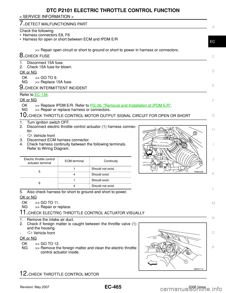
10.CHECK THROTTLE CONTROL MOTOR OUTPUT SIGNAL CIRCUIT FOR OPEN OR SHORT
1. Turn ignition switch OFF.
2. Disconnect electric throttle control actuator (1) harness connec-
tor.
- : Vehicle front
3. Disconnect ECM harness connector.
4. Check harness continuity between the following terminals.
Refer to Wiring Diagram.
5. Also check harness for short to ground and short to power.
OK or NG
OK >> GO TO 11.
NG >> Repair or replace.
11 .CHECK ELECTRIC THROTTLE CONTROL ACTUATOR VISUALLY
1. Remove the intake air duct.
2. Check if foreign matter is caught between the throttle valve (1)
and the housing.
- : Vehicle front
OK or NG
OK >> GO TO 12.
NG >> Remove the foreign matter and clean the electric throttle
control actuator inside.
12.CHECK THROTTLE CONTROL MOTOR
Electric throttle control
actuator terminalECM terminal Continuity
51 Should not exist.
4 Should exist.
61 Should exist.
4 Should not exist.
PBIB3325E
BBIA0711E
Page 1542 of 2771
EC-468
< SERVICE INFORMATION >
DTC P2118 THROTTLE CONTROL MOTOR
Wiring Diagram
INFOID:0000000001703001
Specification data are reference values and are measured between each terminal and ground.
Pulse signal is measured by CONSULT-II.
CAUTION:
BBWA2645E