Page 1421 of 2771
DTC P0448 EVAP CANISTER VENT CONTROL VALVE
EC-347
< SERVICE INFORMATION >
C
D
E
F
G
H
I
J
K
L
MA
EC
N
P O
Wiring DiagramINFOID:0000000001702855
Specification data are reference values and are measured between each terminal and ground.
CAUTION:
Do not use ECM ground terminals when measuring input/output voltage. Doing so may result in dam-
age to the ECM's transistor. Use a ground other than ECM terminals, such as the ground.
BBWA3072E
Page 1427 of 2771
DTC P0451 EVAP CONTROL SYSTEM PRESSURE SENSOR
EC-353
< SERVICE INFORMATION >
C
D
E
F
G
H
I
J
K
L
MA
EC
N
P O
OK or NG
OK >> GO TO 4.
NG >> Repair short to ground or short to power in harness or connectors.
4.CHECK COMPONENTS
Check the following.
• Refrigerant pressure sensor (Refer to MTC-22
.)
• Crankshaft position sensor (POS) (Refer to EC-301, "
Component Inspection".)
OK or NG
OK >> GO TO 5.
NG >> Replace malfunctioning components.
5.CHECK APP SENSOR
Refer to EC-485, "
Component Inspection".
OK or NG
OK >> GO TO 7.
NG >> GO TO 6.
6.REPLACE ACCELERATOR PEDAL ASSEMBLY
1. Replace accelerator pedal assembly.
2. Perform EC-76, "
Accelerator Pedal Released Position Learning".
3. Perform EC-76, "
Throttle Valve Closed Position Learning".
4. Perform EC-76, "
Idle Air Volume Learning".
>>INSPECTION END
7.CHECK EVAP CONTROL SYSTEM PRESSURE SENSOR
Refer to EC-353, "
Component Inspection".
OK or NG
OK >> GO TO 8.
NG >> Replace EVAP control system pressure sensor.
8.CHECK INTERMITTENT INCIDENT
Refer to EC-136
.
For wiring diagram, refer to EC-357, "
Wiring Diagram".
>>INSPECTION END
Component InspectionINFOID:0000000001702863
EVAP CONTROL SYSTEM PRESSURE SENSOR
1. Remove EVAP control system pressure sensor with its harness connector connected from EVAP canister.
Always replace O-ring with a new one.
2. Install a vacuum pump to EVAP control system pressure sensor.
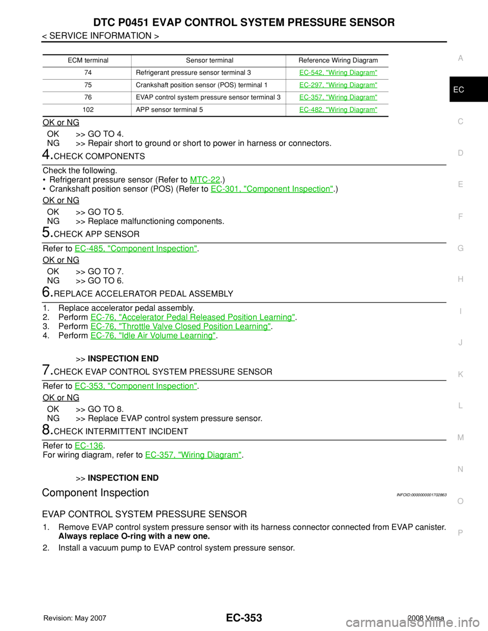
ECM terminal Sensor terminal Reference Wiring Diagram
74 Refrigerant pressure sensor terminal 3EC-542, "
Wiring Diagram"
75 Crankshaft position sensor (POS) terminal 1EC-297, "Wiring Diagram"
76 EVAP control system pressure sensor terminal 3EC-357, "Wiring Diagram"
102 APP sensor terminal 5EC-482, "Wiring Diagram"
Page 1431 of 2771
DTC P0452 EVAP CONTROL SYSTEM PRESSURE SENSOR
EC-357
< SERVICE INFORMATION >
C
D
E
F
G
H
I
J
K
L
MA
EC
N
P O
Wiring DiagramINFOID:0000000001702868
Specification data are reference values and are measured between each terminal and ground.
CAUTION:
Do not use ECM ground terminals when measuring input/output voltage. Doing so may result in dam-
age to the ECM's transistor. Use a ground other than ECM terminals, such as the ground.
BBWA3073E
Page 1434 of 2771
EC-360
< SERVICE INFORMATION >
DTC P0452 EVAP CONTROL SYSTEM PRESSURE SENSOR
OK or NG
OK >> GO TO 8.
NG >> Repair short to ground or short to power in harness or connectors.
8.CHECK COMPONENTS
Check the following.
• Refrigerant pressure sensor (Refer to MTC-22
.)
• Crankshaft position sensor (POS) (Refer to EC-301, "
Component Inspection".)
OK or NG
OK >> GO TO 9.
NG >> Replace malfunctioning components.
9.CHECK APP SENSOR
Refer to EC-485, "
Component Inspection".
OK or NG
OK >> GO TO 11.
NG >> GO TO 10.
10.REPLACE ACCELERATOR PEDAL ASSEMBLY
1. Replace accelerator pedal assembly.
2. Perform EC-76, "
Accelerator Pedal Released Position Learning".
3. Perform EC-76, "
Throttle Valve Closed Position Learning".
4. Perform EC-76, "
Idle Air Volume Learning".
>>INSPECTION END
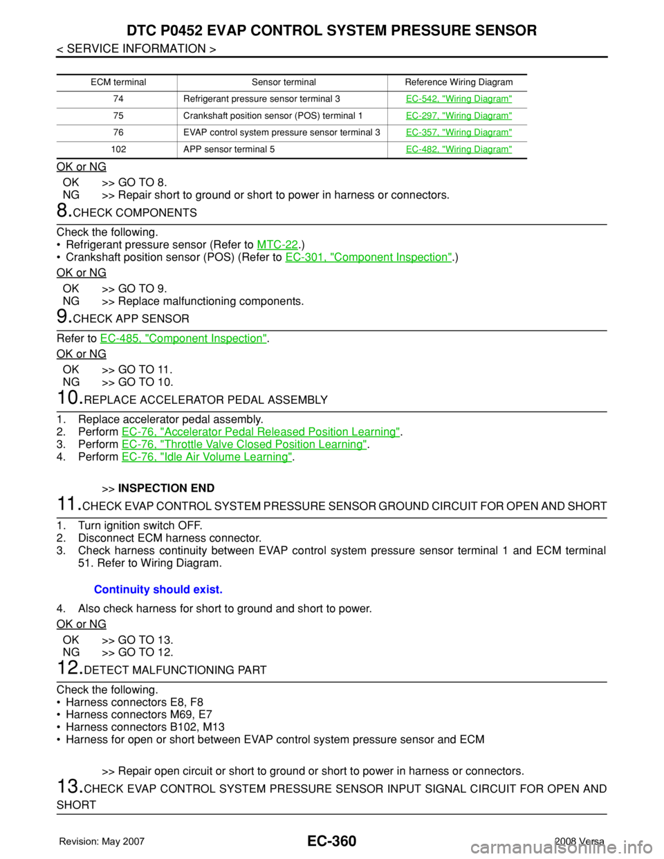
11 .CHECK EVAP CONTROL SYSTEM PRESSURE SENSOR GROUND CIRCUIT FOR OPEN AND SHORT
1. Turn ignition switch OFF.
2. Disconnect ECM harness connector.
3. Check harness continuity between EVAP control system pressure sensor terminal 1 and ECM terminal
51. Refer to Wiring Diagram.
4. Also check harness for short to ground and short to power.
OK or NG
OK >> GO TO 13.
NG >> GO TO 12.
12.DETECT MALFUNCTIONING PART
Check the following.
• Harness connectors E8, F8
• Harness connectors M69, E7
• Harness connectors B102, M13
• Harness for open or short between EVAP control system pressure sensor and ECM
>> Repair open circuit or short to ground or short to power in harness or connectors.
13.CHECK EVAP CONTROL SYSTEM PRESSURE SENSOR INPUT SIGNAL CIRCUIT FOR OPEN AND
SHORT
ECM terminal Sensor terminal Reference Wiring Diagram
74 Refrigerant pressure sensor terminal 3EC-542, "
Wiring Diagram"
75 Crankshaft position sensor (POS) terminal 1EC-297, "Wiring Diagram"
76 EVAP control system pressure sensor terminal 3EC-357, "Wiring Diagram"
102 APP sensor terminal 5EC-482, "Wiring Diagram"
Continuity should exist.
Page 1435 of 2771
DTC P0452 EVAP CONTROL SYSTEM PRESSURE SENSOR
EC-361
< SERVICE INFORMATION >
C
D
E
F
G
H
I
J
K
L
MA
EC
N
P O
1. Check harness continuity between ECM terminal 42 and EVAP control system pressure sensor terminal
2. Refer to Wiring Diagram.
2. Also check harness for short to ground and short to power.
OK or NG
OK >> GO TO 15.
NG >> GO TO 14.
14.DETECT MALFUNCTIONING PART
Check the following.
• Harness connectors E8, F8
• Harness connectors M69, E7
• Harness connectors B102, M13
• Harness for open or short between ECM and EVAP control system pressure sensor
>> Repair open circuit or short to ground or short to power in harness or connectors.
15.CHECK EVAP CONTROL SYSTEM PRESSURE SENSOR
Refer to EC-361, "
Component Inspection".
OK or NG
OK >> GO TO 16.
NG >> Replace EVAP control system pressure sensor.
16.CHECK INTERMITTENT INCIDENT
Refer to EC-136
.
>>INSPECTION END
Component InspectionINFOID:0000000001702870
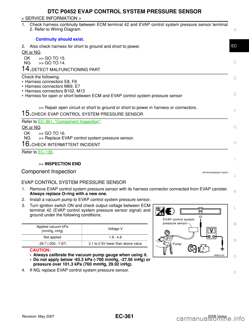
EVAP CONTROL SYSTEM PRESSURE SENSOR
1. Remove EVAP control system pressure sensor with its harness connector connected from EVAP canister.
Always replace O-ring with a new one.
2. Install a vacuum pump to EVAP control system pressure sensor.
3. Turn ignition switch ON and check output voltage between ECM
terminal 42 (EVAP control system pressure sensor signal) and
ground under the following conditions.
CAUTION:
• Always calibrate the vacuum pump gauge when using it.
• Do not apply below -93.3 kPa (-700 mmHg, -27.56 inHg) or
pressure over 101.3 kPa (760 mmHg, 29.92 inHg).
4. If NG, replace EVAP control system pressure sensor.Continuity should exist.
Applied vacuum kPa
(mmHg, inHg)Voltage V
Not applied 1.8 - 4.8
-26.7 (-200, -7.87) 2.1 to 2.5V lower than above value
PBIB3314E
Page 1438 of 2771
EC-364
< SERVICE INFORMATION >
DTC P0453 EVAP CONTROL SYSTEM PRESSURE SENSOR
Wiring Diagram
INFOID:0000000001702875
Specification data are reference values and are measured between each terminal and ground.
CAUTION:
Do not use ECM ground terminals when measuring input/output voltage. Doing so may result in dam-
age to the ECM's transistor. Use a ground other than ECM terminals, such as the ground.
BBWA3073E
Page 1441 of 2771
DTC P0453 EVAP CONTROL SYSTEM PRESSURE SENSOR
EC-367
< SERVICE INFORMATION >
C
D
E
F
G
H
I
J
K
L
MA
EC
N
P O
OK or NG
OK >> GO TO 8.
NG >> Repair short to ground or short to power in harness or connectors.
8.CHECK COMPONENTS
Check the following.
• Refrigerant pressure sensor (Refer to MTC-22
.)
• Crankshaft position sensor (POS) (Refer to EC-301, "
Component Inspection".)
OK or NG
OK >> GO TO 9.
NG >> Replace malfunctioning components.
9.CHECK APP SENSOR
Refer to EC-485, "
Component Inspection".
OK or NG
OK >> GO TO 11.
NG >> GO TO 10.
10.REPLACE ACCELERATOR PEDAL ASSEMBLY
1. Replace accelerator pedal assembly.
2. Perform EC-76, "
Accelerator Pedal Released Position Learning".
3. Perform EC-76, "
Throttle Valve Closed Position Learning".
4. Perform EC-76, "
Idle Air Volume Learning".
>>INSPECTION END
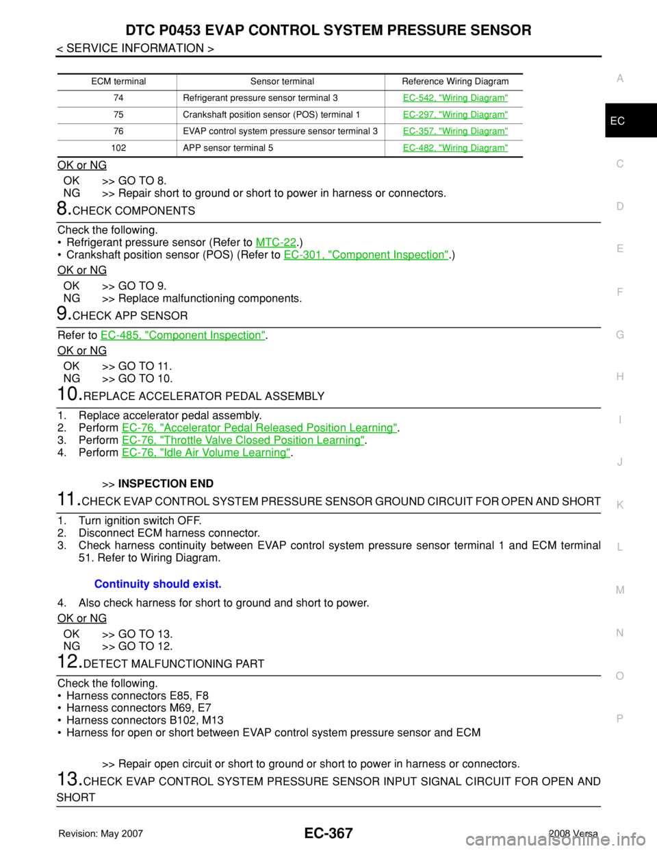
11 .CHECK EVAP CONTROL SYSTEM PRESSURE SENSOR GROUND CIRCUIT FOR OPEN AND SHORT
1. Turn ignition switch OFF.
2. Disconnect ECM harness connector.
3. Check harness continuity between EVAP control system pressure sensor terminal 1 and ECM terminal
51. Refer to Wiring Diagram.
4. Also check harness for short to ground and short to power.
OK or NG
OK >> GO TO 13.
NG >> GO TO 12.
12.DETECT MALFUNCTIONING PART
Check the following.
• Harness connectors E85, F8
• Harness connectors M69, E7
• Harness connectors B102, M13
• Harness for open or short between EVAP control system pressure sensor and ECM
>> Repair open circuit or short to ground or short to power in harness or connectors.
13.CHECK EVAP CONTROL SYSTEM PRESSURE SENSOR INPUT SIGNAL CIRCUIT FOR OPEN AND
SHORT
ECM terminal Sensor terminal Reference Wiring Diagram
74 Refrigerant pressure sensor terminal 3EC-542, "
Wiring Diagram"
75 Crankshaft position sensor (POS) terminal 1EC-297, "Wiring Diagram"
76 EVAP control system pressure sensor terminal 3EC-357, "Wiring Diagram"
102 APP sensor terminal 5EC-482, "Wiring Diagram"
Continuity should exist.
Page 1442 of 2771
EC-368
< SERVICE INFORMATION >
DTC P0453 EVAP CONTROL SYSTEM PRESSURE SENSOR
1. Check harness continuity between ECM terminal 42 and EVAP control system pressure sensor terminal
2. Refer to Wiring Diagram.
2. Also check harness for short to ground and short to power.
OK or NG
OK >> GO TO 15.
NG >> GO TO 14.
14.DETECT MALFUNCTIONING PART
Check the following.
• Harness connectors E8, F8
• Harness connectors M69, E7
• Harness connectors B102, M13
• Harness for open or short between ECM and EVAP control system pressure sensor
>> Repair open circuit or short to ground or short to power in harness or connectors.
15.CHECK RUBBER TUBE
1. Disconnect rubber tube connected to EVAP canister vent control valve.
2. Check the rubber tube for clogging, vent and kinked.
OK or NG
OK >> GO TO 16.
NG >> Clean the rubber tube using an air blower, repair or replace rubber tube.
16.CHECK EVAP CANISTER VENT CONTROL VALVE
Refer to EC-343, "
Component Inspection".
OK or NG
OK >> GO TO 17.
NG >> Replace EVAP canister vent control valve.
17.CHECK EVAP CONTROL SYSTEM PRESSURE SENSOR
Refer to EC-369, "
Component Inspection".
OK or NG
OK >> GO TO 18.
NG >> Replace EVAP control system pressure sensor.
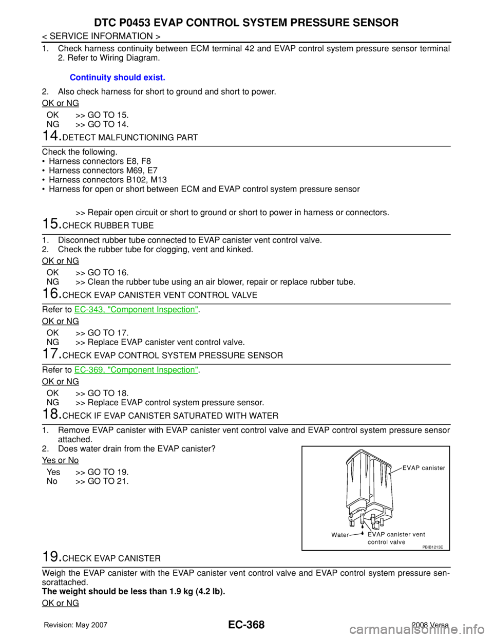
18.CHECK IF EVAP CANISTER SATURATED WITH WATER
1. Remove EVAP canister with EVAP canister vent control valve and EVAP control system pressure sensor
attached.
2. Does water drain from the EVAP canister?
Ye s o r N o
Yes >> GO TO 19.
No >> GO TO 21.
19.CHECK EVAP CANISTER
Weigh the EVAP canister with the EVAP canister vent control valve and EVAP control system pressure sen-
sorattached.
The weight should be less than 1.9 kg (4.2 lb).
OK or NG
Continuity should exist.
PBIB1213E