Page 1380 of 2771
EC-306
< SERVICE INFORMATION >
DTC P0340 CMP SENSOR (PHASE)
OK or NG
OK >> GO TO 3.
NG >> Repair or replace ground connections.
3.CHECK CAMSHAFT POSITION (CMP) SENSOR (PHASE) POWER SUPPLY CIRCUIT
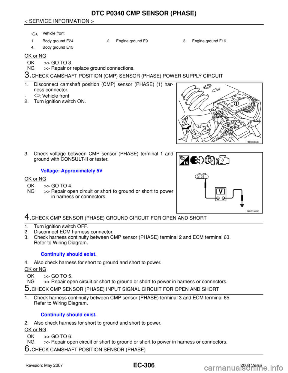
1. Disconnect camshaft position (CMP) sensor (PHASE) (1) har-
ness connector.
- : Vehicle front
2. Turn ignition switch ON.
3. Check voltage between CMP sensor (PHASE) terminal 1 and
ground with CONSULT-II or tester.
OK or NG
OK >> GO TO 4.
NG >> Repair open circuit or short to ground or short to power
in harness or connectors.
4.CHECK CMP SENSOR (PHASE) GROUND CIRCUIT FOR OPEN AND SHORT
1. Turn ignition switch OFF.
2. Disconnect ECM harness connector.
3. Check harness continuity between CMP sensor (PHASE) terminal 2 and ECM terminal 63.
Refer to Wiring Diagram.
4. Also check harness for short to ground and short to power.
OK or NG
OK >> GO TO 5.
NG >> Repair open circuit or short to ground or short to power in harness or connectors.
5.CHECK CMP SENSOR (PHASE) INPUT SIGNAL CIRCUIT FOR OPEN AND SHORT
1. Check harness continuity between CMP sensor (PHASE) terminal 3 and ECM terminal 65.
Refer to Wiring Diagram.
2. Also check harness for short to ground and short to power.
OK or NG
OK >> GO TO 6.
NG >> Repair open circuit or short to ground or short to power in harness or connectors.
6.CHECK CAMSHAFT POSITION SENSOR (PHASE)
:Vehicle front
1. Body ground E24 2. Engine ground F9 3. Engine ground F16
4. Body ground E15
PBIB3327E
Voltage: Approximately 5V
PBIB3312E
Continuity should exist.
Continuity should exist.
Page 1384 of 2771
EC-310
< SERVICE INFORMATION >
DTC P0420 THREE WAY CATALYST FUNCTION
Diagnosis Procedure
INFOID:0000000001702819
1.CHECK EXHAUST SYSTEM
Visually check exhaust tubes and muffler for dent.
OK or NG
OK >> GO TO 2.
NG >> Repair or replace.
2.CHECK EXHAUST GAS LEAK
1. Start engine and run it at idle.
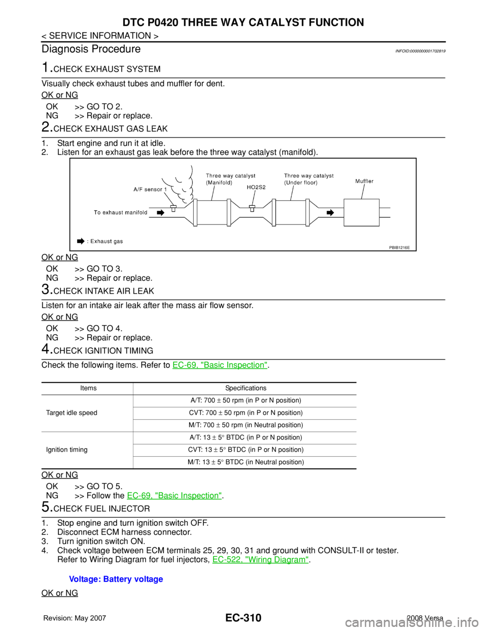
2. Listen for an exhaust gas leak before the three way catalyst (manifold).
OK or NG
OK >> GO TO 3.
NG >> Repair or replace.
3.CHECK INTAKE AIR LEAK
Listen for an intake air leak after the mass air flow sensor.
OK or NG
OK >> GO TO 4.
NG >> Repair or replace.
4.CHECK IGNITION TIMING
Check the following items. Refer to EC-69, "
Basic Inspection".
OK or NG
OK >> GO TO 5.
NG >> Follow the EC-69, "
Basic Inspection".
5.CHECK FUEL INJECTOR
1. Stop engine and turn ignition switch OFF.
2. Disconnect ECM harness connector.
3. Turn ignition switch ON.
4. Check voltage between ECM terminals 25, 29, 30, 31 and ground with CONSULT-II or tester.
Refer to Wiring Diagram for fuel injectors, EC-522, "
Wiring Diagram".
OK or NG
PBIB1216E
Items Specifications
Target idle speedA/T: 700 ± 50 rpm (in P or N position)
CVT: 700 ± 50 rpm (in P or N position)
M/T: 700 ± 50 rpm (in Neutral position)
Ignition timingA/T: 13 ± 5° BTDC (in P or N position)
CVT: 13 ± 5° BTDC (in P or N position)
M/T: 13 ± 5° BTDC (in Neutral position)
Voltage: Battery voltage
Page 1401 of 2771
DTC P0443 EVAP CANISTER PURGE VOLUME CONTROL SOLENOID VALVE
EC-327
< SERVICE INFORMATION >
C
D
E
F
G
H
I
J
K
L
MA
EC
N
P O
Wiring DiagramINFOID:0000000001702832
Specification data are reference values and are measured between each terminal and ground.
Pulse signal is measured by CONSULT-II.
CAUTION:
BBWA3000E
Page 1403 of 2771
DTC P0443 EVAP CANISTER PURGE VOLUME CONTROL SOLENOID VALVE
EC-329
< SERVICE INFORMATION >
C
D
E
F
G
H
I
J
K
L
MA
EC
N
P O
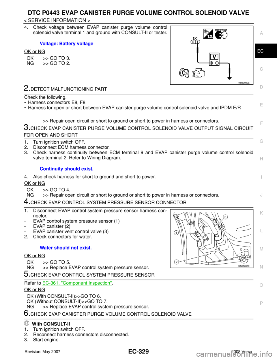
4. Check voltage between EVAP canister purge volume control
solenoid valve terminal 1 and ground with CONSULT-II or tester.
OK or NG
OK >> GO TO 3.
NG >> GO TO 2.
2.DETECT MALFUNCTIONING PART
Check the following.
• Harness connectors E8, F8
• Harness for open or short between EVAP canister purge volume control solenoid valve and IPDM E/R
>> Repair open circuit or short to ground or short to power in harness or connectors.
3.CHECK EVAP CANISTER PURGE VOLUME CONTROL SOLENOID VALVE OUTPUT SIGNAL CIRCUIT
FOR OPEN AND SHORT
1. Turn ignition switch OFF.
2. Disconnect ECM harness connector.
3. Check harness continuity between ECM terminal 9 and EVAP canister purge volume control solenoid
valve terminal 2. Refer to Wiring Diagram.
4. Also check harness for short to ground and short to power.
OK or NG
OK >> GO TO 4.
NG >> Repair open circuit or short to ground or short to power in harness or connectors.
4.CHECK EVAP CONTROL SYSTEM PRESSURE SENSOR CONNECTOR
1. Disconnect EVAP control system pressure sensor harness con-
nector.
- EVAP control system pressure sensor (1)
- EVAP canister (2)
- EVAP canister vent control valve (3)
2. Check connectors for water.
OK or NG
OK >> GO TO 5.
NG >> Replace EVAP control system pressure sensor.
5.CHECK EVAP CONTROL SYSTEM PRESSURE SENSOR
Refer to EC-361, "
Component Inspection".
OK or NG
OK (With CONSULT-II)>>GO TO 6.
OK (Without CONSULT-II)>>GO TO 7.
NG >> Replace EVAP control system pressure sensor.
6.CHECK EVAP CANISTER PURGE VOLUME CONTROL SOLENOID VALVE
With CONSULT-II
1. Turn ignition switch OFF.
2. Reconnect harness connectors disconnected.
3. Start engine.Voltage: Battery voltage
PBIB0080E
Continuity should exist.
Water should not exist.
BBIA0693E
Page 1408 of 2771
EC-334
< SERVICE INFORMATION >
DTC P0444, P0445 EVAP CANISTER PURGE VOLUME CONTROL SOLENOID
VALVE
Wiring Diagram
INFOID:0000000001702840
Specification data are reference values and are measured between each terminal and ground.
Pulse signal is measured by CONSULT-II.
CAUTION:
BBWA2640E
Page 1410 of 2771
EC-336
< SERVICE INFORMATION >
DTC P0444, P0445 EVAP CANISTER PURGE VOLUME CONTROL SOLENOID
VALVE
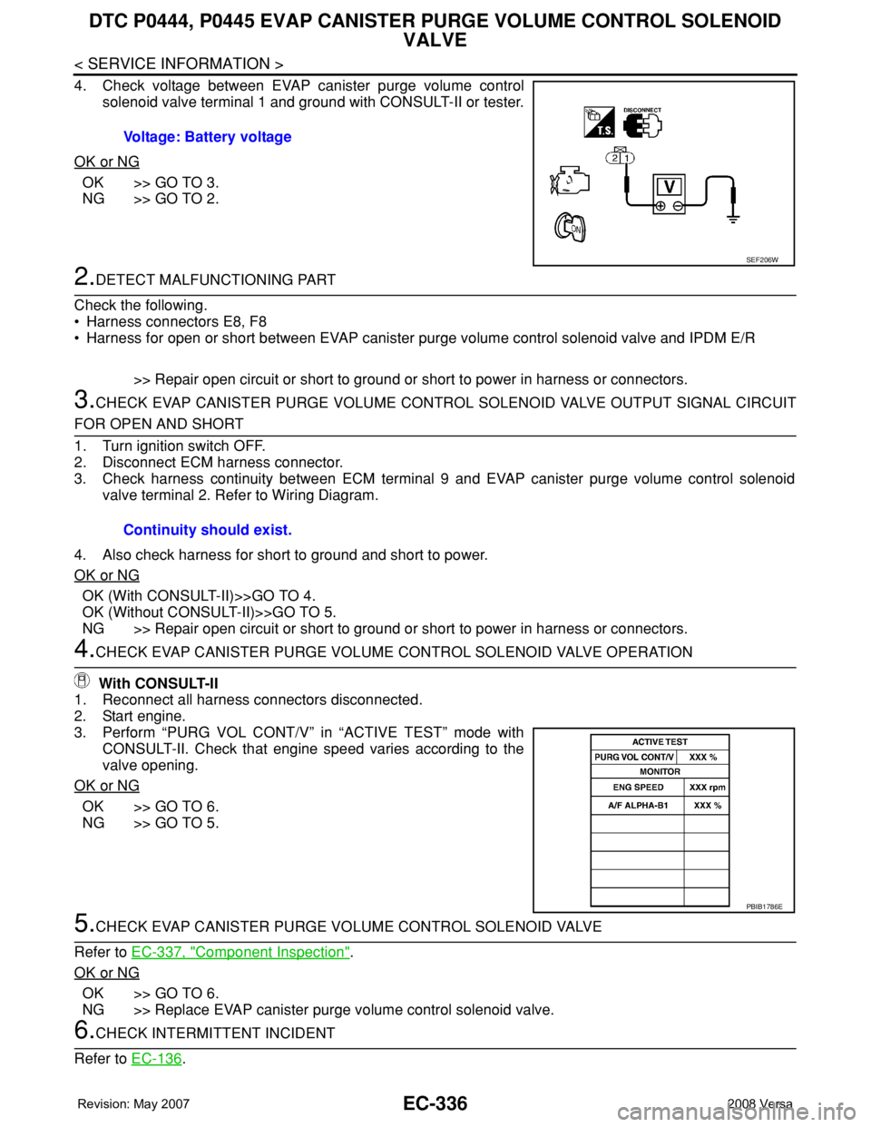
4. Check voltage between EVAP canister purge volume control
solenoid valve terminal 1 and ground with CONSULT-II or tester.
OK or NG
OK >> GO TO 3.
NG >> GO TO 2.
2.DETECT MALFUNCTIONING PART
Check the following.
• Harness connectors E8, F8
• Harness for open or short between EVAP canister purge volume control solenoid valve and IPDM E/R
>> Repair open circuit or short to ground or short to power in harness or connectors.
3.CHECK EVAP CANISTER PURGE VOLUME CONTROL SOLENOID VALVE OUTPUT SIGNAL CIRCUIT
FOR OPEN AND SHORT
1. Turn ignition switch OFF.
2. Disconnect ECM harness connector.
3. Check harness continuity between ECM terminal 9 and EVAP canister purge volume control solenoid
valve terminal 2. Refer to Wiring Diagram.
4. Also check harness for short to ground and short to power.
OK or NG
OK (With CONSULT-II)>>GO TO 4.
OK (Without CONSULT-II)>>GO TO 5.
NG >> Repair open circuit or short to ground or short to power in harness or connectors.
4.CHECK EVAP CANISTER PURGE VOLUME CONTROL SOLENOID VALVE OPERATION
With CONSULT-II
1. Reconnect all harness connectors disconnected.
2. Start engine.
3. Perform “PURG VOL CONT/V” in “ACTIVE TEST” mode with
CONSULT-II. Check that engine speed varies according to the
valve opening.
OK or NG
OK >> GO TO 6.
NG >> GO TO 5.
5.CHECK EVAP CANISTER PURGE VOLUME CONTROL SOLENOID VALVE
Refer to EC-337, "
Component Inspection".
OK or NG
OK >> GO TO 6.
NG >> Replace EVAP canister purge volume control solenoid valve.
6.CHECK INTERMITTENT INCIDENT
Refer to EC-136
. Voltage: Battery voltage
SEF206W
Continuity should exist.
PBIB1786E
Page 1414 of 2771
EC-340
< SERVICE INFORMATION >
DTC P0447 EVAP CANISTER VENT CONTROL VALVE
Wiring Diagram
INFOID:0000000001702848
Specification data are reference values and are measured between each terminal and ground.
CAUTION:
Do not use ECM ground terminals when measuring input/output voltage. Doing so may result in dam-
age to the ECM's transistor. Use a ground other than ECM terminals, such as the ground.
BBWA3072E
Page 1416 of 2771
EC-342
< SERVICE INFORMATION >
DTC P0447 EVAP CANISTER VENT CONTROL VALVE
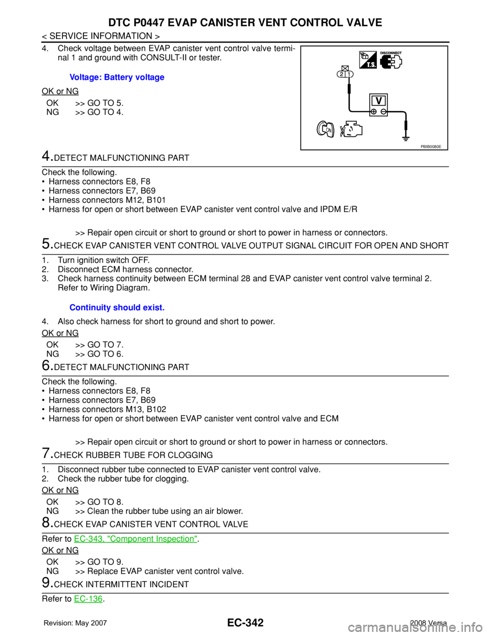
4. Check voltage between EVAP canister vent control valve termi-
nal 1 and ground with CONSULT-II or tester.
OK or NG
OK >> GO TO 5.
NG >> GO TO 4.
4.DETECT MALFUNCTIONING PART
Check the following.
• Harness connectors E8, F8
• Harness connectors E7, B69
• Harness connectors M12, B101
• Harness for open or short between EVAP canister vent control valve and IPDM E/R
>> Repair open circuit or short to ground or short to power in harness or connectors.
5.CHECK EVAP CANISTER VENT CONTROL VALVE OUTPUT SIGNAL CIRCUIT FOR OPEN AND SHORT
1. Turn ignition switch OFF.
2. Disconnect ECM harness connector.
3. Check harness continuity between ECM terminal 28 and EVAP canister vent control valve terminal 2.
Refer to Wiring Diagram.
4. Also check harness for short to ground and short to power.
OK or NG
OK >> GO TO 7.
NG >> GO TO 6.
6.DETECT MALFUNCTIONING PART
Check the following.
• Harness connectors E8, F8
• Harness connectors E7, B69
• Harness connectors M13, B102
• Harness for open or short between EVAP canister vent control valve and ECM
>> Repair open circuit or short to ground or short to power in harness or connectors.
7.CHECK RUBBER TUBE FOR CLOGGING
1. Disconnect rubber tube connected to EVAP canister vent control valve.
2. Check the rubber tube for clogging.
OK or NG
OK >> GO TO 8.
NG >> Clean the rubber tube using an air blower.
8.CHECK EVAP CANISTER VENT CONTROL VALVE
Refer to EC-343, "
Component Inspection".
OK or NG
OK >> GO TO 9.
NG >> Replace EVAP canister vent control valve.
9.CHECK INTERMITTENT INCIDENT
Refer to EC-136
. Voltage: Battery voltage
PBIB0080E
Continuity should exist.