2008 NISSAN TIIDA harness layout
[x] Cancel search: harness layoutPage 532 of 2771
BL-98
< SERVICE INFORMATION >
INTELLIGENT KEY SYSTEM
*1: With continuously variable transmission (CVT).
*2: With manual transmission (M/T).
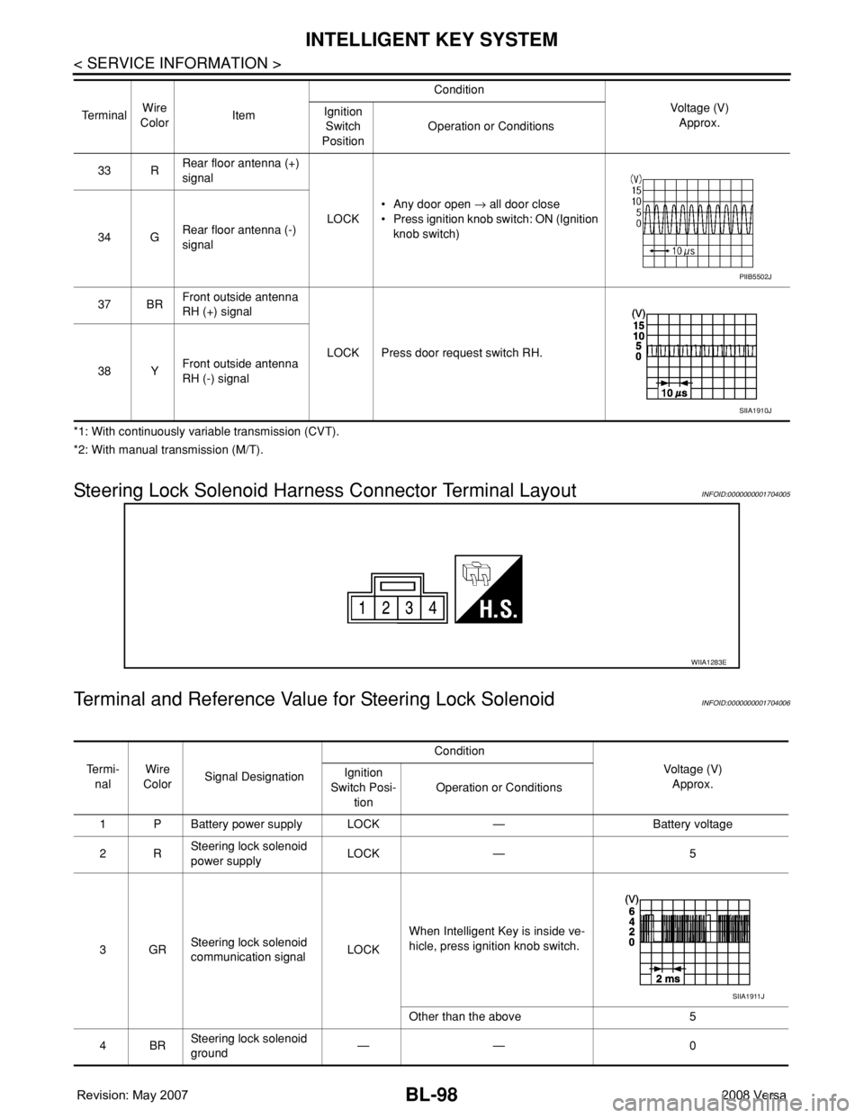
Steering Lock Solenoid Harness Connector Terminal LayoutINFOID:0000000001704005
Terminal and Reference Value for Steering Lock SolenoidINFOID:0000000001704006
33 RRear floor antenna (+)
signal
LOCK• Any door open → all door close
• Press ignition knob switch: ON (Ignition
knob switch)
34 GRear floor antenna (-)
signal
37 BRFront outside antenna
RH (+) signal
LOCK Press door request switch RH.
38 YFront outside antenna
RH (-) signal Te r m i n a lWire
ColorItemCondition
Voltage (V)
Approx. Ignition
Switch
PositionOperation or Conditions
PIIB5502J
SIIA1910J
WIIA1283E
Te r m i -
nalWire
ColorSignal DesignationCondition
Voltage (V)
Approx. Ignition
Switch Posi-
tionOperation or Conditions
1 P Battery power supply LOCK — Battery voltage
2RSteering lock solenoid
power supplyLOCK — 5
3GRSteering lock solenoid
communication signalLOCKWhen Intelligent Key is inside ve-
hicle, press ignition knob switch.
Other than the above 5
4BRSteering lock solenoid
ground—— 0
SIIA1911J
Page 884 of 2771
TROUBLE DIAGNOSIS
CVT-45
< SERVICE INFORMATION >
D
E
F
G
H
I
J
K
L
MA
B
CVT
N
O
P
9.CHECK ENGINE BRAKE FUNCTION — PART 3
1. Move selector lever to “L” position.
2. Check engine brake.
Does engine braking effectively reduce speed in
“L” position?
YES >> 1. Stop the vehicle.
2. Perform self-diagnosis. Refer to CVT-47, "
CONSULT-III Function (TRANSMISSION)" .
NO >> Mark the box of CVT-159, "
Vehicle Does Not Decelerate by Engine Brake" on the CVT-30, "How
to Perform Trouble Diagnosis for Quick and Accurate Repair" . Then continue trouble diagnosis.
Vehicle Speed When Shifting GearsINFOID:0000000001703461
Numerical value data are reference values.
CAUTION:
Lock-up clutch is engaged when vehicle speed is approximately 18 km/h (11 MPH) to 90 km/h (56 MPH).
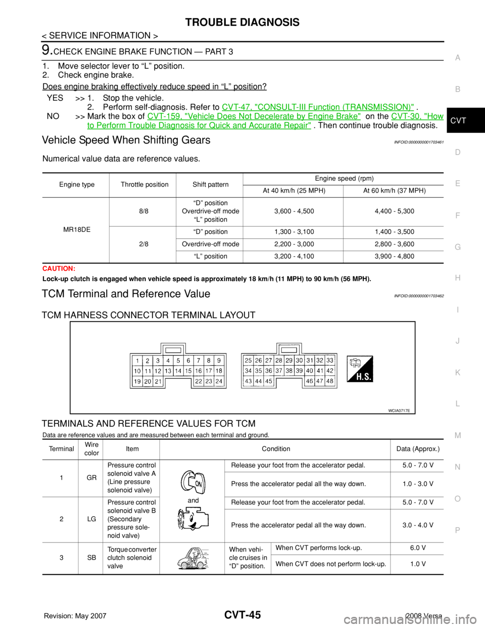
TCM Terminal and Reference ValueINFOID:0000000001703462
TCM HARNESS CONNECTOR TERMINAL LAYOUT
TERMINALS AND REFERENCE VALUES FOR TCM
Data are reference values and are measured between each terminal and ground.
Engine type Throttle position Shift patternEngine speed (rpm)
At 40 km/h (25 MPH) At 60 km/h (37 MPH)
MR18DE8/8“D” position
Overdrive-off mode
“L” position3,600 - 4,500 4,400 - 5,300
2/8“D” position 1,300 - 3,100 1,400 - 3,500
Overdrive-off mode 2,200 - 3,000 2,800 - 3,600
“L” position 3,200 - 4,100 3,900 - 4,800
WCIA0717E
Te r m i n a lWire
colorItem Condition Data (Approx.)
1GRPressure control
solenoid valve A
(Line pressure
solenoid valve)
and Release your foot from the accelerator pedal. 5.0 - 7.0 V
Press the accelerator pedal all the way down. 1.0 - 3.0 V
2LGPressure control
solenoid valve B
(Secondary
pressure sole-
noid valve) Release your foot from the accelerator pedal. 5.0 - 7.0 V
Press the accelerator pedal all the way down. 3.0 - 4.0 V
3SBTorque converter
clutch solenoid
valveWhen vehi-
cle cruises in
“D” position.When CVT performs lock-up. 6.0 V
When CVT does not perform lock-up. 1.0 V
Page 1022 of 2771

DI-1
ELECTRICAL
C
D
E
F
G
H
I
J
L
M
SECTION DI
A
B
DI
N
O
P
CONTENTS
DRIVER INFORMATION SYSTEM
SERVICE INFORMATION ............................2
PRECAUTION .....................................................2
Precaution for Supplemental Restraint System
(SRS) "AIR BAG" and "SEAT BELT PRE-TEN-
SIONER" ...................................................................
2
PREPARATION ...................................................3
Commercial Service Tool ..........................................3
COMBINATION METERS ...................................4
Component Parts and Harness Connector Loca-
tion ............................................................................
4
System Description ...................................................4
Arrangement of Combination Meter ..........................6
Internal Circuit ...........................................................7
Wiring Diagram - METER - .......................................8
Combination Meter Harness Connector Terminal
Layout .....................................................................
10
Terminal and Reference Value for Combination
Meter .......................................................................
10
Self-Diagnosis Mode of Combination Meter ............11
CONSULT-III Function (METER/M&A) ...................13
Trouble Diagnosis ...................................................14
Symptom Chart .......................................................15
Power Supply and Ground Circuit Inspection .........15
Vehicle Speed Signal Inspection .............................16
Engine Speed Signal Inspection .............................17
Fuel Level Sensor Signal Inspection .......................17
Fuel Gauge Fluctuates, Indicates Wrong Value, or
Varies ......................................................................
19
Fuel Gauge Does Not Move to Full-position ...........19
DTC [U1000] CAN Communication Circuit .............19
Electrical Component Inspection .............................19
Removal and Installation .........................................20
WARNING LAMPS .............................................21
Schematic ................................................................21
Wiring Diagram - WARN - .......................................22
Oil Pressure Warning Lamp Stays Off (Ignition
Switch ON) ..............................................................
30
Oil Pressure Warning Lamp Does Not Turn Off
(Oil Pressure Is Normal) ..........................................
32
Component Inspection .............................................32
A/T INDICATOR ................................................34
System Description ..................................................34
Wiring Diagram - AT/IND - .......................................35
A/T Indicator Does Not Illuminate ............................36
CVT INDICATOR ...............................................38
System Description ..................................................38
Wiring Diagram - CVTIND - .....................................38
CVT Indicator Does Not Illuminate ..........................39
WARNING CHIME .............................................41
Component Parts and Harness Connector Loca-
tion ...........................................................................
41
System Description ..................................................41
Wiring Diagram - CHIME - .......................................44
Terminal and Reference Value for BCM ..................45
CONSULT-III Function (BCM) .................................45
Trouble Diagnosis ....................................................46
Combination Meter Buzzer Circuit Inspection .........47
Front Door Switch LH Signal Inspection ..................48
Key Switch Signal Inspection (Without Intelligent
Key) .........................................................................
49
Key Switch and Ignition Knob Switch Signal In-
spection (With Intelligent Key, When Mechanical
Key Is Used) ............................................................
50
Lighting Switch Signal Inspection ............................52
Parking Brake Switch Signal Inspection ..................52
Electrical Component Inspection .............................53
Page 1031 of 2771
DI-10
< SERVICE INFORMATION >
COMBINATION METERS
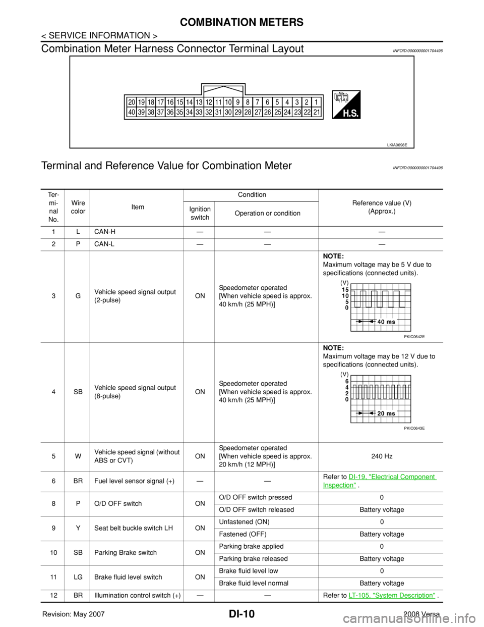
Combination Meter Harness Connector Terminal Layout
INFOID:0000000001704495
Terminal and Reference Value for Combination MeterINFOID:0000000001704496
LKIA0698E
Te r -
mi-
nal
No.Wire
colorItemCondition
Reference value (V)
(Approx.) Ignition
switchOperation or condition
1LCAN-H — — —
2PCAN-L — — —
3GVehicle speed signal output
(2-pulse)ONSpeedometer operated
[When vehicle speed is approx.
40 km/h (25 MPH)] NOTE:
Maximum voltage may be 5 V due to
specifications (connected units).
4SBVehicle speed signal output
(8-pulse)ONSpeedometer operated
[When vehicle speed is approx.
40 km/h (25 MPH)]NOTE:
Maximum voltage may be 12 V due to
specifications (connected units).
5WVehicle speed signal (without
ABS or CVT)ONSpeedometer operated
[When vehicle speed is approx.
20 km/h (12 MPH)]240 Hz
6 BR Fuel level sensor signal (+) — —Refer to DI-19, "
Electrical Component
Inspection" .
8 P O/D OFF switch ONO/D OFF switch pressed 0
O/D OFF switch released Battery voltage
9 Y Seat belt buckle switch LH ONUnfastened (ON) 0
Fastened (OFF) Battery voltage
10 SB Parking Brake switch ONParking brake applied 0
Parking brake released Battery voltage
11 LG Brake fluid level switch ONBrake fluid level low 0
Brake fluid level normal Battery voltage
12 BR Illumination control switch (+) — — Refer to LT- 1 0 5 , "
System Description" .
PKIC0642E
PKIC0643E
Page 1075 of 2771

EC-1
ENGINE
C
D
E
F
G
H
I
J
K
L
M
SECTION EC
A
EC
N
O
P
CONTENTS
ENGINE CONTROL SYSTEM
SERVICE INFORMATION ............................9
INDEX FOR DTC .................................................9
DTC No. Index ..........................................................9
Alphabetical Index ...................................................12
PRECAUTIONS ..................................................16
Precaution for Supplemental Restraint System
(SRS) "AIR BAG" and "SEAT BELT PRE-TEN-
SIONER" .................................................................
16
Precaution for Procedure without Cowl Top Cover ....16
On Board Diagnosis (OBD) System of Engine and
A/T, CVT .................................................................
16
Precaution ...............................................................17
PREPARATION ..................................................20
Special Service Tool ...............................................20
Commercial Service Tool ........................................21
ENGINE CONTROL SYSTEM ............................22
Schematic ...............................................................22
Multiport Fuel Injection (MFI) System .....................22
Electronic Ignition (EI) System ................................25
Fuel Cut Control (at No Load and High Engine
Speed) .....................................................................
25
AIR CONDITIONING CUT CONTROL ...............27
Input/Output Signal Chart ........................................27
System Description .................................................27
AUTOMATIC SPEED CONTROL DEVICE
(ASCD) ...............................................................
28
System Description .................................................28
Component Description ...........................................29
CAN COMMUNICATION ....................................30
System Description .................................................30
EVAPORATIVE EMISSION SYSTEM ................31
Description ..............................................................31
Component Inspection ............................................33
Removal and Installation .........................................35
How to Detect Fuel Vapor Leakage .........................35
ON BOARD REFUELING VAPOR RECOV-
ERY (ORVR) ......................................................
38
System Description ..................................................38
Diagnosis Procedure ...............................................38
Component Inspection .............................................40
POSITIVE CRANKCASE VENTILATION .........43
Description ...............................................................43
Component Inspection .............................................43
NVIS (NISSAN VEHICLE IMMOBILIZER SYS-
TEM-NATS) .......................................................
45
Description ...............................................................45
ON BOARD DIAGNOSTIC (OBD) SYSTEM ....46
Introduction ..............................................................46
Two Trip Detection Logic .........................................46
Emission-related Diagnostic Information .................47
Malfunction Indicator Lamp (MIL) ............................60
OBD System Operation Chart .................................63
BASIC SERVICE PROCEDURE .......................69
Basic Inspection ......................................................69
Idle Speed and Ignition Timing Check .....................73
Procedure After Replacing ECM .............................75
VIN Registration ......................................................75
Accelerator Pedal Released Position Learning .......76
Throttle Valve Closed Position Learning .................76
Idle Air Volume Learning .........................................76
Fuel Pressure Check ...............................................78
TROUBLE DIAGNOSIS ....................................81
Trouble Diagnosis Introduction ................................81
DTC Inspection Priority Chart ..................................86
Fail-Safe Chart ........................................................87
Symptom Matrix Chart .............................................88
Engine Control Component Parts Location .............93
Vacuum Hose Drawing ............................................99
Circuit Diagram ......................................................100
ECM Harness Connector Terminal Layout ............102
Page 1176 of 2771
EC-102
< SERVICE INFORMATION >
TROUBLE DIAGNOSIS
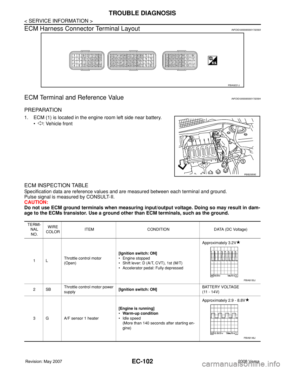
ECM Harness Connector Terminal Layout
INFOID:0000000001702593
ECM Terminal and Reference ValueINFOID:0000000001702594
PREPARATION
1. ECM (1) is located in the engine room left side near battery.
• : Vehicle front
ECM INSPECTION TABLE
Specification data are reference values and are measured between each terminal and ground.
Pulse signal is measured by CONSULT-II.
CAUTION:
Do not use ECM ground terminals when measuring input/output voltage. Doing so may result in dam-
age to the ECMs transistor. Use a ground other than ECM terminals, such as the ground.
PBIA9221J
PBIB2959E
TERMI-
NAL
NO.WIRE
COLORITEM CONDITION DATA (DC Voltage)
1LThrottle control motor
(Open)[Ignition switch: ON]
• Engine stopped
• Shift lever: D (A/T, CVT), 1st (M/T)
• Accelerator pedal: Fully depressedApproximately 3.2V
2SBThrottle control motor power
supply[Ignition switch: ON]BATTERY VOLTAGE
(11 - 14V)
3 G A/F sensor 1 heater[Engine is running]
•Warm-up condition
• Idle speed
(More than 140 seconds after starting en-
gine)Approximately 2.9 - 8.8V
PBIA8150J
PBIA8148J
Page 1861 of 2771
GI-10
< SERVICE INFORMATION >
HOW TO USE THIS MANUAL
3.Refer to Component Parts and Harness Connector Location for the Systems described in each
section for identification/location of components and harness connectors.
4.Refer to the Circuit Diagram for quick pinpoint check.
If you need to check circuit continuity between harness connectors in more detail, such as when a
sub-harness is used, refer to Wiring Diagram in each individual section and Harness Layout in PG
section for identification of harness connectors.
5.When checking circuit continuity, ignition switch should be OFF.
6.Before checking voltage at connectors, check battery voltage.
7.After accomplishing the Diagnostic Procedures and Electrical Components Inspection, make sure
that all harness connectors are reconnected as they were.
HOW TO FOLLOW TEST GROUPS IN TROUBLE DIAGNOSES
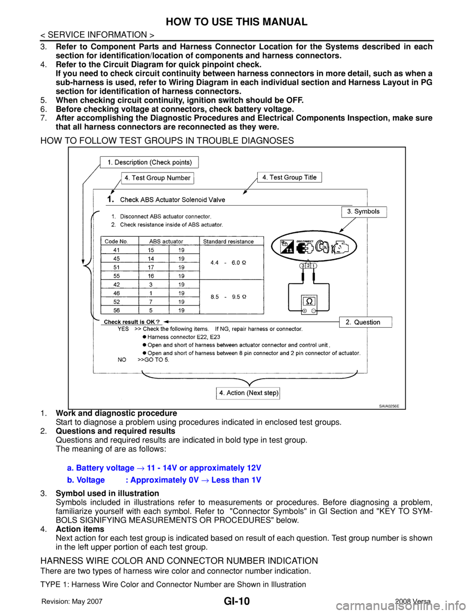
1.Work and diagnostic procedure
Start to diagnose a problem using procedures indicated in enclosed test groups.
2.Questions and required results
Questions and required results are indicated in bold type in test group.
The meaning of are as follows:
3.Symbol used in illustration
Symbols included in illustrations refer to measurements or procedures. Before diagnosing a problem,
familiarize yourself with each symbol. Refer to "Connector Symbols" in GI Section and "KEY TO SYM-
BOLS SIGNIFYING MEASUREMENTS OR PROCEDURES" below.
4.Action items
Next action for each test group is indicated based on result of each question. Test group number is shown
in the left upper portion of each test group.
HARNESS WIRE COLOR AND CONNECTOR NUMBER INDICATION
There are two types of harness wire color and connector number indication.
TYPE 1: Harness Wire Color and Connector Number are Shown in Illustration
SAIA0256E
a. Battery voltage → 11 - 14V or approximately 12V
b. Voltage : Approximately 0V → Less than 1V
Page 1868 of 2771
HOW TO USE THIS MANUAL
GI-17
< SERVICE INFORMATION >
C
D
E
F
G
H
I
J
K
L
MB
GI
N
O
P
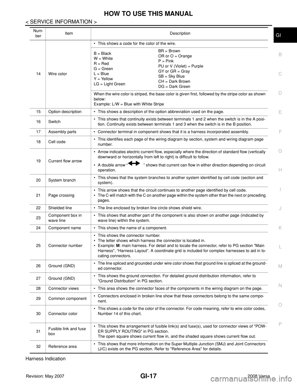
Harness Indication
14 Wire color• This shows a code for the color of the wire.
B = Black
W = White
R = Red
G = Green
L = Blue
Y = Yellow
LG = Light GreenBR = Brown
OR or O = Orange
P = Pink
PU or V (Violet) = Purple
GY or GR = Gray
SB = Sky Blue
CH = Dark Brown
DG = Dark Green
When the wire color is striped, the base color is given first, followed by the stripe color as shown
below:
Example: L/W = Blue with White Stripe
15 Option description • This shows a description of the option abbreviation used on the page.
16 Switch• This shows that continuity exists between terminals 1 and 2 when the switch is in the A posi-
tion. Continuity exists between terminals 1 and 3 when the switch is in the B position.
17 Assembly parts • Connector terminal in component shows that it is a harness incorporated assembly.
18 Cell code• This identifies each page of the wiring diagram by section, system and wiring diagram page
number.
19 Current flow arrow• Arrow indicates electric current flow, especially where the direction of standard flow (vertically
downward or horizontally from left to right) is difficult to follow.
• A double arrow “ ” shows that current can flow in either direction depending on circuit
operation.
20 System branch• This shows that the system branches to another system identified by cell code (section and
system).
21 Page crossing• This arrow shows that the circuit continues to another page identified by cell code.
• The C will match with the C on another page within the system other than the next or preceding
pages.
22 Shielded line • The line enclosed by broken line circle shows shield wire.
23Component box in
wave line• This shows that another part of the component is also shown on another page (indicated by
wave line) within the system.
24 Component name • This shows the name of a component.
25 Connector number• This shows the connector number.
• The letter shows which harness the connector is located in.
•Example: M: main harness. For detail and to locate the connector, refer to PG section "Main
Harness", “Harness Layout”. A coordinate grid is included for complex harnesses to aid in lo-
cating connectors.
26 Ground (GND)• The line spliced and grounded under wire color shows that ground line is spliced at the ground-
ed connector.
27 Ground (GND)• This shows the ground connection. For detailed ground distribution information, refer to
"Ground Distribution" in PG section.
28 Connector views • This area shows the connector faces of the components in the wiring diagram on the page.
29 Common component• Connectors enclosed in broken line show that these connectors belong to the same compo-
nent.
30 Connector color• This shows a code for the color of the connector. For code meaning, refer to wire color codes,
Number 14 of this chart.
31Fusible link and fuse
box• This shows the arrangement of fusible link(s) and fuse(s), used for connector views of "POW-
ER SUPPLY ROUTING" in PG section.
The open square shows current flow in, and the shaded square shows current flow out.
32 Reference area• This shows that more information on the Super Multiple Junction (SMJ) and Joint Connectors
(J/C) exists on the PG section. Refer to "Reference Area" for details. Num-
berItem Description